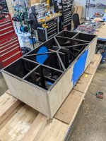
For a new topcabinet, I needed a MF/HF (or only HF) section, which is able to handle a crossover around 700Hz. The whole design revolves around maximum output for a given size. The dual 10" LF section is loaded by a short offset driver horn and ported rear chamber. For this to work, I knew from the beginning, that a relative low crossover was necessary (approximately 700-800Hz as an estimate). In total the following demands are set:
-Low XO possibility (700-800Hz)
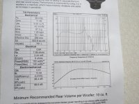
-Maximum hight and width 29x29cm total
-+- 80 degrees horizontal dispersion
-50/60 degrees vertical dispersion
-Rotatable horn for possible horizontal arraying
This all could be solved by going for a coaxial CD or large 4" VC and for example a RCF HF950 horn. But there is no fun in that.
So I wanted to try a different (and unknown for me) path for this project. After some minor research I decided to just start with some design work and see what can or will come out.
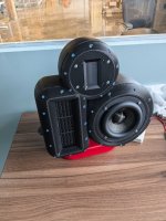
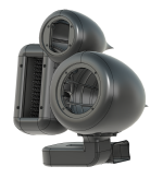
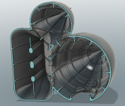
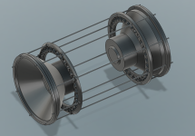
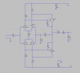
This gave the following:
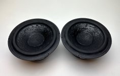
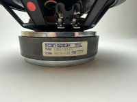
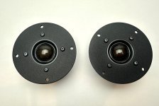
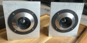
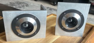
The MF drivers are two 4ND34-16 from B&C, and a new RCF NDX595.
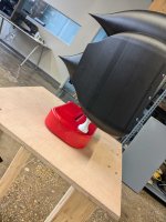
The whole horn is for now printed out of 5 parts total due to the size of my current printer. In the end its the idea to bring it down to two and outsource the frontal part.
As I wanted to be flexible with some testing, I made the MF taps removable. This way i can test various placements, sizes and shapes.
By doing so, I am a bit limted in vertical placement eventually though, but priting that whole parts again takes a lot of time and money if I have to do that several times.
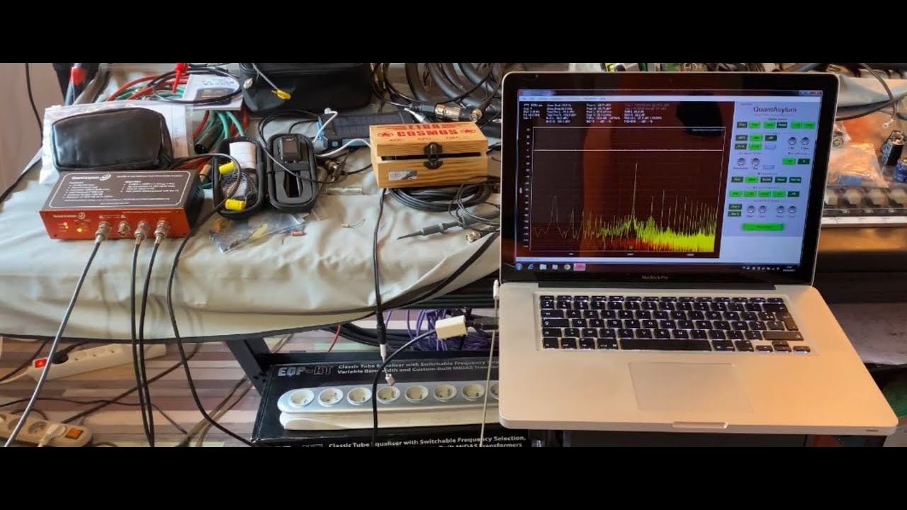
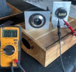
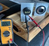
As I wanted to try it ASAP, I made some preliminary inside measurements with a calibrated UMIK-1. Its not ideaal, but gives a first impression.
Distance mic to SUT +- 40cm.
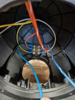
2x4NDF34-16 parallel, taps a close as possible with insert, two 22mm round holes (total area 7,6cm^2 per 4NDF34) + NDX595:
With this measurement, the back of both 4NDF34's was open.
I tried my best by closing the back of the 4NDF34's with gaffa tape and got the following results:
I will be printing some better parts for the drivers to get it better and neatly, I am quite sure its leaking currently.
The 1kHz dip of the NDX595 is due to the current tap design an placement. When covering with some pieces of tape:
To try and reduce the dip at 1kHz, I did a quick test with a MF tap inserts which has several small holes compared to the two 22mm diamter ones per driver.
Response evened out quite a bit, but less high end extension from the 4NDF34's:
Currently next things I want to do:
-New insert with angled taps (facing away from CD)
-Resolve some resonating parts I still have
-Make a turning table for some off-axis measurements
-Back covers for 4NDF34
-Measure NDX595 on the PH220 I have for some sort of reference
-Get my other measurement mic calibrated again to get some measurements with phase response. This will be crucial to eventually get a nice crossover and if going passive MF tap placement is key from the beginning.
-Do some impedance measurements
-Get a whole day to do various measurements and outside or larger room.
-In the end the HF exit integration can be smoothed out/be better
Its still a work in progress and the outcome could still be that its not viable in the end or does not meet the set criteria. But we will see
🙂