For a new topcabinet, I needed a MF/HF (or only HF) section, which is able to handle a crossover around 700Hz. The whole design revolves around maximum output for a given size. The dual 10" LF section is loaded by a short offset driver horn and ported rear chamber. For this to work, I knew from the beginning, that a relative low crossover was necessary (approximately 700-800Hz as an estimate). In total the following demands are set:
-Low XO possibility (700-800Hz)
-Maximum hight and width 29x29cm total
-+- 80 degrees horizontal dispersion
-50/60 degrees vertical dispersion
-Rotatable horn for possible horizontal arraying
This all could be solved by going for a coaxial CD or large 4" VC and for example a RCF HF950 horn. But there is no fun in that.
So I wanted to try a different (and unknown for me) path for this project. After some minor research I decided to just start with some design work and see what can or will come out.
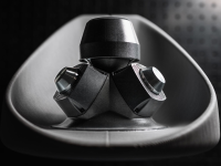
This gave the following:


The MF drivers are two 4ND34-16 from B&C, and a new RCF NDX595.
The whole horn is for now printed out of 5 parts total due to the size of my current printer. In the end its the idea to bring it down to two and outsource the frontal part.
As I wanted to be flexible with some testing, I made the MF taps removable. This way i can test various placements, sizes and shapes.
By doing so, I am a bit limted in vertical placement eventually though, but priting that whole parts again takes a lot of time and money if I have to do that several times.
As I wanted to try it ASAP, I made some preliminary inside measurements with a calibrated UMIK-1. Its not ideaal, but gives a first impression.
Distance mic to SUT +- 40cm.
2x4NDF34-16 parallel, taps a close as possible with insert, two 22mm round holes (total area 7,6cm^2 per 4NDF34) + NDX595:

With this measurement, the back of both 4NDF34's was open.
I tried my best by closing the back of the 4NDF34's with gaffa tape and got the following results:

I will be printing some better parts for the drivers to get it better and neatly, I am quite sure its leaking currently.
The 1kHz dip of the NDX595 is due to the current tap design an placement. When covering with some pieces of tape:

To try and reduce the dip at 1kHz, I did a quick test with a MF tap inserts which has several small holes compared to the two 22mm diamter ones per driver.

Response evened out quite a bit, but less high end extension from the 4NDF34's:

Currently next things I want to do:
-New insert with angled taps (facing away from CD)
-Resolve some resonating parts I still have
-Make a turning table for some off-axis measurements
-Back covers for 4NDF34
-Measure NDX595 on the PH220 I have for some sort of reference
-Get my other measurement mic calibrated again to get some measurements with phase response. This will be crucial to eventually get a nice crossover and if going passive MF tap placement is key from the beginning.
-Do some impedance measurements
-Get a whole day to do various measurements and outside or larger room.
-In the end the HF exit integration can be smoothed out/be better
Its still a work in progress and the outcome could still be that its not viable in the end or does not meet the set criteria. But we will see 🙂
-Low XO possibility (700-800Hz)
-Maximum hight and width 29x29cm total
-+- 80 degrees horizontal dispersion
-50/60 degrees vertical dispersion
-Rotatable horn for possible horizontal arraying
This all could be solved by going for a coaxial CD or large 4" VC and for example a RCF HF950 horn. But there is no fun in that.
So I wanted to try a different (and unknown for me) path for this project. After some minor research I decided to just start with some design work and see what can or will come out.
This gave the following:
The MF drivers are two 4ND34-16 from B&C, and a new RCF NDX595.
The whole horn is for now printed out of 5 parts total due to the size of my current printer. In the end its the idea to bring it down to two and outsource the frontal part.
As I wanted to be flexible with some testing, I made the MF taps removable. This way i can test various placements, sizes and shapes.
By doing so, I am a bit limted in vertical placement eventually though, but priting that whole parts again takes a lot of time and money if I have to do that several times.
As I wanted to try it ASAP, I made some preliminary inside measurements with a calibrated UMIK-1. Its not ideaal, but gives a first impression.
Distance mic to SUT +- 40cm.
2x4NDF34-16 parallel, taps a close as possible with insert, two 22mm round holes (total area 7,6cm^2 per 4NDF34) + NDX595:
With this measurement, the back of both 4NDF34's was open.
I tried my best by closing the back of the 4NDF34's with gaffa tape and got the following results:
I will be printing some better parts for the drivers to get it better and neatly, I am quite sure its leaking currently.
The 1kHz dip of the NDX595 is due to the current tap design an placement. When covering with some pieces of tape:
To try and reduce the dip at 1kHz, I did a quick test with a MF tap inserts which has several small holes compared to the two 22mm diamter ones per driver.
Response evened out quite a bit, but less high end extension from the 4NDF34's:
Currently next things I want to do:
-New insert with angled taps (facing away from CD)
-Resolve some resonating parts I still have
-Make a turning table for some off-axis measurements
-Back covers for 4NDF34
-Measure NDX595 on the PH220 I have for some sort of reference
-Get my other measurement mic calibrated again to get some measurements with phase response. This will be crucial to eventually get a nice crossover and if going passive MF tap placement is key from the beginning.
-Do some impedance measurements
-Get a whole day to do various measurements and outside or larger room.
-In the end the HF exit integration can be smoothed out/be better
Its still a work in progress and the outcome could still be that its not viable in the end or does not meet the set criteria. But we will see 🙂

Picking up this project in a couple of weeks, still need to do some printing.
Cool, which 10” did you choose?
I’m also working on back covers for 4ndf34 at the moment! How are you planning to seal them? I thought about using O rings sealing against the surface just above the mounting holes..
I’m also working on back covers for 4ndf34 at the moment! How are you planning to seal them? I thought about using O rings sealing against the surface just above the mounting holes..
For the sealing, i was thinking of a two part shell which sits under the magnet and fixed by the mounting screws. Will post a sketch when i have a more definitive one. Getting it fully close will need some silicone or gasket.
10" i am opting for the PD 103.NR1.
10" i am opting for the PD 103.NR1.
- Home
- Loudspeakers
- Multi-Way
- Small 3D printed unity horn