Help with noise in tube amp EL34A

Hello
I need some help with a Chinese tube amp that I’m using for one of my turntable setups
It’s a el34A type amp
When nothing is playing, I hear soMe noise in my speakers, it does not sound like a 60hz buzz, or I don’t think it is. I just tried some other tubes in it and still has the same noise
I have meters and a scope, not very handy with my scope, have it for setups input gain for car amps.
What steps and how do I accomplish these steps to track down the source of this noise.
Also one other problem I’m having is that the left speaker channel is not as loud as the right channel. And it’s the same no matter if I’m playing the turntable or cd inputs.
Here’s a photo of the amp, later today I’ll flip it over and remove the bottom plate and take photos of the inside
Thanks for any and all help
P.S. I’m a newbie with doing this type of stuff so please try to dump it down for me lol
IMG_7824.jpg
IMG_7825.jpg
IMG_7826.jpg
IMG_8048.jpg

comparing the sound of amplifiers -- a fair test

I start this thread because I want to make sure I'm giving my First Watt J2 a fair chance to compete with a few other amps. Cause so far, it's not sounding good to me...

This has nothing to do with measurements -- only a listening evaluation where I keep the source and the speakers constant. The variable is power amps.
Speakers: Tannoy V12
Source: iphone 5s
All amplifiers have been warmed up for 2 hours. The switch from amp-to-amp takes about 30 sec, thanks to phenix connectors.

Let's say I have 5 amplifiers and I want to figure out which ones sound best to my ears.

Is it fair to evaluate good amplifiers from an iphone 5s, as the source of music material?

synchonized streaming to multiple clients/loudspeakers

I wanted to start a thread on this topic. I'm curious if people know of software that can keep two or more streams very tightly synchronized. I do not mean "multiroom streaming" - that just needs to be approximately synchronized, e.g. below 1 second difference. I am talking about 1 millisecond (!) or less difference between the playback on two or more clients.

Why have such a strict requirement for synchronicity? For example, it is to send audio separately to playback systems in the left speaker and the right speaker. In order for the stereo image to stay in the middle and not wander from side to side, the time difference must stay well below 1 msec.

Another reason I am asking is that I just made some changes to the Gstreamer based app I wrote and that I use to stream audio around my home. I now seem to be able to stream to multiple clients and keep the stereo image centered. This means that I will be able to build two completely self-contained, independent active speakers and deploy them as a left+right pair anywhere in my home, with just an AC mains connection/plug and no other external wiring.

If there is enough interest in this from others I will be happy to share my app with everyone. It's a much improved version of my GSASysCon app that I first described a few years ago. It can stream and implement DSP on the clients. Add multichannel DACs at the clients and you have a streaming, DSP crossover audio system that can be reconfigured at will. In the past, it has been the documentation that has prevented me from releasing versions as I make improvements because it is very tedious and complicated to explain everything in sufficient detail. It would be great if I could get some "testers" signed up to do some test runs and give me feedback on everything.

NOTE: when I say "app" I do not mean something that you install on your phone. This is a Linux based bash script with a Gstreamer backend doing all the heavy lifting. You must be able to have multiple Linux computers (R-Pi 3 or 4 or similar, minimum) and DACs to implement this system. Experience setting up and maintaining headless systems and using SSH is useful.

KiCad combined diode layout

Hi everyone,

I am trying and failing to make a layout for a diode that can take both vertical TO-220 and horizontal like 1n4007 diodes. I've seen people do it on boards, but can't find an existing layout or come up with an easy way to do that. It is basically keeping one square pad and make a duplicate further away for the second round pad on the layout. Any suggestions?

Can I make RH84 from these parts ?

Can I make RH84 Amplifier from these parts ?

Hello people
I have few parts as follows.

1) ECC83/12AT7 and EL84 valves
2) One Big transformer as giving supply (350-0-350v)(6.3v)(6V)
3) Two Big Chokes of size around 2.5 inch W x 2.5 inch D x 4 Inch H. Friend who gave it to me says One with Original value of 15H is giving 4H and another 14H one with 10H.
4) Two Small chokes of size around 2 inch x 1 inch (H Value unknown)
5) Two Output transformer with 4 terminal (Probably taps for various impedance) on one side and 3 terminals on other (So probably for pushpull OT) 5K and 7K is written on it with marker pen

My questions are

1) Can I use 350-0-350v PT for RH84's EL84 Valve ? recommended voltage is 315V
2) Original RH84 Schematic shows 10H100mA Choke in PS. Can I use two in series that I already have (4H+10H) so as to give more filtering ?
2) As suggested by Audiowize in another thread. Using small chokes between rectifier and Capacitors will reduce some voltage. Correct ?
3) Can I use (pushpull OT) that I have just to check the output and sound testing purpose ? will buy single ended OT later if all OK.

tell me how to go about this with parts I have.
thanks and regards

Disadvantages replace SSM2212/10 with with two NPN Transistors

Hello together I'm new in this forum and i hope you could help me.
I'm in a project to make my own amplifier. My question is: What are the disadvantages for replace a SSM2212 or SSM2210 Transistor with two normal NPN transistors like 2N5401? I can't find a good replacement for the SSM22112/10 and I don't want to buy one for like 50 $.
Sorry for my english I'm from Germany hope you understand 😉
Thank you in advance!

A newbie guide into cheap Class D boards

I decided to start this after I bought a cheap tda7492 board that sounds not so good, and the info on modding it and component selection was scattered all around, so I picked it up and compiled the usefull knowledge here.


Please, read all before doing anything to your board, and specially go trough step 4 before changing components at the output.


All that info apply to Class D without feedback, please refer to the datasheet of your module and make sure you dont change anything out of specs. The most relevant references are here:


Trevor's blog little class D tuto

Texas Instruments notes

Texas's output filter calculator
EETimes article
Maxim Itegrated aaplication note on types of caps for audio

Your module/chip datasheet (this one is your job, go find it)


First, there may be 4 probable fonts of unwanted hum, hiss or noise in your board
1 bad quality components
2 bad signal input
3 bad ground connections
4 bad output filter


1 Lets start by the most common, the nightmare of audiophiles, bad quality capacitors!
These little guys can mess with everything you want, on the maxim note they explain that. TL/DR chinese use cheap X7R ceramic caps, cheap and small, but they act like a piezo element, when voltage is applied they deform, change capacitance, and resonate with the circuit, you don't want nothing resonating, you just want you audio signal.
If you see small light brown smd caps they're probably X7R, if they are on audio paths, it'd be good to change for some multilayer polymer dieletric (polyester, mylar, polycarbonate, polyestirene) or to NP0 caps, since they dont give a **** about voltage, temperature or current variation, and they have reasonably low esr. DON'T use electrolitic caps here, they have HIGH esr, so they are most suited for storing energy than signal conitioning.


2 Second, if you have bad audio input, you'll have bad audio output, amps don't do magic. Make sure you have a matching input, if your amp is single ended, use single ended signal, and so on.
Make sure you have good coupling caps at your input. Coupling caps are in series with the input conector and the chip input, if they are X7R, make sure to change them, the datasheet of the board or the chip can suggest good values to use.
If you have a buffer(little amp with no gain, in level=out level, used to match impedance) make sure that it's a good one by reading the chip datasheet, if you're not sure, ask for help at the forum on if its ok to leave and if not how to mod it.

When you can, use differential input, it will sound better since it dont have ground connection, gnd usually carry heavy noise caused by the fast switching output.


3 Here we are, this one is a bit complicated, please do some research on "ground plane pcb desing" and "star connected ground".

Since everything that's referenced to ground have to be connected to it, including the output supply, they will probably share the same noise, and output stage on Class D cause a hell of a noise, so watch your connections carefully, this can be mitigated by some clever path designing, but I'm not the most suited to teach ou this.


4 The baddest of all, poorly designed output filter.

The output filter work by getting rid of the switching carrier frequency, so you get only the audio that was superimposed at the modulation stage. A filter is an association of capacitors and inductors/coils, and think what also have a coil inside? Yes, your speaker. So an output filter need to be designed to match the speaker you will use. It can be done with some room for change, like design it for 5 ohms, so it work with both 4 ohms and 6 ohms.
But, chinese manufacturers usually use what they want, and usually they want you to use 8 ohms or higher.


Output filters have a quality factor, that tells you how good it is filtering. For a given filter, you'll have a linear response till the cut frequency, that for class D is usually 22-40 KHz, and then a sudden step down in response. If you change the speaker, you change a bit of the filter inductance, so you change your filter caracteristics. Usually, by increasing speaker impedance you increase qualitiy factor, good right?
High quality factor will give you a stepper response at the cut out frequency, but will give a huge spike right below it, so if your filter has a high Q, and cut frequency at 22KHz, you will see harsh threbble cause of the huge spike near cut out frequency.
Lower Q will give you a smooth roll off, that happen by reducing speaker's impedance, so youl get poor performance at high frequencies.
Texas Instrument has given us an excel sheet that do all the heavy calculation, just look at you board and insert the values here, then see what happens, and play with them a bit.
Here's mine stock components calculations:
attachment.php
Interesting to note: Even if these boards should perform poorly with treble at lower impedances, the effects of X7R caps give it a nasty harsh sound.


After some tweaking for my 4ohm speaker:
attachment.php


Besides all that, they tend to use the cheapest coils and caps they have. The caps where already adressed, but the inductors play a key role here.
The inductor have a max current at wich they still work as an inductor, after it the losses increase at an incredible rate. So if you want to dry out every single watt of your amp, take in consideration the DC current that can pass trough the coil, so use a coil that can endure that. A rule of thumb is that more current = denser magnetic field, and core material have a limited capacity of magnetic fiel for a given core area(pls dont correct me on these terms, they're for sake of understanding, not for technical specs), so if you want a bigger current, use a coil with bigger core area, and the same value of inductance.

Core material should be ferrite/ceramic, since we're talking abou high frequency, 250-400Khz.


After you've checked all that above, you can look at your board and try to extract the schematic of the amp, principally the filter, and compare it to the seggested topology of the datasheet, if you see some diversion, it'd be good to correct it, like, some boards lack a snubber, a device that supresses transients and prevent your amp from being a radio antenna, it is a resistor in series with a little cap, conected between the amp outputs, before the filter.


I, like most of you, dont have a setup for complex measurements here, but if you've done it right, now you should have a good sound board, some people, like Trevor, even use those on HiFi setups.

Attachments

  • Graph.jpg
    Graph.jpg
    126.8 KB · Views: 640
  • graph 2.jpg
    graph 2.jpg
    127.6 KB · Views: 520

Looking for old Soundstream amplifiers to fix up and use

Hey guys, Moderators please remove if this is not allowed!

I'm looking for some old 2 and large 4-channel Soundsteam amplifiers to use/rebuild and add to my system. Working or not is OK as long as the price is alright. I could not find a for sale section on this site so not sure if buying/selling is even allowed?

If you have one of these or similar, please send me a picture with your username on a piece of paper on the amp, price etc. Inside photo would be nice too to.

MC500
MC300
Reference 500/700/1000
Class A 10

Or similar, but needs to be MADE IN THE USA - so no Korean amps please (Like the REF800.4 - no thank you).

Not looking for any smaller rated 4 nor 5 channel amps at this time.

Thank you for your time

Plate Resistor?

I am building a pre-amp that I want to allow changing between two different B+ voltages with the change of the 2 VR tubes. I need to also change the 4 plate resistors from 47K to 33K and I'd like to do that without opening the chassis. Can I switch in a parallel resistor, as illustrated, without loss of fidelity?
I believe my calculation is correct but I'll double check before building.
T9CklbU.jpg
[/IMG]

SMW60N06-18 sub for Orion NT200

Hello , new user here, I'm looking for a sub for said number in title. One shorted so I need to replace the 8 on one side and suppose I should duplicate the other channel as well so they are from the same production run. I appreciate any feedback ahead of time, this amp is just a personal project for myself and I'm sure I'll be back again with more questions and photos.

Dibya’s TDA7293 Xmas amp by Jhofland - Giveaway

This thread is to organize the logistics of the subject amplifier PCB giveaway. Technical details of the amp can be found here:

Xmas Amp - Dibya's TDA7293 by Jhofland

For technical discussions please use the other thread (above link).

904728d1608921278-xmas-amp-dibyas-tda7293-jhofland-tda7293-rev2-render-top-png


Schematics here:

https://www.diyaudio.com/forums/att...7293-jhofland-tda7293_-schematic_12_06_20-pdf

Photo of actual PCB:
911428d1610572719-dibya-tda7293-xmas-amp-jhofland-giveaway-15a22920-6784-4a09-b441-f931b070ca85-jpeg


The amp has been fully tested and verified by Vunce and myself. We have a few minor edits for Jhofland to include in the final layout. The full amp schematics, BOM, and Gerber files are freely available for anyone to make their own boards. But this thread is for those who signed up in the other thread to get a free board for the cost of shipping.

Vunce’s verification build:
908876d1609945042-xmas-amp-dibyas-tda7293-jhofland-274ff2be-939b-4c89-8cbf-a5aa0a4ef367-jpeg


My verification build:
911191d1610526506-xmas-amp-dibyas-tda7293-jhofland-tda7293-nbuild-07-jpg


Closeup of the assembled boards:
910860d1610437340-xmas-amp-dibyas-tda7293-jhofland-tda7293-nbuild-01-jpg


910861d1610437340-xmas-amp-dibyas-tda7293-jhofland-tda7293-nbuild-02-jpg


Edit Jan 18, 2021: Latest measurements show that this amp has excellent performance with low THD and a natural non-fatiguing harmonic distortion proifile. Here is a loud playing 6.4Wrms into 10ohms:
attachment.php


Very loud 40Wrms into 10ohms:
attachment.php


It’s a great sounding amp! Easy to build and works very well. I recommend either 200VA to 250VA 25v trafo (either dual secondaries or center tap) or dual mono 100VA to 200VA 25v trafos. Nominal voltage is +/-35v and as high as +/-37v for design as presented with LM317/337L regulators. For 50v rails, use the zener diode mod in the other thread and big heatsink. The +/-15v voltages are needed for the DC servo.

To keep things simple, folks who are on the current list will send the shipping funds via PayPal and please include your DIYA screen name and your shipping address name and address in the PayPal payment. To keep things simple I will use a fixed shipping costs as follows.

Amounts are in USD and covers cost of PayPal fees, bubble padded mailer envelopes, and shipping labels. Cost for shipping will be $5 in USA, $8 in Canada, and $15 everywhere else. Boards will be sent via USPS First Class mail. No tracking and no insurance to keep costs low. As I have mentioned, you can also download the Gerbers linked in other thread and have your own boards made for not much money if you don’t want to participate in the giveaway.

I will compare your DIYA screen name in the PayPal payment to the list below to track the number of people. I am giving away 25 sets of two boards, they will be 1.6mm thick with 2oz copper and green solder mask.

Please send your PayPal funds to my address at xrk971 “at” rfasystems “dot” com.

Don’t forget to include your screen name and address.

Thanks, and happy belated Xmas and New Year!

A big thanks to Dibya for the inspiration and original design features and thanks to Jhofland for the final design and layout. Big thanks to Vunce for verifying the build.

Here is the current giveaway list:
MaxReboBand / 2 boards / USA
as8912 / 2 boards / USA
ahtllc / 2 boards / USA
Flamethrower1 /2 boards/ USA
Signal Lost / 2 boards / USA
diy.tiger / 2 boards / NZ
MShipmanPE/ 2 boards / USA
Angchuck / 2 boards / Singapore
Francois G / 2 boards / USA
Asuslover /2 boards /USA
astromo / 2 boards / Australia
Kay Pirinha / 2 boards / Germany
Sixto / 2 boards / USA
Tubesguy / 2 boards / USA
Hicoco / 2 boards / France
Kokanee / 2 boards / Canada
chermann/ 2 boards / Austria
twocents/ 2 boards / USA
s610adam / 2 boards / USA
hochopeper/ 2 boards / Australia
Jlevro / 2 boards / USA
nautibuoy / 2 boards / UK
invaderzim / 2 boards / USA
kp93300/ 2 boards/ Malaysia
comicrcc / 2 boards / USA

Waiting List:

Legis31/ 2 boards/ usa
Pandpliers/ 2 boards/ USA
DarpMalone / 2 Boards / Canada

Attachments

  • 15A22920-6784-4A09-B441-F931B070CA85.jpeg
    15A22920-6784-4A09-B441-F931B070CA85.jpeg
    527.7 KB · Views: 1,122

DCX2496 passive out

Hi
I am busy modding a DCX2496, put in passive output, wanted to change PSU, dropped the +15 and -15 Volt, because only needed for audio opamps, I thought...
When I started it up, lights come on, display is dead, checked schematics, OK there is a 072 opamp on DSP board, also needs +15/-15 volt power, that will be for the LCD display, does anyone know if the DCX will work without the +15/-15 volt power, I think only when adjusting settings display is needed, or am I wrong?
Cheers, Tom.

Sony CDP-707ESD with CD not spinning. Need help!

I have been reading this audio forum for a couple of years and I am really impressed with the knowledge and support the members are providing. I got a used Sony CPD-707ESD about 7 years ago and up to today it used to work fine. This is a really nice sounding CD and have been enjoying its performance in my system. Today I loaded the cd on the cd tray and it closed without any issues. Then the display was showing DISC & MEMO and it did not play the CD. I tried several times by opening/closing the cd tray and it did not play. I opened the top cover and observed that the cd tray was functioning properly by closing the tray and lowering the chucking arm. Then the CD did not start spinning. I checked the motor connector and could not see anything wrong with it. Please let me know how to go about troubleshooting this issue, your help is really appreciated.

AT2380v2 2Ch Digitally controlled Stepped Attenuator

Frex The 26/11/2017

AT2380v2 Dual Channel Digitally controlled stepped attenuator Group-Buy

The dedicated thread of the project on DIYaudio is here :

AT2380v1 // 2 Channels digitally controlled stepped attenuator


Project description :
----------------------------


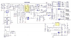
The AT2380 is a dual channels digitally controlled passive stepped attenuator.
It can be used to reduce the signal level in order to fit with the range of the target device.

It has been designed to doesn’t introduce any significant distortion and noise by using fully
passive attenuation network with high performance resistors.
There is NO active parts in the signal path.
To avoid any noise contamination from all on-board digital control circuitry,
all clocks can be disable keeping the attenuator to it’s current state (frizzed value).

One of the main purpose of this attenuator is to help performing signals measurements
(when testing audio devices for example) with analysis hardware such an audio sound-card.
Anyway, it can be of course used for any purpose where signal level control is needed.

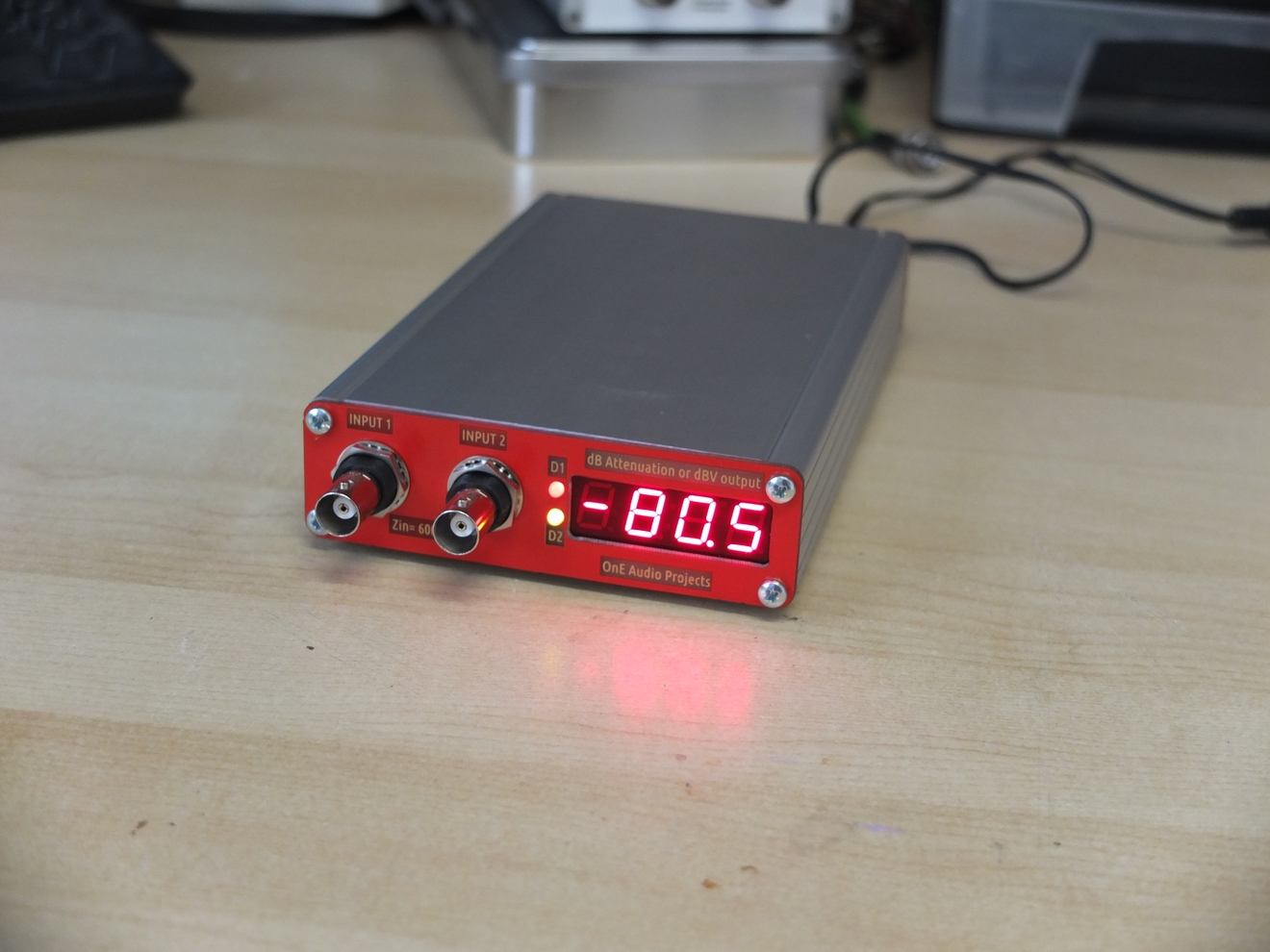
For ease of use, the attenuation setting is made by a single rotary encoder
and it’s value is displayed directly on a four digits seven-segment LEDs display.
In addition, if some optional parts are mounted, an auto-track mode is available.
The auto track mode allow user to select directly in dBV the desired
output voltage level wanted at the output of the attenuator. (servo control loop).

The entire design fit in an small aluminium enclosure and the PCB panel include the main
board and also front and rear panel already drilled and engraved.
So, there is no need to make any drilling to get a very clean and beautiful DIY instruments !


The key specs are :
----------------------------

  • full digital control (5M570 CPLD, VHDL coded).
  • 2 pseudo isolated attenuators Channels
  • Zin= 600 Ohms , Zout = ~ 0 to 300 Ohms (Can be modified if needed)
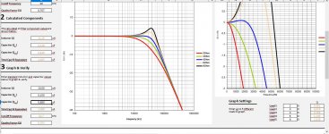
  • Flat frequency response (± 0,05dB) from DC..1MHz
  • 0 to 127,5 dB attenuation in 0,5 dB step (8 bits / 256 steps)
  • Direct dB attenuation setting displayed on 4 digits seven segments LEDs.
  • Five selectable dB steps : 0.5 ,1 , 3, 6 and 10 dB by encoder increment.
  • Optional output level auto-tracking mode from +10 dBV to – 85 dBV (attenuation only) .
  • Full internal clock enable switch, for ultra quiet operation mode (no spurious).
  • Shielded design to improve RF performance and noise immunity .
  • Low cost design and easy to find parts.
  • 100x160mm PCB size, fit in Hammond 1455 series extruded aluminium enclosure.
  • Front and rear panels are made in PCB with all holes drilled and with gold silkscreen.
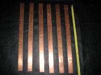
  • Through holes axial or SMD (1206) ladder attenuator resistors types.

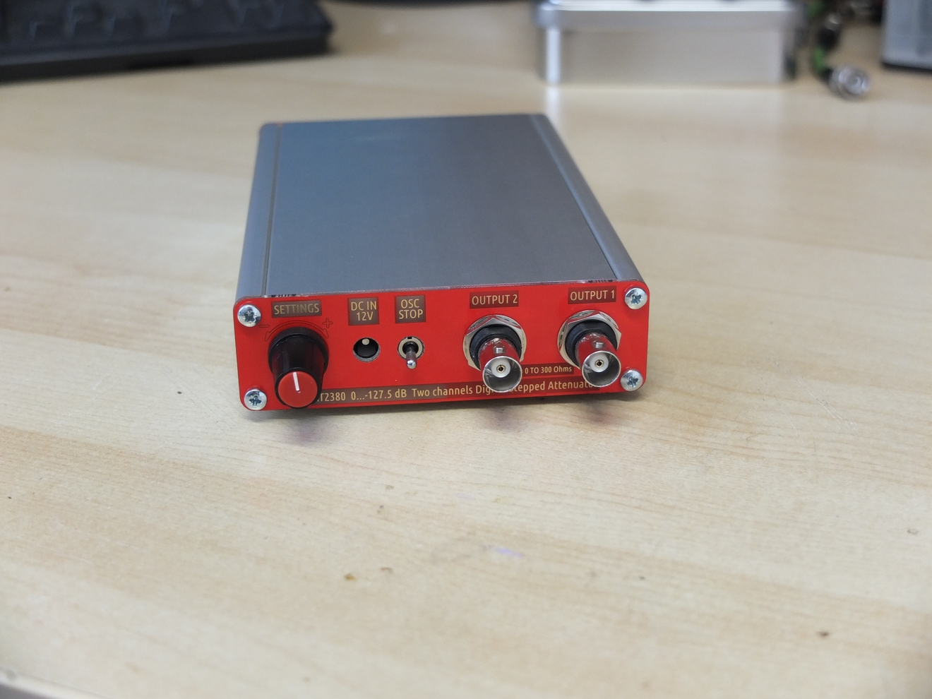
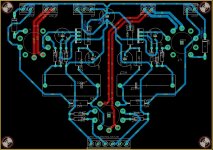
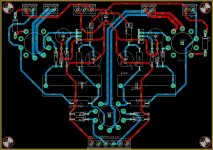
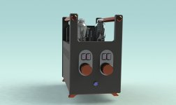
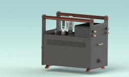
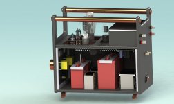
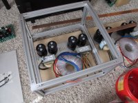
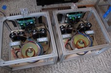
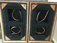
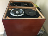
Below, some pictures of the unit (the v1 prototype !) :

AT2380_done_09.jpg


AT2380_done_01.jpg


You can also show the attenator in situation in these two presentation videos :

AT2380 DIY 2 channels digitally controlled stepped attenuator- Introduction video Part 1/2

AT2380 DIY 2 channels digitally controlled stepped attenuator- Introduction video Part 2/2


Some documents are available below for download (30/11/2017 update) :
--------------------------------------------------------------------------


Group-buy organization :
------------------------------------


I open now a group buy for the 
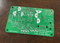
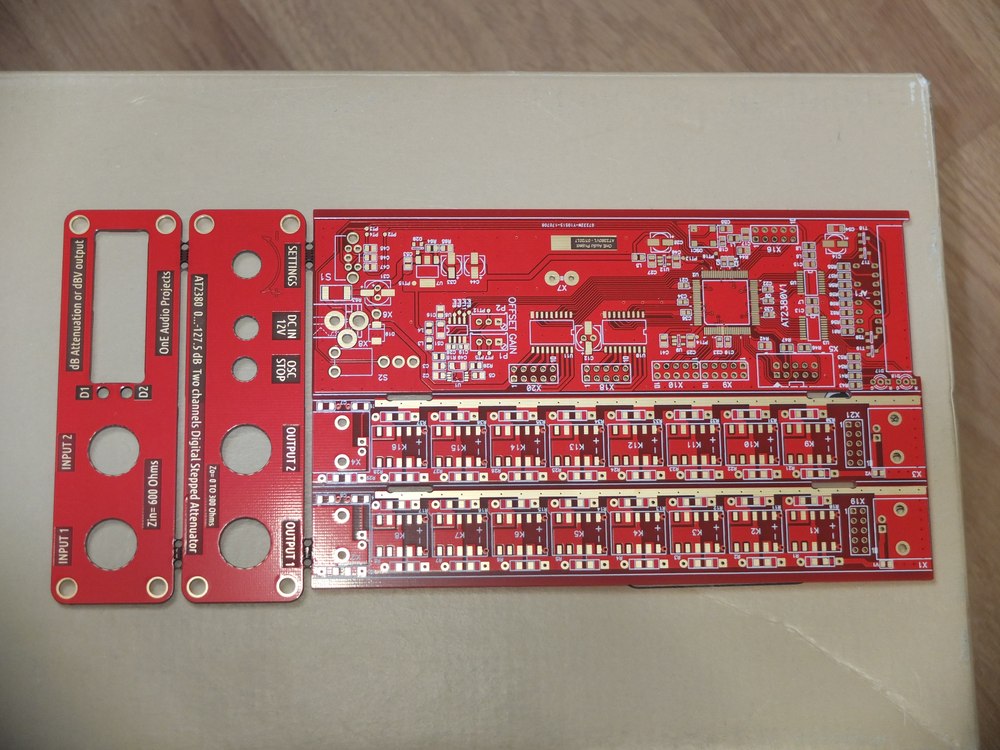
BARE PCB of the AT2380v2 project.
It's a PCB panel including the 2 layers 100x160 main PCB and
the front and rear panels for the 1455 Hammond enclosure.
Panels are drilled with all holes and marking, they are also
part of shielding.

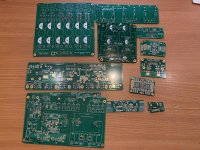
Bare PCB(v1) picture:
AT2380v1_barepcb.JPG


The minimum number of order required is 10.
If this quantity is reached, the price would be 30€ all included.
(Bare PCB, worldwide shipping in priority letter without insurance, and Paypal fees).
The price could be lowered if pre-order quantity is much higher(>20).

I provide two bom files, with and without tracking mode enabled.
These bom file can be imported directly in Mouser for fast and convenient
parts ordering.
All parts list are coming from Mouser, so ordering is easy and fast.


The total Mouser bom cost are (this day):
---------------------------------------------------------

AT2380v2 without track mode : 114€
AT2380v2 with track mode : 135€

This include all parts, enclosure and button.
(You just need to find a small translucent red Plexiglas for the 7 segments display).
(The bom cost doesn't include the PCB)


It is a pre-order list, i will ask for payment as soon minimum order is reached
If there is no sufficient pre-order, i will cancel the group-buy.
The group-buy is opened until 16 December 2017.
At this time, i will ask for payment to order PCB to manufacturer (PCBcart).


I provide to all PCB buyers a very complete design folder,
including many documents and the full CPLD code source (writed in VHDL).
(it can be tweaked if needed).
IMPORTANT NOTE : You need an USB-Blaster to load the CPLD firmware in the CPLD.
(You can find it for few €/$ on ebay or Aliexpress)


If you are interested to join the group-buy :

Send me a PM with your location (country) and the number of PCB required
or post a message and then i will edit the buyers list below :


Pre-order list for the AT2380v2 bare PCB's:
-----------------------------------------------------------


Pseudo--Qty-----Location (country) ---- Payment received -------------Letter sent ------------ Receipt acknowledge
Frex--------------------------1--------France-----------------Payment DONE
Jcga--------------------------1--------France-----------------Payment DONE---------------------------Shipped----------------Confirmed
jhenderson01075 -------1--------USA--------------------Payment DONE-----------------------------Shipped
CeeVee---------------------1--------Portugal---------------Payment DONE----------------------------Shipped----------------Confirmed
Duster1---------------------2--------Estonia-----------------Payment DONE---------------------------Shipped
hallodeletue---------------2--------Germany--------------Payment DONE----------------------------Shipped----------------Confirmed
_jan_ -----------------------2--------Germany---------------Payment DONE---------------------------Shipped
markus22ch --------------2--------Switzerland-----------Payment DONE----------------------------Shipped
diyaudnut------------------1-------USA----------------------Payment DONE---------------------------Shipped-------------------Confirmed
bk856er--------------------1--------USA---------------------Payment DONE---------------------------Shipped-------------------Confirmed
mkc--------------------------1--------Danemark-------------Payment DONE--------------------------Shipped
Emynet---------------------1------- Italy----------------------Payment DONE--------------------------Shipped
Demian---------------------2-------USA---------------------Payment DONE---------------------------Shipped
gazzagazza---------------1-------New Zealand---------Payment DONE----------------------------Shipped-------------------Confirmed
mlloyd1 --------------------2-------USA-----------------------Payment DONE-------------------------Shipped-------------------Confirmed
Techland-------------------2------ Germany-----------------Payment DONE--------------------------Shipped
BDL--------------------------1-------Romania----------------Payment DONE--------------------------Shipped-------------------Confirmed
Zigi---------------------------2-------Poland-------------------Payment DONE--------------------------Shipped

------------------------------------------------------
TOTAL Pre-order = 26

Good news, on 30/11, the minimum order is reached !

NOTE : because of a more bigger per-orders than expected,
the panel price goes down and will be 25€ instead of 30€.
(including shipping and Paypal fees).


The 16/12/2017 -- GROUP BUY IS NOW CLOSED.

All Paypal invoices has been been sent.
PCB manufacturing will be send as soon all payment done.
Payment status can be show on the above table.


UPDATE The 22/12/2017
All payments has been received, thanks to all.
The PCB order has been sent for manufacturing and will arrive in about 10 days.
I will post pictures as soon they are in my hands.
All letters will be send to all in stride.

Update the 30/12/2017
The four design files linked above has been updateded
according to first reales of design folder.


Update the 04/01/2018
Bare PCB are arrived this day.
Letters will be prepared for shipping
in next days.


Update the 08/01/2018
All letters has been shipped.
Please, inform me when it's in your hands 🙂

Frex


I hope that enjoy some DIYers 🙂

Frex

Loudspeaker for acoustically horrible space

I'm looking to build a pair of nice small unobtrusive floorstanders for our conservatory/garden room (acoustic abomination of a long thin space with a stone floor and walls and ceiling that are mostly glass). So acoustically treating the surfaces is pretty well a none starter, as the main purpose is to see out of them. So I was thinking some kind of baby MTM/D'Appolito design to try and reduce the reflections from the hard floor (I may be able to get a rug down there) and ceiling that slopes across the listening space. They will be placed near the side walls about 2/5 way down the length of the space, the room is barely 2m wide and 4.25m long. The space is a thoroughfare to the garden so these have to tuck to the sides and be discrete otherwise a hooning child will send one flying on their way our of the door.

Ideally I was looking at something Totem Arro like, but then though a bit taller and MTM might benefit the space acoustically. I have some Fountek Neo CD3.0 tweets which never really did what I wanted in a previous build, I think trying to cross them at 2.sometihing khz was asking a bit much. This has lead to ideas of pairing the Founteks with something like a pair of ScanSpeak 12w discovery drivers or the Seas CA12RCY as an MTM in a tall slim cabinet. Would i do as well with the 4.5" drivers as a simple long thin 2 way? I'm hoping the smaller cone should allow me to cross higher and get the best out of the Fountek.

Any thought on this or other suggestions?

Thanks

FS: Jordan Jx92s drivers.

Renowned jordan jx92s drivers.

Lovely condition drivers, used up until only last week, where I made the hard decision to sell these as have too many speakers. They were house in a Jon Espley concrete t line cabinet.

They come in thier original packaging.

Happy to ship if buyer arranges post, I can print labels etc.

Please feel free to make an offer. I know these were about £200 ish each new I believe some years back, so offering them at £150 for the pair, ex post.

I am looking for some ribbon tweeters, so happy to do a swap.

Please pm if interested.
Will try get some pics up in a bit, happy to email plenty over in the meantime.

Upload photos

I've previously been able to upload photos with no issues but when I tried last night, and again this afternoon, I'm having no luck. I get as far as the "Manage Attachments" pop-up window but when I click on the "Choose File" button nothing happens. I would expect to see a file select window open to allow me to select the files to upload, but nothing appears. I tried rebooting my computer but alas no joy.

I'm using Safari browser on a MacBook, but also tried Chrome in case it was a browser related issue.

Better living room acoustic systems surpassed by headphones

All acoustic systems, commercial or DIY, will never sound like a good pair of headphones. It is an incontestable and undeniable fact.
My room system is not the best, but it is not to devalue either, I have spent a lot of time and money on it, but I do not get with it the sound of my old AKG K-141, which I still use, and it is supposed to be outperformed by current models ...
The Sennheissers were also superb, I remember the first ones (which were really ugly, but they used mylar diaphragms and that did the miracle.

Sennheiser HD 414 and 424 – Old School | TONEAudio MAGAZINE

The subsequent intensive use of this material wiped out the heavy eyes with transistor radio mini-speakers inside!
This was the Pionner SE 305, they were a Chinese torture, bad sound, heavy and suffocating.
Even a pair of mid-priced, recent manufacture Phillips headphones have bass with surprising resolution, my "room" system doesn't have "the one-note bass", but it's different, there's no transparency or harmonics that gives a good headphone in the low end of the spectrum.
My favorites were always the open system, (the air is not locked in the ear tunnel, breathe)
For example, I had Koss, I remember the HV-1A and the HVX, I had both. What transparency and definition they had!
So, if you want the best sound in the world for little money, you know ......

Attachments

  • 122-400x258@2x.jpg
    122-400x258@2x.jpg
    69.2 KB · Views: 295
  • HVX-1.jpg
    HVX-1.jpg
    64.9 KB · Views: 268
  • f10c17584550283f63b67c5fb2fcc89c.jpg
    f10c17584550283f63b67c5fb2fcc89c.jpg
    29.4 KB · Views: 262
  • K141_studio.jpg
    K141_studio.jpg
    26.2 KB · Views: 262

Steel enclosures and Bluetooth/Radio reception

Hi Guys,


I am integrating a bluetooth reciever board and an FM radio board into an amplifier I am building.


If the bluetooth board was installed inside a mild steel enclosure, would the shielding effect of the mild steel compromise with bluetooth reception?


The same question applies regarding an FM radio receiver board inside the same enclosure. Would the reception be compromised if installed inside a mild steel enclosure?

2 Behringer DCX-2496 and 1 DEQ-2496 FS

I have the listed equipment in good cosmetic and functional condition for sale. Make me an offer I can't refuse (I do know what they're worth). Will not separate they go as siblings. I have cables to throw in for free if the buyer is interested. Items located in Ontario Canada so any shipping would be at the expense of the buyer. Payment options are bank e-Transfer or cash in hand, not making exceptions. I'll get them out of the boxes and take a pic or two later. Final sale, no tradebacks or refunds 😉 .

DM me with offers. Low ballers will obviously not get a reply.

Audiophile quality subwoofer?

How demanding should an audiophile be about the quality of the amplifier for the subwoofer?

I ask because it seems difficult to imagine what we can hear. For full range speakers, distortion and transient response are obviously important. Because the speakers are full range, they presumably participate in the full transient response. Also, any harmonic distortion is within range of the speakers' reproduction.

With a subwoofer, though, harmonics might be rolled off. I'm also a little fuzzy about what "transients" might be after they've gone through a low-pass filter. Sure, if the subwoofer waveform were synthesized from raw waveforms without a low-pass, then transients could be incredibly sharp. i.e. a dedicated LFE channel is not necessarily band-limited. But a low-pass filter on a full-range sound source will smooth out transients significantly, and I wonder how the subwoofer can have a sharp transient response after things have been rolled off.

In my setup, I have a passive subwoofer cabinet, fed by a full range amplifier, which is fed by a DAC. The low-pass filtering is done on a mono mix of the stereo input, through a Linkwitz-Riley crossover (low output only - my full range speakers are still full range, not high-pass), and the final signal is dithered before the 24-bit DAC to hopefully remove truncation noise. The catch here is that any harmonic distortion in the power amplifier will be passed to the subwoofer driver without any low-pass filtering.

Besides the questions above, I'm also wondering whether the ideal subwoofer might still have some passive low-pass filtering components in between the amplifier output and driver. Unfortunately, this would make varying the cutoff difficult compared to the pure DSP setup I have now. But a possible advantage would be to minimize harmonic distortion, whatever there may be.

I guess the core of my question is: What do we perceive when listening to a subwoofer, and what would the audiophile concerns be to focus on improving?

p.s. I'm ignoring the size of the cabinet, resonant frequency, ported versus non-ported, isobaric versus other mechanical aspects of subwoofer design. I think I have a fairly good understanding of those aspects of quality. I'm trying to focus on the amplifier, signal processing, and those aspects.

Is it ok to switch the output of a 5vdc power supply

Hi guys.

I am making a small integrated amp for my bedroom.
I am integrating both fm radio and Bluetooth into the unit.

Both the fm radio board and the Bluetooth board require 5vdc.
Ideally these boards would not be powered while not selected as a source via a relay input selector board.

Is there a reason not to switch the output of a 5vdc psu with relays so that the Bluetooth/radio boards are not powered when not required?

Simple 300B Mono-Block Build

I have a "true Mono" system in my office/parlor (Denon DL-102 cart > PhonoDude preamp) which uses a mono-block TubeLab Simple 45 rigged as a "flex-amp".

It uses a Heathkit IP-32 power supply, Fixed Bias, and a Pete Millett adjustable DC filament supply (w/ a nice Bourns 10-turn pot on top) and both 4 and 5 pin sockets, so I can easy switch between 45/46/2A3/300B tubes, as well as Tiny Triodes like 71A. The OPT connects to a Euro terminal block, so it can be switched-out quite easily.

Hydrostatic Pressure has been applied by the Chief Cook & Bottle Washer (CC&BW) to "get rid of those wires", as we have 3 toddler grandchildren (#4 coming soon), one of whom is an 18 mo old Daredevil.

Plus, it would be nice to have stereo available, even if we've well established that it's a SCAM.

The circuit is the last revision of the Simple 45, just before the 2SK2700 MOSFET was added to the power tube grid on the TubeLab SE. See the attachments.

The best OPT I've tried is the big EDCOR 25W 5K:8ohm (CSXE25-5K). It's pretty massive, but has a REALLY nice bottom end. My speakers are very efficient, so I'm not scraping the bottom of the barrel for that last watt.

I found the 45/Tiny Triode version superb, but just a little too "precious" for my tastes. This would be an excellent choice if I was listening to the proverbial "girl with a guitar" all the time. But, no.

The 46 was WAY better than I expected (esp. at borderline high Vp and dissipation) but was not quite a 45, and still too precious.

The 2A3 was, uh, just disappointing, like every 2A3 amp I've build.
For example, my TubeLab SSE with 6AV5s just blows away every 2A3 circuit I've built, across the board, and still only costs $7/tube.
If anybody knows how to make a 2A3 sound good, let me know.

HOWEVER, the 300B in this circuit was a revelation. Just Like Buttah, but "sturdy" at the same time. I suddenly realized that I've been chasing cheaper alternatives for a decade or two, but ended-up spending many more $$ than if I had bit the 300B bullet earlier.

So 300B it is.

Questions:

(a) my circuit uses 0.22 uF coupling caps (Russian PIOs) and NO MOSFET. Sounds terrific.
But I'm thinking I should make provisions to add-in the MOSFET (and change coupling cap of course). Y'all's thoughts on that?

(b) I am using an Electro Harmonix 300B, and running it pretty conservatively (400 V on the plate, -75V bias, about 75mA). Y'all's thoughts on this particular 300B and these operating points?

(c) IIRC, there's a 10 Ohm resistor/fuse on the 300B cathode. is this adequate run-away protection?

(d) I have a small cache of 5842s (and will probably scrounge some more), but I am leaving room for an octal socket just in case...y'all's thoughts?
The one time I tried the CCS on top of an octal tube (a 6SL7 into 6AV5s) it was really nice...I mean REALLY NICE.

(e) Simulated the power supply using the little Allied PST (6K56VG) which is 540VCT at 120mA. Using tube rectifier into a Heathkit potted chokes (10H, about 175 ohms) and a couple of RC stages after. Probably will use an indirect-heated rectifier tube for slower B+.

(f) For Bias supply, contemplating
(1) pulling off a PST HV (~270VAC)
(2) using a "back-bias" circuit, as shown for example in AikenAmps
What is Back-Biasing? -or-
(3) just adding a small bias transformer (I have room since there's no 5V fils transformer) and rectifier/volt divider circuit.

Any thoughts? I'm afraid that I've been spoiled by the IP-32 power supply.

(g) I always use star-grounding to one of the PST bolts (insuring electrical contact to the PST frame)...comments?

PS the Hammond chassis for the Nasty/Big Pete Millett Regulated Power Supply just arrived, so it'll be a minute before I start on the 300B project...

Attachments

  • IP32 and 300B.jpg
    IP32 and 300B.jpg
    473.9 KB · Views: 176

Auna Linie 300 fix tweeter

I have recently acquired Auna Linie 300 5.1 speakers...


Central speaker came with a bad tweeter and they are bad quality anyway... But at first I thought it could be the way they were soldered and maybe bad cap, so today I desoldered it and tested directly however the tweeter was playing at much lower volume than the other speakers with the same exact tweeters, so I increased a bit more the volume and puff, it burned as I was testing without the cap however I was testing treble only sounds...

71tLjhXG1-L._AC_SY450_.jpg

Central Speaker:

  • frequency range: 92Hz - 20kHz
  • sensitivity: 87dB +-3dB
  • 8 ohm
  • max: 76 watts - 35W RMS
  • speakers are sealed 2-way. The Woofer is directly connected to +- (No Crossover) and the tweeters only have a small 2.2 uF 50V cap and the crap tweeters are 4 ohms (3watt) and the woofers are 8ohms and all 5 speakers are 8 ohms at the end...

An externally hosted image should be here but it was not working when we last tested it.

Bookshelf speakers: Same specs as central speakers above...

-----------------------------------------------------------------------------------------------------------------------------------------------------------------------------------
I want to buy the Dayton Audio TD20F Tweeter which is a cheap but pretty good tweeter

TD20F specs:


4 Ohms;
90.0 dB @ 2.83V/1m;
Frequency: 3Khz to 20Khz;
Resonant Frequency (Fs) 1696 Hz;
20W RMS, 40max with proper crossover;
Full Specs: Dayton Audio - TD20F-4 3/4" Soft Dome Neodymium Tweeter 4 Ohm


My questions:

♪-I would like to know what's the best frequency for the crossover between the woofer playing almost full range with the tweeter I mentioned above from Dayton Audio (Woofers with only low frequency cut on the amp at my chosen level and redirected to my subwoofer but no high frequency cut-off, direct connection);

♪- I'm planing to upgrade the center\front speakers all with Dayton Audio tweeters and continue with the original woofer directly connected to +- and just add a cap for the tweeter.

♪- original caps are 2.2uF 50V, what caps should I use for the Dayton Audio tweeter (will it be any good with the original caps?)?


Extra info (not important):

And no, I don't plan to buy an actual good crossover for now because those are cheap speakers, maybe later if I also change the woofer I would be willing to apply proper crossover electronics with actual woofer max frequency cuttoff, for now just want to upgrade the tweeters the cheapest way as those are terrible while the rear speaker big towers are actually decent because they have better actual silk dome tweeters, so when playing games rear audio is much clear than front audio (also the big rear towers are ported and the front+center speakers are SEALED) so the rear also has better bass, but that will be fixed with higher frequency crossover for the woofers from the amp so that they lose a bit more bass.

I'm still waiting for the receiver to arrive and for now I have those speakers connected to my Logitech Z5500 integrated amp with it's nice 10 inch subwoofer and I'm using 80hz crossover via software direct 5.1 from a kinda good old Auzentech sound card, but this amp has an internal non adjustable crossover which I don't known the frequency, but anyway when I get the receiver maybe I will put 90hz crossover for front+center and maybe 100 or 120hz for rear big tower speakers (and if they are still not much clear I could increase as I need mostly sound clarity for gaming and let the big subwoofer do all the huge kicks, explosions, rumble and shake all my windows😀).

Crossover design

Would anyone be able to sim a crossover for a 2 way vented box? I will be using a
Wavecor 8 ohm
https://www.parts-express.com/pedoc...wavecor-wf182bd09-10-11-12-specifications.pdf
and a Morel tweeter
https://www.parts-express.com/pedocs/specs/277-082--morel-cat-308-spec-sheet.pdf
I have done calculations from Allen’s “designing crossover without measurement” and can share if it would be of interest.
Is there any design software out there that will run on Mac?
Thank you to everyone for any help.

Auzentech X-FI Forte 7.1 problem

I have this sound card since 2011 when I bought it brand new...


For maybe like 2 years the Rear right channel is distorted and like a year ago the mic input went puff (nothing is captured).


Does anyone have any suspicion of what could be happening?


Do you think it's capacitor problem or the OpAmp? (those are probably the only things I can mess with). Visually they look in mint conditions, but their true values I have no idea.


Is there anyway I can test the op-amp with a normal crap multimeter? (this is the only thing removable and easy to access, while caps would be a pain in the *** to remove all of them (also my multimeter doesn't even have capacitance test).


In the future I might get a ESR tester however I don't usually fix electronics, so I wouldn't have much use, only solder a few things from time to time, like a cap, pot, but it's really from time-to-time...


ps: Picture attached is from internet*

Attachments

  • s-l1600.jpg
    s-l1600.jpg
    159.5 KB · Views: 102

Foster 10T3 4" full range pair

Up for sale pair of Foster (Fostex) 10T3 full range drivers.

Flat rate CONUS shipping $15.50 from 15222.
Local pickup -welcome.

$50 + shipping. PayPal F&F preferable.

Thanks

Attachments

  • IMG_20210204_165542258_HDR.jpg
    IMG_20210204_165542258_HDR.jpg
    720.5 KB · Views: 253
  • IMG_20210204_165453699_HDR.jpg
    IMG_20210204_165453699_HDR.jpg
    515.9 KB · Views: 234
  • IMG_20210204_165623472_HDR.jpg
    IMG_20210204_165623472_HDR.jpg
    746.5 KB · Views: 214
  • IMG_20210204_165646026_HDR.jpg
    IMG_20210204_165646026_HDR.jpg
    713.3 KB · Views: 214

Crossover Help Needed

Would someone be willing to run a crossover simulation for the two drivers in my project? I was bi-amping and liking what I was hearing but due to only one output on my tube preamp I'm not able to listen to vinyl. I need to go totally passive in order to listen to vinyl. I tried a splitter on the output and the impedance mismatch between the two amps made it sound terrible. I'm doing WAW with 2 cabs and would like to cross at 350-450 hz. My drivers and cabs are:
Peerless SDS-160F25PR01-08 in a 42 liter BR
https://www.parts-express.com/pedocs/specs/264-1146--tymphany-sds-160f25pr01-08-spec-sheet.pdf
Fostex ff85wk in a small tapered MLTL enclosure
Fostex FF85WK 3" Full Range
Thanks for any help you could offer as I have no measuring/testing capability and do not understand the simulators

European SSE build

I'll let the other thread dies and replaces it with this one. It'll be my build journal.

I took the plunge yesterday and ordered the parts to populate the SSE board, waiting on George's response to order the PCB from him.

I'll go for Toroidy's OPTs as a first project, and I quite like the round shape. I'll order two of these. Are these the correct ones?

Also, there are two models, one more expensive that the other one, but it's just because it comes with a kind of polished case, am I correct? Is it easy to find third-party enclosure for the OPTs if I don't order them from Toroidy?

I cannot seem to be able to find the correct power transformer on Toroidy's website, could anyone help me out?

Should I get the choke from Toroidy's as well or opt for a cheaper one?

Is this a good choice for a coupling cap? I could also go for the Jantzen ones, but I'm a little lost here. Any advice would be welcome.

First try at PCB layout (RH84 amp)

Hi all,

I've done a short online course on Eagle and am attempting my first PCB layout.
My knowledge in circuit design and layout is the smallest increment above none at all, and I would appreciate your help!

I chose the RH84 because it's an easy circuit and I wanted to build one anyway.
The schematic can be found here: RH Amplifiers: RH84 amplifier - revision 2
The rectifier, main filter cap and choke/HV regulated will be offboard.

I've attached 2 variations, both have pretty much the same component layout.
One has all routing on the bottom except 2 heaters.
The other has B+ and ground on the top side.

A few high level questions--
1) Are there any glaring issues with regards to a specific components placement or route?
2) Ground -- did I implement the star ground correctly? Is it preferred on top or bottom? Should I add any ground planes/copper pours?
3) B+ and heaters -- better on top or bottom?

Lastly, if you can recommend a USA business that is easy to deal with for small quantities, that would be helpful too.

Thanks!!

Attachments

  • schv1.JPG
    schv1.JPG
    197.5 KB · Views: 601
  • schv2.JPG
    schv2.JPG
    226.4 KB · Views: 607

Anybody figured out UK fees and charges post brexit?

Hi guys,
I spent some time already trying to figure out the cost of buying parts from the main speaker suppliers from EU and US shipped to UK with really low luck.
Anybody already had some experience?
It sound just crazy the additional charge! more than 50% additional costs?!?
My understanding is that for anything more than 40£ or so we have to pay import charges and UK VAT.

Example:
All in £ for simplicity.

2x 70£ drivers 10£shipment No VAT from origin country.
we pay 70x2+10£=£150 for the parts
On top we have to add 20%VAT and 20% import charges and management fees let's say 10£?
That's 226£ (50% more than the original part comprehensive of shipment!)

This applies to either EU or US.

Am I right or my calculations are wrong?

Anyone interested in a custom chassis?

I am designing a chassis for my amp and thought I'd ask if anyone is interested in getting one made for cost. It will cost less if we get a couple made and I am willing to tweek it a little to suit. Anyways I have not gotten quotes yet but I used to work as a machinist for 16 years and know alot of people. So I am hoping to get the buddy price.

anyone interested pm me.


Jeff

Attachments

  • 300B Chassis.jpg
    300B Chassis.jpg
    305.7 KB · Views: 370
  • 300B chassis 2.jpg
    300B chassis 2.jpg
    505.7 KB · Views: 371
  • 300B Chassis Open.jpg
    300B Chassis Open.jpg
    463.5 KB · Views: 360

Panasonic SB WA520 modified to PC surround

I purchased a Panasonic surround system some time ago, without the controller module ie: DVD player etc, and just ended up with the Subwoofer and 5.1 surround speakers. I need to identify the connections on the plug that goes to the subwoofer and main amp, which supplies output to the speakers, .... SO that the output connections of a surround soundcard can interface with the input plug on the Subwoofer/Amp .... (CN501)

If someone with knowhow in this area can let me know what the connections are and mean and what to connect them to and what not to (or what is not necassary) that would be super gr8 !!

The connector code on the schematic is: CN501, and I need to get the 5.1 speakers connected, as well as the blue led 'on' light and remote switch 'on' and a mute button.

If anyone can help it would be much appreciated. I have had this sitting around for about 2 years new and not connected. I need to connect it to my new PC.


From what I can see on the schematic:

1.(1,25) "AC1" + (3,23) "AC2" must be + voltage;
2....while (9,10,13,16,18) "A GND" x 4 must be - voltage. (all are connected)
3....yet --- (6) "D GND" is not part of the 'ground connected hub'.
4.(7,22,24) "FL" must be 'front left'
5.(11) "FR" must be 'front right
6.(12) "SL" must be 'surround left'
7.(14) "SR" must be 'surround right"
8.(15) "C" must be 'centre'
9.(17) "SW" must be 'subwoofer'
10.(20) "mute av centre surround sync" appears to be some kind of 'mute surround' feature leaving only stereo?

I have no idea what:

■(2) "DC DET" is for ?
■(4) "8Y86V" is for?
■(5) "HP CNT" is for?
■(6) "D GND" is for?
■(8) "HELP" is for?
■(19) "PC CONT" is for?

(one must be for the 'on' led light ie: '8Y86V + D-GND?)

...if anyone can help would be appreciated...

I have attached the schematic: Thanks....

Attachments

Done Right or Modulus-86?

I am trying to decide between the LM3886 Done Right and the Modulus-86. I am not a novice with electronics, but a bit with audio. But board assembly is not daunting to me I work as a Biomedical Engineer.

Looking at the specs, they both seem close in THD, both appear to have inaudible distortion, but the Done Right appears to roll off a bit in the high end compared to the Modulus-86

1. Is there a large subjective sound differance in the two?

I primarily listen to Classical and Jazz, with some classic rock and Irish folk music occasionally in the mix. I am undecided as to a preamp. Speakers will be some Voigt pipes with a single driver, i.e. Fostex FE206En, Audio Nirvana Classic 8 FERRITE, or Tang Band W8-1772 (undecided at this point).


2. Can either be powered by an external SMPS like: GST220A48-R7B MEAN WELL | Mouser ? In case the link is blocked is blocked, it is a Meanwell GST220A48-R7B 48V 220W external power supply.


3. Would this have sufficent amperage and voltage to drive the amp to about 25 watts into a 6 to 8 Ohm load? Would I need one for each channel, or would a singular supply suffice?

4. How closely does each channel's components, i.e. caps, resistors, chipamp have to be matched?

Thanks all.

The tale of a single rail.. Is it possible?

Hi all,

After many hours of internet searching and increasingly complex solutions being dreamed up, how would you achieve:

600w+ @4R powered by a 42v li-ion battery

The TPA3255 would be the logical choice upto 50V through a boost converter, as its an efficient & single rail device. Whilst also being simple to implement and cheap.

But, what is the best way to go higher power? I am currently looking at a pair of isolated (£££) boost converters to a +/- 70v supply to a (relatively) high idling IRS2092 based board. Alternatively, I would buck down to 12v, then allow a car amplifier to boost to whatever it needs. Aside from being an ugly solution, this is also painfully lossy.

Please, ideas on a postcard below :worship:

Building / testing the CLC supply

I have said before (in the Hafler 200/220 forum) and feel very strongly, that revisions, improvement and address of the certain and fundamental limits of the stock power supplies, warrants and very much needs attention. The audio circuits render the multitudinous P/S implementations (several dozen) each have shown improvements... are all worthwhile. That said I have stuck with beefy, expensive, large, heavy [point to point wired] linear supplies. *I am not interested in SMPS...

I am not trying to build to a budget, or even constraints of the chassis. I am trying to advance the performance capabilities to the very highest order possibly... comparing (my modest home build) results to inordinately expensive solid state and even vacuum tube gear... OTL amps. This is how I spend my time in retirement.

(Image 1) I initially planned to build a chassis from scratch, but instead chose to think and work outside of the box and chose the extruded frames. I am so glad that I chose this route... I am mocking up layout with some spare Nichicon LNT caps... while waiting for the Mundorfs.

Still using (at this point) the Hafler heatsinks / output configuration with Musical Concepts PA7 driver boards (for proof of concept testing) it has been easy to scale each step and compare the evolution along the way, staying with the basic amplifier modules that I have been using for many years.

I continue to hear notable improvements with each progressive step... I cannot promote enough, the level of attention to the power supply, regardless of whether Linear or SMPS... the circuit will respond, merit the work [if implemented well]

At present, I have 2 supply builds, using the Mundorf MLytic HC and *traditional* United Chemi-Con electrolytic, in the next post. The Mundorfs are .so expensive. However, they are nearly a break through in performance... the best caps, that I have tested or heard. *I like them even better than the Jensen 4-pole caps [another discussion]

My P230 has evolved into the test chassis, which is mocked up on plywood (do not ridicule me) as I wanted to test concept on cheaper material than 1/8" sheet aluminum, as there is a great likelihood of changes in the layout as I evolve with this project... I will likely isolate and go vertical with the power transformer and inductors.

The choice of 8020 extrusion for mocking up a frame, for my proof of concept CLC power supplies permit unlimited flexibility to change and easy adaptation. The open chassis also permit easy access to work on the piece from any angle, versus being confined to a box. I now feel spoiled with this design concept.

The choice to test (image 3 and 4) with identical Hafler power modules allowed me to test the CLC supplies, side-by-side the stock chassis and amps that I have been using. Working with a known quantities. Admittedly, it may look funky, ill-chosen… It is effective and planned as incremental steps. *I have not clipped / shortened / twisted or dressed the AC wiring, I want to have the flexibility to rework it... with a few added ideas that I have come to...

(image 3) the Hafler P230 mono with the Mundorf MLytic HC caps and a toroid devoted to running only one channel turned out to be an amazing built. It became my motivation the build from scratch monoblocks, as shown. *I have flat heatsinks, and a bunch pf TO-247 / TO-264 Exicon MOSFETS that I will eventually commit to these chassis's... all in due time.

Attachments

  • amp aluminum chassis sm.jpg
    amp aluminum chassis sm.jpg
    236.3 KB · Views: 134
  • amp 8020 frame.jpeg
    amp 8020 frame.jpeg
    604.7 KB · Views: 139
  • CLC amp 5158.jpeg
    CLC amp 5158.jpeg
    489 KB · Views: 135
  • CLC amp 5151.jpeg
    CLC amp 5151.jpeg
    539.2 KB · Views: 139

P-P EL34 Modification

I am doing some tinkering to improve an EL34 P-P amp I bought many years ago. One of the things I want to change is to have each tube use its own cathode bias resistor and bypass cap. What I don't know is whether or not I need to change the values of these components.

As you can see in the "before" schematic, C6 is 220uF and Rk is 250ohm/20W.

Should I just reconfigure it as shown in the "after" schematic, or should the component values change? Something tells me the caps can stay at 220uF but I am not sure about the resistors. If anything it seems like 2 10W parts will do the job but does the value also need to change?

Thanks in advance. I am also planning on doing some work to the power supply section. Currently there is basically no B+ filter other than a 470uF cap.

Attachments

  • EL34_output_before.png
    EL34_output_before.png
    490.7 KB · Views: 467
  • EL34_output_after.png
    EL34_output_after.png
    510.6 KB · Views: 455

Threshold 400a Parts Substitution & Mods.

I am in the process of repairing a Threshold 400a Amp that blew a channel. I have been able to source replacements for most parts but am having a bit of difficulty with crossing over a couple parts to currently manufactured pieces. When examining the schematic:

http://www.passlabs.com/np/400a-4000.tif

I have found replacements for the A6 & A8 with MJ15025/4 units, the MPSA42/92 and most everything else are readily available.

However, I am having difficulty with the two transistors marked as FT317 & FT417 located near the center of the schematic. On the actual physical board these are RCA-1A15 & RCA-1A16 transistors. Can anyone suggest a good substitution for these that is currently produced, any onsemi cross-over part? I'm pretty sure someone has dealt with this substitution with the other pass designs...

Also, I see that the schematic portion for the "4000" indicates a .02/100v cap across the output transistors, located on the upper & lower right of the schematic. The 400a does not have this cap. So, I am wondering if this cap is there to add stability to the output circuit? Also,would the addition of this cap to the 400a circuit be a good idea?

One other curious observation is that the schematic calls for 0.68 resistors on the output transistors whereas the actual board has 0.33 resistors instead. I'm debating whether or not to switch over to the 0.68 or stay with the 0.33 since I may need to replace a few anyway.

Thanks for any help or advise.

Midrange experiment with Auto sound panel deadener and high density acoustic felt..

Boy, that took a while. Around 60 individually cut pieces per box, and filled to the brim. It’s so full that the drivers actually sit Securely at the height they’ll be mounted at, and the felt continues all the way to the back of the speaker. The baffle will be made from two layers of 1/4” maple, with a central layer of sorbothane, and mounted to the speaker with sorbothane gaskets. crossover points will be 500hz and 2.5khz

Attachments

  • EFD35034-0027-44A5-A296-00C9D249006D.jpeg
    EFD35034-0027-44A5-A296-00C9D249006D.jpeg
    107.5 KB · Views: 1,378
  • 489C77EF-0FFB-4E75-9710-BDB93893F4FB.jpeg
    489C77EF-0FFB-4E75-9710-BDB93893F4FB.jpeg
    74.4 KB · Views: 1,377

Chinese 300b

I recently finished an IT coupled 300b amp. I am using Gui Guang 300b I bought a few years ago as spares and to use in prototyping so as not to ruin expensive 300bs🙄 They use fixed bias and since WE data sheet say the maximum current is 70ma I adjusted them to that value. The measured values for plate voltage and grid voltage did not match the plate curves of the WE data sheet😕 Everything works in the sense that it makes music🙂 After some thought I had a look at the plate curves for the 2A3-40 and my measurements fit the plate curves of this tube very closely😱
I know this is just my experience with an inexpensive Chinese tube but it does go some way to support the notion I read once that few current production 300Bs are real 300Bs😉 I would be delighted to hear of other people's experiences and opinions😀

UGS-muse preamp GB pcbs

A friend of meine jumps out and so I have a set left, if you have interest please contact me.
Will put also an offer in „Swap Meet“, thanks.

1 x uC board
2 x pos / neg shunt board
2 x rear board
2 x UGS pre amp board
1 x main power board
1 x sub board
1 x logic board
1x amp trigger board
1 x source trigger board
2 x output buffer board
2 x UGS board
2 x encoder board

Please take a look, thanks.

Payed 140€ to Alex, so I ask 140€ inc shipping to EU as insured / tracked parcel.

Attachments

  • IMG_5049D.jpg
    IMG_5049D.jpg
    1 MB · Views: 489

125asx2 in btl ?

Hi everybody,


i bought a icepower 125asx2 from a friend .

i plan to use it in btl with asymetrical ( mono cinch) input.
i ordered a cable set from ghent, china.
but now , i am not shure how to connect the right input to get the correct btl

output !
can anybody help me, my wife fears the house is burning down, in case of wrong connection !😱


thank you for your help !
jochen ( germany )

plasma tweeter

Anyone heard of the "plasma" tweeter that is supposed to be the best kind of tweeter you can have ?

If so, what is your opinions ?

Myself i must say it is really good, i actually tossed one together out of scrap i had laying around, and the sound is really good.

Heres some pics and videos of my test unit:
Click here

Maybe i should mention that my digicam has real poor audio pickup, 8khz sampling.

Dayton Audio ES104AMT-4 AMT Esoteric Series AMT Tweeter 4 Ohm

Does anyone have experience with the "NOS" Dayton Audio ES104AMT-4 AMT Esoteric Series AMT Tweeter 4 Ohm Dayton Audio ES104AMT-4 AMT Esoteric Series AMT Tweeter 4 Ohm ?

The price has been cut considerably for this limited run (cut to $70), and the frequency response, at least, looks good on paper. There is very little else in the way of specs available, however

Thanks.

Quad CD67 SMD identification

Hi,

I have a problem with my CD67. The CD motor started behaving intermittently, then stopped working altogther (apart from slight slow speed movements when mains power is applied or removed). The motor itelf is OK with the correct resistance according to the motor specs. After close onspection of the 'CD Eng Decoder' board, I noticed an SMD component was missing on the reverse side of the board. It looks like one side of the device had been manually retouched sometime during manufacture, but not very well, allowing the component to eventually detach itself.

I couldn't find the missing part, but it is in the motor driver circuit, between a dual op-amp compensator and the dual transistor driver stage. It is a 0805(?) size component immediately to the left of a silk screen legend '3151', not far from the mid cable-tie for the digital i/o cable. The 3151 code suggests (based on the CD66 schematic) that it might have been a resistor, but I cannot determine the value as the CD67 seems to have different component values to the CD66. The item is in series with a blue coloured SMD component marked '1003' (100k resistor?) which is then connected to pin 6 of the dual op-amp 7131 (JRC 4560D).

I was wondering if anyone with access to a schematic or a working unit could let me know the value of the missing SMD component.

Thanks in advance.

Best volume and balance control option for my Aleph J

Hello forum,

I`m actually running a Transcendent Sound tube phono preamp via volume pot into an Aleph J clone and am wondering, if the volume attenuation could be done signifincantly better.

I`ve done some research but am unsure if an active solution would be superior to a passive.

Furthermore important is to implement a volume balance, as my room does not reflect equally and one side is a bit louder than the other.

My deck has two tonearms and a transistor phonopre will be bulit (Salas) in some months. The control should ideally handle this too.

Not an easy one. What do you think? Can you please make some suggestions?

Many thanks and best

Rents

Sound card to measure power amp noise floor?

Hi All,

I have a Focusrite Forte soundcard and would like to measure the background hiss / noise level from some power amps connected to a prepro. I'm fault finding a potential ground loop / noise issue and a visual representation would make changes much easier to track.

Is it possible to wire 2 power amp channels to the Focusrite line in or mic inputs as long as I keep the volume low? If so, how?

19.43 tweeter diaphragm problem

Hi everyone.
I have a pair of fostex active monitors (pm 0.5). Not the best, but still ok. After a long time I decided to change the nearly knackered tweeter diaphragms.
Unfortunately fostex sells only whole tweeters for a large sum, so I decided to buy simple cheap 19.43 ones from ebay (I couldn't find better ones anywhere). I haven't got a real idea of what the proper impedance should be, but the ones I used are 4ohms. Does impedance play any role on frequency response?
The result is that I haven't got any good treble response. The speaker have become too muddy.
I have to admit that I didn't use firm super glue, for gluing them on their plastic base, and I used a black rubber glue I've used for a different pair of woofer foam. Is this ok?
The tweeters I 've used are made from a much darker silk material comparing to the thinner almost, much finer (also silk) material of the original ones. Is this a reason?
And also there is quite a gap between the tweeter domes and the diaphragms surface.
Any ideas what have I done wrong and if there is any solution or tweak - even ideas for better diaphragms if there are any?

Thanks in advance

HP3562A and KE5FX plotter emulator

Hi,


my HP3562A works fine with a real hardware pen plotter HP7475, but not with the KE5FX plotter emulator.

The hardware plotter only works with a given adress for example 3) , but not in "listen only" mode.

I tried every setup with the plotter emu, but the transmission will always stop after a second or so. Then the 3562 goes from talk (flashes for a second) into listen mode. The emulators "collecting data" counter count up to 20 byte or so....then it stop and jump to zero again. Also tried the recommended HP plotter address "5" without success. All my ohter HP analyzers wotk fine with the emu.
The 3562A is listet in the partially supported devices, and i found pictures (plots) from the 3562A and this plotter emu in the internet. Did i miss anything?

Optimising the optimised headwize 6n1p otl

Firstly, i wouldnt build this for myself. My personal headphone amps are parafeed / single end.

I am building a parts bin amp for my bro (senn 650s).

So, looking to crowdsource some improvements to this:

bender2a.gif


My ideas:

The input stage looks badly optimised (The triode curves for the 6n1p arent pretty at low currents). I was thinking ccs load, 8 to 10ma, at the same plate voltage (probably SIC diode bias at 1.6v?)

Possibly put some nfb from output to input? Will help lower the unecessary amount of gain and lower imp?

Bias the heaters at 75v ish. The article leaves them floating floating...

Constraints:
6n1p input and output. I have a load of them, they will cost me nothing.
OTL - he wont spend on txs
350v ish B+, i have an old TX.
£20 limit on new parts to enhance!

thoughts welcome!

HOLMImpulse - Automated measurements

This is a tool for "semi-automated" impulse response measurements with HOLMImpulse. It speeds thing up a bit - gets you rid of all the walking from PC to loudspeaker and back again, setting gates, typing labels...

I wrote this little AutoIt script.

How it works:
- you enter what you're going to measure (i.e. list of polars, name of the D.U.T., etc.)
- click a button, the measurement process will start
- after each measurement you have defined time to rotate the loudspeaker, then the process continues without any need to go to the PC again
- after this is done, you have all the impulses in succesive measuring positions, named as you specified.


Instructions, step by step:

1) Measurement section in Holm is allways "A". Measurements will be stored from the actual position (i.e. "Empty XX").

2) Start the script via AutoIt enviromnent or just simply run the compiled executable (autoHOLM.exe).

The parameters are:

> D.U.T label (Device Under Test)
A name of the device. This will show in the measurement labels and saved file names.

> Angle list
List of all the polars you want to take, separated by '/', e.g. 10/30/60.
This will also show in the labels. Otherwise just the count matters - it's the number of measurements.

> Gating
Optional auto setting for time window. Will be applied after each measurement.

> Pause
This is the time interval the script will wait between successive measurements. In seconds.

(You can change all the default values in the script source code)

3) Click "Measure!"
The measurement process will start (there is one waiting sequence at the beginning).

Voila!

4) By clicking "Export" you can save all the measured data to specified folder. Just select the first measuring position you want to save in section "A" and click the button. All the measurements up to the first found as "Empty" will be exported in a predefined format as a frequency response file.

That's all!
It works for me but there can be issues with different platforms, etc., so if you encounter a problem and fix it in the source code, please let us know.
Projects by fanatics, for fanatics
Get answers and advice for everyone wanting to learn the art of audio.
Join the Community
507,804
Members
7,889,065
Messages

Filter

Forum Statistics

Threads
406,271
Messages
7,889,065
Members
507,804
Latest member
m-tagg