I am doing some tinkering to improve an EL34 P-P amp I bought many years ago. One of the things I want to change is to have each tube use its own cathode bias resistor and bypass cap. What I don't know is whether or not I need to change the values of these components.
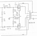
As you can see in the "before" schematic, C6 is 220uF and Rk is 250ohm/20W.
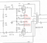
Should I just reconfigure it as shown in the "after" schematic, or should the component values change? Something tells me the caps can stay at 220uF but I am not sure about the resistors. If anything it seems like 2 10W parts will do the job but does the value also need to change?
Thanks in advance. I am also planning on doing some work to the power supply section. Currently there is basically no B+ filter other than a 470uF cap.
As you can see in the "before" schematic, C6 is 220uF and Rk is 250ohm/20W.
Should I just reconfigure it as shown in the "after" schematic, or should the component values change? Something tells me the caps can stay at 220uF but I am not sure about the resistors. If anything it seems like 2 10W parts will do the job but does the value also need to change?
Thanks in advance. I am also planning on doing some work to the power supply section. Currently there is basically no B+ filter other than a 470uF cap.
Attachments
I'd suggest you to adopt this solution for the cathode, as used by vacuumstate: Vacuum State - High End Hifi Equipment
You can see results on 3rd harmonic here:
EL84 Amp - Baby Huey
You can see results on 3rd harmonic here:
EL84 Amp - Baby Huey
Thanks for the suggestion zintolo. I actually found that schematic in my travels (among others) but the topology and component values are so different than the existing amp that I find it quite daunting, to be honest.
I should note that the main reason that I would like to do this is for tube longevity. I have read that unmatched tubes can result in runaway with the shared cathode resistor configuration if one tube starts pulling all the current for itself. I have had two premature tube failures in this amplifier and suspect that this part of the topology is the problem.
The overall sound of the amp isn't "terrible" as it is.
 Glad to help.
And if I wanted to run the tubes a little cooler, 560 ohms would do it?
What's the plate dissipation of each tube in it's current configuration?
jeff
21.46 watts each.
That's basically what I calculated based on the schematic, however I have never actually measured voltages on this amp.
Now that I understand things a bit more (after building a Tubelab SSE) and I know what to measure and how to measure it, I will do so. If the voltages and calculated currents all jibe with what is expected, then great. I suspect there might be some discrepancy.
The intention behind dropping the current / dissipation is to lighten the load on the power tansformer, which has historically run extremely hot - so much so that I installed a heat sink on the back of it and ran an 80mm fan on it.
So I probably going to want to go with 620 or 680 ohm. I'll know more when I take the measurements and do some number crunching.
Thanks. I missed the cathode voltage shown on the first schem. Is this a Yaqin amp?
jeff
Shuguang i25 (AKA Psvane TS66) - In its stock form (P-P U/L + NFB) it was rated for 25W per channel. Much more than I need.
Way back when, I replaced all the caps in the signal path, converted it to triode mode (with some help from you!), deleted the integrated USB MP3 player and hardwired the RCA inputs directly to the volume POT. I joked about it not sounding terrible before but I actually got it to be a pretty decent sounding amp.
The only real issues are the burning hot PT, a couple premature tube burn-outs, and some minor hum. I'll address the hum with some power supply filtering after I get the bias sorted.
Last edited:
Alright I've measured the amp.
B+ = 426v
k = 32v
With a 250 ohm common resistor, the current works out to .128A (128mA).
426v - 32v = 394v * 128mA = 50.432 watts
So 25.216 watts per tube.
A 310 ohm resistor in place of the 250 ohm would result in 103mA of current which works out to ~40.6 watts / 2 = 20.3 watts per tube.
So if I go with one 620 ohm Rk for each tube, that gets me the 310 ohms and 20.3 watts per tube. I'll also be drawing a total of 50mA less current on the PT high voltage tap (128mA - 103mA = 25mA * 2channels = 50mA) for a total power drop of ~20 watts through the PT.
Have I done this math correctly?
Last edited:
I was suggesting to adopt that configuration for the EL34 cathodes only, explaining the reasons.Thanks for the suggestion zintolo. I actually found that schematic in my travels (among others) but the topology and component values are so different than the existing amp that I find it quite daunting, to be honest.
Math is correct but the K voltage will rise in conjunction with the increase in resistor ohm value.So you have to remeasure the K voltage again after you change the resistor and recalculate.Alright I've measured the amp.
B+ = 426v
k = 32v
With a 250 ohm common resistor, the current works out to .128A (128mA).
426v - 32v = 394v * 128mA = 50.432 watts
So 25.216 watts per tube.
A 310 ohm resistor in place of the 250 ohm would result in 103mA of current which works out to ~40.6 watts / 2 = 20.3 watts per tube.
So if I go with one 620 ohm Rk for each tube, that gets me the 310 ohms and 20.3 watts per tube. I'll also be drawing a total of 50mA less current on the PT high voltage tap (128mA - 103mA = 25mA * 2channels = 50mA) for a total power drop of ~20 watts through the PT.
Have I done this math correctly?
Also your B+ might rise due to the lessening of current through the resistance inherent to the power supply (transformer wiring impedance ).
Last edited:
I was suggesting to adopt that configuration for the EL34 cathodes only, explaining the reasons.
I assume that the insanely large cathode bypass capacitors from the vacuum state schematic are not needed. That makes it pretty easy to try. Assuming the 620R cathode resistors, a single 82R from the junction of the bypass caps to ground should be close enough.
- Status
- This old topic is closed. If you want to reopen this topic, contact a moderator using the "Report Post" button.
- Home
- Amplifiers
- Tubes / Valves
- P-P EL34 Modification