I have some prototype boards, similar to tri-pad, with plated through holes.
I have realized that link wires need to be insulated where they cross tracks. Likewise heatsinks and possibly even component leads (0.25W resistors are pretty small & have thin leads).
Are there any online instructables to make this fiddly process look easy?
I have realized that link wires need to be insulated where they cross tracks. Likewise heatsinks and possibly even component leads (0.25W resistors are pretty small & have thin leads).
Are there any online instructables to make this fiddly process look easy?
Just strip pieces of insulation off some small wire, and put it on the lead that needs insulation.
Under heat sinks or other metal parts, use a piece of flat plastic or cardboard.
Making a prototype always requires a lot of handiwork.
Under heat sinks or other metal parts, use a piece of flat plastic or cardboard.
Making a prototype always requires a lot of handiwork.
Last edited:
Why Creating a MESS? Wasting Money, Wasting Material
We are in teh 21st Century.. Get some Simulation Program and then Test whatever you are going to build in your computer. I can assure you that you safe lots of time, Money Nerves, and what else comes with it..
After testing then get a Program to draw the layout, and there you go..
the only way that i use Test Cirquit is when i can Calculate with my Laptop.
But, I know, it's not everyone the same.. BTW I made this back in the 90ies beginning of when I did not own any computer..
Anyway good luck.
Post should acutally go to RUSSC, hit the wrong quote button..Sorry about that.
Just strip pieces of insulation off some small wire, and put it on the lead that needs insulation.
Under heat sinks or other metal parts, use a piece of flat plastic or cardboard.
Making a prototype always requires a lot of handiwork.
We are in teh 21st Century.. Get some Simulation Program and then Test whatever you are going to build in your computer. I can assure you that you safe lots of time, Money Nerves, and what else comes with it..
After testing then get a Program to draw the layout, and there you go..
the only way that i use Test Cirquit is when i can Calculate with my Laptop.
But, I know, it's not everyone the same.. BTW I made this back in the 90ies beginning of when I did not own any computer..
Anyway good luck.
Post should acutally go to RUSSC, hit the wrong quote button..Sorry about that.
Last edited:
So sad, both he and Jim Williams gone in a short time.
Bob could have ranted a long while at hpro about simulations. I won't.
Bob could have ranted a long while at hpro about simulations. I won't.
Last edited:
About Prototype board
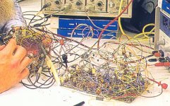
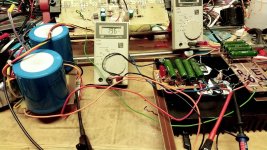
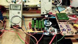
In the nineties, I Drew the circuit I was going to Test on a A4 or A3 Sheet. A4 is 21x29 cm and A3 29x42 cm .. about in these sizes.
Then I glued it down on a same size 5mmthick Plywood,
For Each connection point I used iron Nails with a bit NAIL HEAD, and used a Small Hammer to get the nails into the plywood. then used wires to make the connection, after that soldered the Resistors and Transistor on top of the NAIL HEADS, also Capacitors. and finally had an neat and clean Circuit, to look at, and to test, without to have to fear get a Wire infection on the fingers, because of cross wires all over the place..
Developing electrical Schematics and Prototypes should always be good over viewable..Check out the Pictures, and this was the start of the CLASS A SINGLE END AMP which you can look up in my other Thread..
That's my 2 cents to this and I do not press or force anyone to do so. any one should do as he's pleased with.
Enjoy Sunday..
Attachments
With the onset of super cheap Chinese pcb's I never bother with home made pcb or stripboard any more.
Anything I am not sure about gets simulated in LTSPICE.
I think I paid £0.37p each for pcb's from JLCPCB.
The postage can be expensive if you want them quick but I just use standard airmail.
Loads of PCBCAD software out there now and some is even free like Kicad.
You pays your money (or not) and takes your choice.
I expect Nigel has the right idea. 🙂
I was using prototype as generic term for such boards while actual usage is for one-off finished projects.
I will check out the jlcpcb for my next project but I am sure there will be times I will continue to use the various prototype boards.
Having recently downloaded and used TinyCAD and VeeCad for the first time I can recommend both programs but now it seems I must learn a new one for PCB design.
I was always frustrated by fiddling, cutting and stripping wires to be juuust the right length for one-off builds.
I gave up on insulated wire and switched to uninsulated, tinned wire with teflon tubing slid over it wherever needed. The teflon also works for insulating component leads etc, and it can be bought in different diameters.
See here at 6m18s for an example: Techniques and Strategies for Building Electronic Circuits - YouTube
- Home
- Design & Build
- Construction Tips
- Prototype board