SB Acoustics SB17NAC35-4 measurements!

Hi everyone,

I just want to share some of my measurements of the SB17NAC35-4 mid-woofer.

If you searching for a great performing hard cone mid-woofer, the SB17NAC35-4 is an excellent option.

Thanks to the cone geometry and shape, it has very good control of the cone break-up and it's a very low distorting driver.

It will be great fun working with this mid-woofer! 🙂

For details see: SB Acoustics SB17NAC35-4 Measurements!

/Göran

Attachments

  • SB17NAC35-4_7.JPG
    SB17NAC35-4_7.JPG
    59.3 KB · Views: 2,912
  • SB17NAC35-4_8.JPG
    SB17NAC35-4_8.JPG
    60.5 KB · Views: 2,876
  • SB17NAC35-4_9.JPG
    SB17NAC35-4_9.JPG
    62.3 KB · Views: 2,856
  • SB17NAC35-4_10.JPG
    SB17NAC35-4_10.JPG
    65 KB · Views: 2,864
  • SB17NAC35-4_1.JPG
    SB17NAC35-4_1.JPG
    65.3 KB · Views: 2,814
  • SB17NAC35-4_2.JPG
    SB17NAC35-4_2.JPG
    64.5 KB · Views: 514
  • SB17NAC35-4_3.JPG
    SB17NAC35-4_3.JPG
    60.7 KB · Views: 555

4 x BTL 300W/8R - a TDA8950j based 4 channel power amplifier

*** NOTE: latest gerbers in post # 81 *** NOTE ***


Just 4 fun I have designed (now some years ago) a 4 channel class D power amplifier to get some feeling and knowledge about building class D amplifiers.
Attached some schematics and pictures of the result.
After searching for a simple chip I found the TDA8950j which has from low to mid range an acceptable good THD performance.
The TDA8950j can be clocked externally which I have used in this design to avoid interferences of the different pwm clocks in the audible range.
Maximum output power per channel is 300W/8R.
The amp pcb is single sided and uses some smt devices to save space and to fulfill some datasheet requirements.

For DIY use only feel free to build your party power machine.😉

BR, Toni

Attachments

  • 1200x900-2012-03-04 18.25.50.jpg
    1200x900-2012-03-04 18.25.50.jpg
    58.6 KB · Views: 2,962
  • 1200x900-2012-03-04 18.51.55.jpg
    1200x900-2012-03-04 18.51.55.jpg
    155.2 KB · Views: 2,631
  • 1200x900-2012-03-12 19.26.59.jpg
    1200x900-2012-03-12 19.26.59.jpg
    128.4 KB · Views: 2,532
  • 1200x900-2012-04-01 17.28.09.jpg
    1200x900-2012-04-01 17.28.09.jpg
    122.9 KB · Views: 2,501
  • 1200x900-2012-04-01 17.32.34.jpg
    1200x900-2012-04-01 17.32.34.jpg
    215.4 KB · Views: 2,475
  • 1200x900-2012-04-01 17.33.11.jpg
    1200x900-2012-04-01 17.33.11.jpg
    198.4 KB · Views: 1,395
  • tda8950_btl_schematic.png
    tda8950_btl_schematic.png
    148.8 KB · Views: 2,444
  • tda8950_btl_schematic.pdf
    tda8950_btl_schematic.pdf
    19.5 KB · Views: 757
  • class_d_preamp_powersupply_schematic.png
    class_d_preamp_powersupply_schematic.png
    125.5 KB · Views: 1,851
  • class_d_preamp_powersupply_schematic.pdf
    class_d_preamp_powersupply_schematic.pdf
    19.6 KB · Views: 657
  • Like
Reactions: stewin

Anyone can help with identification of these B & O speakers?

Hello, bought these on Taobao. As seller says, these come from scrapped Bang and Olufsen portable audio products, but due to copyright (LOL) reasons, he can't tell me the models. I've watched several youtube videos for B & O Bluetooth speaker disassembly, and these definitely are B & O - Very similar mechanical design and marking style, but no exact match. Maybe someone can ID them? They are approximately 2.5 and 2.75 inch diameter, smaller one being marked as RADMERSPWM908402NA, and bigger one as LIDMERSPWE8164009S. The QR code on them contains that marking, nothing else.

Attachments

  • beo1.jpg
    beo1.jpg
    155.3 KB · Views: 113
  • beo2.jpg
    beo2.jpg
    160.4 KB · Views: 106
  • beo3.jpg
    beo3.jpg
    170.6 KB · Views: 109
  • beo4.jpg
    beo4.jpg
    335.9 KB · Views: 113

Tango Output Transformers

**update : This item is now sold **


a pair of tango output trans 8k : 600, decommissioned and dismounted from a working preamp.
they are modeled as 11360 because these are custom-made by Tango ISO.
Max dc current 45mA.
Asking for 500USD for the pair. These are huge and heavy, 5kg shipping weight, hence may cost quite a bit. Posting pics failed. Those who are interested in pics and shipping cost can PM me.

They are similar to the trans sold here :
NO-11360 TANGO - HiFi-Do McIntosh/JBL/audio-technica/Jeff Rowland/Accuphase There are no presence of the usual base plate as shown in the pics, because these are not off the shelf models

Philips CD-880 playing speed problem

Hi,

My Philips CD-880 playing speed is erratic. The speed it is more like holding the fast forward button. This is just by click on the play button and play the CD normally. It plays faster on its own.

On top of that, I also noticed the fast forward and fast backward buttons seem not respond or function well.

Are these issues related and am I able to fix it myself with the help of your insight? I really appreciate your thoughts!

Thanks,

usb/spdif volume is too high

I'm having another usb/spdif problem after 9 years( first one was m2tech evo usb converter +8khz 3db roll off) one of me usb converters have unusualy high output level ( chineses brezze audio xmos u8) comapring to others usb/spdif converters which have also xmos u8 chip. without changing anything on analog setup its louder by 8db. i barely can adjust digital volume on pass labs xa200.5 to mark levinson dac's in foobar- it very loud from the very begining. i have checked all three outputs of that converter -spdif/ XKLR aesbu and optical- levels are the same(8 db louder than other converters) . i always thought that spdif format output level is standartized and fixed? 😕 any way to reduce output?

Favorite Threads and Posts in "Power Supplies"

Favorite Threads and Posts in this Forum

This permanent thread is a place for links to threads or posts in this particular forum that are useful and/or exemplify the best of DIY Audio.

This is so others- especially newer members can find them. Feel free to post with these links and a brief comment on what the thread discusses. Occasionally the moderators will consolidate them into fewer posts.

Building an open embedded audio applicance.

For quite some time I have been interested in streaming direct from an embedded system to an Asynchronous DAC.

I did this many moons ago using a beaglebone, and later beaglebone black, but while the results were great - I was not entirely happy with the complexity. I basically had a custom kernel and ALSA modules. In short more than I was happy to share, and it took far more effort than the average Joe would care to undertake.

Recently however the folks behind Raspbian and especially Florian Meier with his contributions to I2S modules have made me take a much closer look at the raspberry pi - particularly "model B - revision 2". The addition of P5 and the newest Raspbian and Volumio builds make it possible to have an incredibly good I2S based music appliance by simply adding a great DAC - such as the Buffalo III-SE - which works perfectly - but you could just as well use any asynchronous I2S input DAC.

Using the raspberry pi with the B3SE is very simple. I have tested two scenarios - each with distinct advantages.

First pi -> DAC direct.

This is really simple:

just wire P5 to the DAC appropriately - as show in the attached picture. Pin 1 is indicated on the rpi by the square pin. And P5 is located right next to P1 (directly below with P1 oriented at the top).

The best news is once configured you can use the pi as an airplay receiver (with a mac) for audio (at 44.1khz) and as a direct audio appliance at up to 192/32bit sample rate (the limit of ALSA at the moment).

I have mine streaming directly from NAS (an ASUS RT-AC66U with a USB SSD drive) at up to 192Khz sounding superb! No complaints. The sound is incredible.

The second method I will introduce if there is enough interest.

Here is detail you will want if setting up Raspbian, or Volumio for B3SE.

make your /etc/modules file looks like this:

Code:
snd_soc_bcm2708
snd_soc_bcm2708_i2s
bcm2708_dmaengine
snd-soc-pcm1794a
snd_soc_rpi_dac

I am happy to help anyone who has any further questions on how to make it work.

You won't be disappointed with the results.

I have developed two different USB -> I2S modules, and I have yet to find any reason to use one of those over this much more direct approach. Especially for the Buffalo III-SE.

Cheers!
Russ

Attachments

  • Screenshot (1).png
    Screenshot (1).png
    4.8 KB · Views: 10,300

Got some AD149's and bored.

I got about 100-150 GE PNP TO3 transistors.Mostly AD149 and ASZ series. But also about a dozen 2N555


Now Ive only ever done a P3A amp to replace a guitair amp for someone.


Is there any point in making an amplifier out of these? Just for fun. I can imagine i need to figure something out to avoid thermal runaway.


I got some MAT02's that could serve as the differential front end.


I can do board design just fine, im just wondering if there is anything worthwile to build with these.

Introducing... Me? Hi!

Hi DIYAudionauts

I've peeked in on this forum on and off during my all-to-frequent searches on amps. Figured I might as well join and engage.

I'm a guitar player and have been for many moons. I predominately play blues rock/hard rock.

My main amp is a Peavey Classic 30 running through a 212. The Peavey is currently in a coma, though I think it's a blown fuse which leads me to think it's probably a power tube issue (I had noticed the overall amp volume was significantly reduced prior to the issue). I haven't been in the mood to pull the chassis and inspect because it wasn't long ago I was in there for other reasons and it's a PITA to deal with considering the folded PCB. I plan to recap it while I'm in there fixing whatever, as well as maybe replacing the tube sockets. Anyway, I'll get around to diagnosing it here in the next week or month or so.

I am by no means an amp tech expert but I'm a smart cookie and I'm comfortable with electronics (I've made minor amp repairs in the past as well as modded and built pedals and such).

I have a few other amps. I'm currently playing an Orange CR120 which I sometimes love, sometimes don't (right now we are on pleasant speaking terms) but gets the job done. I also have an Orange Micro Dark running through a 110 cab that I sometimes like better than the CR120. The gain is just a bit more pleasing on that thing, maybe due to the pre-amp being valve. *shrugs*

Lately I have been messing around with a Roland MicroCube that my fiance bought years ago but never really used (the older version, not the newest line) and I'm really kind of impressed with the 1987x setting on it and given that it's a 2watt w/ 5" speaker, I can get pretty gainy with it if I want and not worry about waking anyone up, though I generally don't have to worry much about volume issues here. It's just sometimes at say, 3am, I like to err on the side of caution.

While I love my Classic 30 to pieces I am considering the SV20H at some point or maybe even a lower wattage similar type of amp, finances and necessity providing.

I think that'll do for an intro/first post.

Cheers!

Speaker project recommendation

Hello everyone, my name is Chris.

I'm sure this question has been asked a thousand times, but I just haven't been able to find exactly what I want. I'm looking for a speaker project with plans and BOM. I can do all the woodworking, sourcing parts, etc. myself.

I have an amp that is 10watt @4ohms, so the speakers need to have decent sensitivity. Size can't be much more than 4, maybe 5 foot tall, width and depth not much of an issue. I mainly listen to classic rock from the 60s to early 80s, so I'm not needing super bass or anything like that.

Also keeping it affordable is another requirement, as my audio equipment is not high end, and I'm not an audiophile. My current speakers are over 40 years old as well as most of my setup. They sound good to me, but could be better. Any suggestions, or resources for a project would be greatly appreciated.


20210206-180543-2.jpg


This is my current setup.
Fisher Studio Standard, Receiver RS-2004A, Cassette-8Track Deck ER-8150, Turntable-Linear Motor 120 Pole MT-6224,
Amp-MP PureTube

Is High Frequency Switching Noise Worth Filtering?

I'm working on designing an op-amp based headphone amp, and I'm currently working on building the power management section of the circuit. I'm using a +/- 12V switching split power supply, which is then fed into +/- LDOs - LT3080 and LT3015. I can see on my oscilloscope that both the pre- and post- regulated power signals have high frequency ripple, about 75mV peak-to-peak @ 100Mhz. This makes sense since the LDOs have very poor ripple rejection at such a high frequency.


My question is, is this signal worth filtering? In my mind, such a high frequency signal is way out of the audible range and thus shouldn't affect the output of the op-amps in any audible way. However, I admit that I'm a bit of a novice when it comes to the power supply side of things, so I could be overlooking something obvious. Thanks in advance!

Regulator for Pre-amp

Hi folks

I've built a pair of this simple JFET pre-amp, substituting a BF256B for the BF245B and a 2SA1175 for the BC560.


I'm wondering how to power them, what sort of regulator to use, there are so many options from the humble 78xx IC to really complex fully discrete circuits.


I'm not sure how exotic a regulator this circuit needs to sound good, I like the idea of a discrete circuit rather than an IC, but would that be overkill for this pre-amp?


Is there a discrete circuit that offers better performance than a 78xx or LM317 that is pretty simple with a fairly low parts count?


I'm open to suggestions and in need of guidance.

Attachments

  • jfet_simple_preamp-8b38574.png
    jfet_simple_preamp-8b38574.png
    84.9 KB · Views: 1,194

DIY amp recommendation for B&W 684 S2 speakers

So im looking to build my first amp from scratch to power a pair of BB&W 684 S2's. I've got quite abit of experience repairing older amps, and I own a pretty complete electronics lab too as im studying EEE at university.

I almost want to design my own from scratch, but at this point i think class AB BJT power amps have little room for re-invention.

Any ideas what so ever are very welcome! thanks!

Volume Pot and Preamp

I am thinking about buying Aiyima A07 and pair it with the preamp below. For convenience volume would be controlled via the preamp:

Dayton Audio WBA31 Wireless Wi-Fi & Bluetooth Audio Receiver with IR Remote

My questions are:
  • Does the volume pot impact sound quality? Because I will have a preamp, am I better off removing the volume pot?
  • Alternatively I can consider buying an amp board without volume pot
  • If I turn the Aiyima volume pot all the way up, would it be similar to having no volume pot at all? Or am I better off leaving the volume pot about half way up?
Thanks in advance.

Hickok 750 owners help!

Hi,


got a fairly nice tester that had some previous work on it, and for a reason there is an alone loose wite going nowhere?
Of course it does have to be related to the Short selector, but where it should be connected?


From the facing plate this wire is on the 4th deck of the shorts selector.
It is white/black stripe.
From ohmeter measurement it connects on position 3-4-5 to the same 4th deck going to a red wire that is connected to R21 , a 47 ohms resistor on the screen selector.


A bit of search yes helping with the schematics, but still parts are unidentified inside the Hickok 750.


either this wire was cut? Or it is going to a nearby selector, switch ot post, it is actually about 6 inches long, so it cannot acroos the whole tester??


See the pictures...


Otherwise the 49 small bias fuse light bulb is burned. Trying to find some replacement.
I could do line test fine, so meter circuit id OK.
But cannot test a 6L6 for Gm or emission, no needle mouvement...

Attachments

  • 20210301_104202.jpg
    20210301_104202.jpg
    1 MB · Views: 178
  • 20210301_104257.jpg
    20210301_104257.jpg
    1,010 KB · Views: 148

Diy Build Guides

I was looking around on the “new under construction” Diy Build guide page to see if any projects had been added, and saw a new build guide for the “Starving Student II” headphone amp/linestage by 6L6? However, None of the links for the DiyStore or threads work with a message of “page not found” error when clicked. I’m assuming this is another great project soon to be available since the build guide seems ready to go? Looks like a good one! Any teaser info would be great 6L6!

Attachments

  • 880130ED-8071-4415-B0DB-3D44AD6823CF.jpeg
    880130ED-8071-4415-B0DB-3D44AD6823CF.jpeg
    315.4 KB · Views: 418

Interfacing with phantom power, Project 66

Sorry in advance that this is a mish-mosh of questions. I added numerals to paragraphs to aid peoples responses.


The main subjects of inquiry surround these questions:
A:How do I pull power from pins two and three (48v and 0v) to create a symmetrical supply to juice an (in this case) op amp and bipolar transistors?


B:How do I protect the devices from phantom power?


So I've made a mic pre based on ESP P66. I had some questions which were answered after I posted about it in the forum
Mic pre Project 66 negative swing clipping
Now I have new inquires, although while these relate directly to this project, they're much more generally applicable concepts. I'm going to attempt to get them out as cogently as possible. Pretty much all “statements” should have question marks all over it.


1.I've sketched out most pertinent parts of all the circuits in here using www.falstad.com/circuit which I find to be a very helpful little app.


2. I might not even use phantom for this project, but I'd like to know how, and in any case being able to protect a device from phantom seems like a crucial ability.
Regarding phantom power in general Do all mixers provide the same amount of current? If the max power available is 48V/6,810Ω=0.007, so ~7mA, not a lot of power to work with. Does anyone know current draw for a variety of phantom powered devices? I recapped a CAD E200 recently, the active compliment in there is an OPA2107, a pair of TL062 and three TO-92 devices- it gets around the current limitation with two internal 9V NiMH. Shure SM81 has no additional power source with six active devices in it (a to-92 j-fet and five SOT23 BiPol transistors-a guess)


3. Generally speaking, the capacitors in series on the signal lines are there to block the DC, but not to protect the devices? The value of the cap determines low frequency roll off? Assuming “electrolytics in the signal path is sub-optimal” wouldn't film caps be a good choice (if their larger size can be managed)?


4.There are a number of schematics that incorporate diodes for what I gather are protection purposes, but the designs are all different. I can't find any clear and widely used schematic of phantom protection, and powering an op-amp/active device from phantom.


5.Some use Zeners, some small signal 4148/914, others 4XXX or I-don't-know-what.


6.The various orientations of the Zeners is particularly confusing to me- some have the "inside pair" cathodes directed to ground (FIG2A, FIG1), some pointed away (FIG6, FIG8)


7.I "understand" that the Zeners are clipping diodes, so for a 12V Zener, if a 15V (since the AC signal is riding along with the DC, do both AC and DC get "clipped"??) appears across a signal line and ground, the Zener will limit the voltage to ~12v.


8.ESP, which I usually find very informative is not elucidating anything for me. In FIG 3, are the op amps running off of +-12, provided from the 24V Zener D5 then split via the resistor divide R12/R13? D3 and D4- I have no idea what they're doing.


9.FIG 9 uses 1n914. Only protecting, not powering?


10.Fig 7 seems to be pulling power off the signal lines using 4 diodes(signal diodes?); powering but not protecting?. No idea how this works as drawn.


11.The only thing that makes sense to me is FIG 5 (my sketch). all 12V Zeners oriented the same way, power is drawn from “12+ and -12”, signal lines continue past the non-polar caps.


I could make this longer and longer, but hopefully I've revealed enough of my confusion that I can get help unraveling it.:drunk:-->🙄-->😎


One PDF I couldn't attach due to limit was TI “Phantom power with operational amplifiers”
https://www.ti.com/lit/an/sboa320a/sboa320a.pdf?ts=1614850698210&ref_url=https%253A%252F%252F


Much appreciated.

Attachments

  • Fig 2a.jpg
    Fig 2a.jpg
    49.3 KB · Views: 78
  • fig 3 active di ESP.jpg
    fig 3 active di ESP.jpg
    59.5 KB · Views: 75
  • Fig4.gif
    Fig4.gif
    11.5 KB · Views: 75
  • Fig 5.jpg
    Fig 5.jpg
    30.6 KB · Views: 73
  • Fig 6.gif
    Fig 6.gif
    87.6 KB · Views: 77
  • Fig 7.gif
    Fig 7.gif
    45.8 KB · Views: 57
  • Fig 8.png
    Fig 8.png
    29 KB · Views: 56
  • Fig 9.jpg
    Fig 9.jpg
    32.4 KB · Views: 59
  • THAT mic pre phantom.jpg
    THAT mic pre phantom.jpg
    239.2 KB · Views: 54
  • 48V_Phantom_Menace.pdf
    48V_Phantom_Menace.pdf
    152.9 KB · Views: 104

Potentiometer body grounding odd behaviour

I've an equaliser that uses 8 B100K pots and the bodies are grounded back to SG even though it's fine without. The circuit has a small buzz but what is odd is that when I place my finger on the wire linking the pots, the buzz disappears. Is there any way to replicate my big finger with caps, resistors or diodes back to ground?

At times when I poke around with my finger in some circuits I get a hum but I've never had one where it shut up any noise. Most circuits I've built never needs the pot body grounded but when required I use the SG on the pot PCB. BTW, it's in a plastic case so no chassis grounding used.

Attachments

  • RZ_pot_geq.jpg
    RZ_pot_geq.jpg
    53.6 KB · Views: 301

What size sealed box for 2 JL subs?

I'm looking to build a single chamber, sealed sub box for 2 JL Audio 10w6v3-D4 subs. However, the box is going in the back of a c6 corvette where I also need to store my top on occasion. So, the box must have a fixed width and height. The only variable is the depth.
If I use 3/4 mdf, the outside width is 28.5" and the outside height is 10.5", what's the best depth the box should be for an optimal tune? The last suggestion was 11". (How is the punch affected if that's either too deep or not deep enough?)

(Each sub is powered by its own JL Audio 500/1)

Telefunken RGN4004

I have two of these made at some time for Wehrmacht service, stamped BAL716, the whole nine yards what ever that means. I've been saving them for my 'ultimate' amp because they are so incredibly beautiful. But I see them going for fantasy amounts on ebay. There is one on ebay at the moment for $2150!!!
KL77305 KLANGFILM TUBE Big BLACK MESH RECTIFIER RGN4004 TELEFUNKEN NOS rgn2504 s | eBay

Soooo. I think my ultimate amp can be just fine with a set of 5U4s or the like.

But seriously. Are these really worth such hideous amounts of green? Not that I mind, but I have no intent on ripping off the filthy rich (who else buys $2k tubes?) I dunno, if these are super rare, and ceertainly - they are gorgeous, so perhaps they are worth a **** loads?

Thanks for any comments.

Lastly, is there any point in even trying to sell them here on this forum? Or are these only ebay bait? Not that I am greedy, but I am not about to give them away now that I see they obviously are rare and precious.

Thanks for any inputs.

Attachments

  • 855resize.jpg
    855resize.jpg
    90.7 KB · Views: 332
  • 855resize2.jpg
    855resize2.jpg
    235.2 KB · Views: 307
  • 855resize3.jpg
    855resize3.jpg
    265.3 KB · Views: 307

stk4192 very low to no output left channel

Hi, I have a amp with STK4192 , the circuit track is broken feeding the left channel but if i run a wire connecting it, it only hums like a short, even touching the cap feeding the left side hums bad and the right side is fine,
if the amp is damaged would input side play up like it is ?

touching a wire to the left channel input cap gives a big crack on the speaker but the right working side does not do this.

Brett

OUTPUT fets heat up, why?

Original fets were FQP34N20
- 200V
- 31A
- 2370 input capacitance
- 75milliOhm RDS


I replaced them with IRFB31N20D.
- 200V
- 31A
- 2400 input capacitance
- 82milliOhm RDS


Gate resistors are 47ohm.


Attached is a photo of the switching wave of the output fets. There are 2 banks with 4 mosfets in each bank.
Right now I put one mosfet in each bank to test.


The fets heat up a little bit. The switching of the fets looks good? Or do I miss something here 😀

Attachments

  • PHOTO_20210304_142227.jpg
    PHOTO_20210304_142227.jpg
    795.5 KB · Views: 89

Negative versions of TLV431 and TL431 regulators

Every now and then I come upon a situation where I want a complementary version of the TL431 or TLV431. I was setting up SOA limit protection for an amp and I found myself wishing for one. Then I realized how they are designed inside, and it's not that hard.

This is a circuit that maintains its reference with respect to the cathode, unlike the TL431, which maintains its reference with respect to the anode. Then it pushes current out the anode instead of pulling it into the cathode.

I haven't simulated it, but it looks like it should work. If you try it and it doesn't work, let me know.

Attachments

  • NegAdjShuntReg.png
    NegAdjShuntReg.png
    78.1 KB · Views: 450

Roksan Blak CD player - serious fault...

Recently I got a Roksan Black CD player on my bench, for some modifications/improvements. So, I have found out about a serious fault, either a design fault or a production fault... In my opinion it should be a production fault, which it should definitely be cached by the final tests of these products out of the production lines. But it was not... It seems to me that these CD players are sold out so, as the one I got, and this is not good...

The post DAC circuits on Black CD player it are designed and build to be powered by standard (LM7815/7915) fixed regulators. The I/V stage it should be powered by +/- 15v regulators, as the buffer opamps as well. I appreciate this design as a good one, being able to ensure a high quality output signal. Well, maybe not just the best choice for these fixed regulator devices, but anyway, good enough.
The problem here is that all these regulators mounted on board (see picture), it get on their inputs 14,5v. On the output pin of these regulators I measured +12v and -13v... This is very wrong! All these regulator devices it not regulate anything!
The toroidal transformer used to power these devices it is not properly made to deliver the right voltage or power so that the 15v regulators get a higher voltage on their inputs (at least +/-17v unregulated DC), so to be able to do their regulating function. The consequence of this fault is the all post DAC opamps it are powered by fully unregulated DC.
Here is not about a possible power fault on board, which it may cause an over current, lowering so the voltage delivered by the transformer. The toroidal transformer it is just not made/designed to deliver more voltage on this winding output. Why Roksan have used a such faulty transformer? How it happened that nobody have measured the voltages in this area on the production lines (voltage test points are provided on board)? For sure this fault is not singular, being specific to a singel product. This is a production line or product design fault! I just wonder myself how Roksan it can sell out such devices...
I am thinking to warn here the owners of a such CD player about this fault.

Attachments

  • RoksanBlackCDplayer - Analogue power.jpg
    RoksanBlackCDplayer - Analogue power.jpg
    370.7 KB · Views: 1,085

Is it possible to use AD1866 or AD1851 in NOS DAC

Hello,
I have searched the forum, but with no answer to my question. I am a beginner in digital technology and just seeking help. I am 58 years old and tried to stay away from building DACs, but I heard a lot of good opinions about NOS DACs. I would like to try take on the project. Since, I am bound at home, not COVID related, I went through my part boxes and found the following: AD1866N, AD1851N and AD1892 JR chips. The DAC chips are in DIP packages where AD1892 is SOIC. Is it possible to build NOS DAC with these chips?
Thank you for the help !!!!!!

Bragi - 2 way Mass loaded Transmission line for Scan Speak drivers and wave guide

Over the last 50 years I have been building a number of speakers (Elsinore as the last one) as well as totally renovating lots of speakers (lastly Rauna Leira and Rauna Chorus/Vale). Now i have decided to build a Mass loaded Transmission Line speaker (TMLTL) from scratch, which is kind of new to me.

The decision on the below setup is based on a number of reasons such as sound stage, previous experiences, cost vs performance, physical appearance etc.

If anyone would like to join in the process you are more than welcome.

The basic cabinet calculations is done by the award winning (and very humble) Transmission line expert (which he refuses to call himself) 
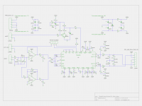
Paul Kittinger (google him) in Martin J Kings software MathCad. That software is unfortunately not available anymore due to misuse by comercial users. The work has then continued in Hornresp, which is a great software, with almost the same result. The filling calculations are based on somewhat slightly different methods in the two softwares which create the slight differencies in outcome. The results has been explored back and forth and ended up with minor changes but pretty much the same as from the beginning with Paul and MathCad.

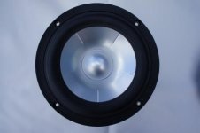
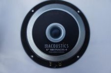
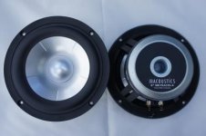
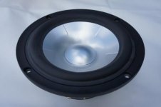
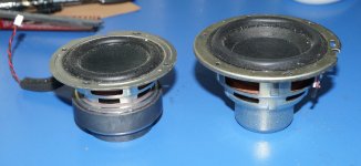
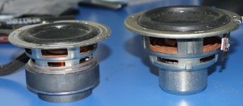
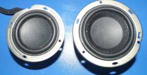
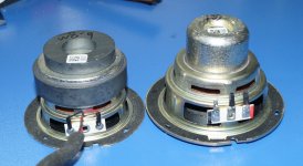
For midbass a number of Seas, SB Accoustic and ScanSpeak drivers has been up for discussion, exploration and design ending up with the by many highly appreciated SS D8531G00. The SB Accoustic SB17NRX2 (or MFC) will do as a budget alternative with minor changes to the design (according to simulations both in MathCad and Hornresp).

For the tweeter there could be a number of alternatives, up to high cost super tweeters. Although bot in comersial speakers as well as in the DIY world the mid price section seem to offer a number of very good alternatives from Seas, SB Accoustic, Peerless and ScanSpeak. Following the diyaudio Elsinore project for many years including the comparison of different tweeters there, I ended up with the SS D2608/91300 together with a waveguide as a starting point. This also very much from building one pair of Elsinores, helping a friend with one pair, and still having some pairs of wave guides in the basement. Hopefully it´s also where it will end up. The Elsinore is a 2,5 way speaker with a higher XO point to the tweeter. But hopefully the tweeter/WG combination will work with the lower X/O point in this design.

The basics looks like this:
- Mass loaded, Transmission Line (MLTL)
- Coupling chamber at the throat of the line(Inspiration Rauna Leira)
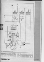
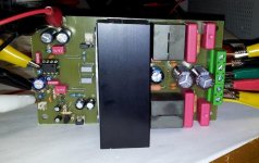
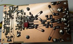
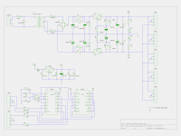
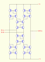
- Fairly simple 6/12 dB cross over (Xmachina + Xsim, Vituixcad)
- X/O point somewhere 2,3-2,8 kHz,
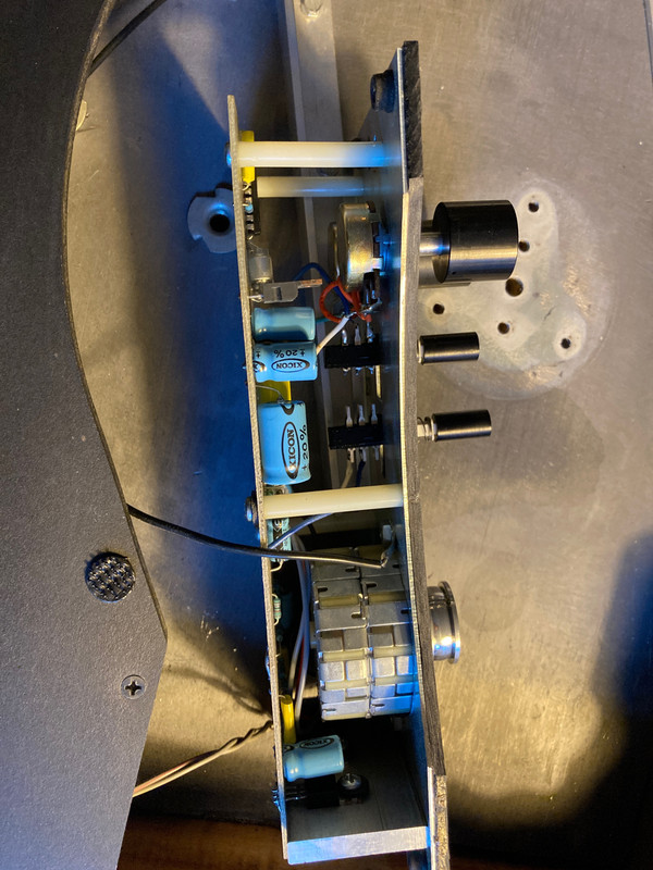
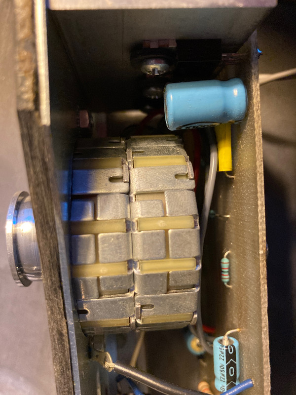
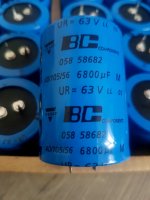
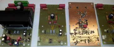
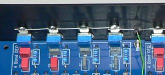
- Fairly standard/cheap components in the X/O (maybe except for one JA Superior Z-cap, the red one)
- 2 way with 2 drivers
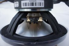
- Tweeter SS D2608/91300
- Waveguide for the tweeter (from the Elsinore project here at Diyaudio)
- Midwoofer SS 18W/8531G00
- About 100 cm/40" in height, as narrow as possible
- Bass -3dB at about 32Hz Hz and -6dB at 28-29 Hz
- Partly tilted baffle
- Two versions - Four (std type of box) or six sided cabinet (inspiration Rauna Vale / Opus3 Chorus)
- MDF furniture quality, 25mm for the cabinet, 19 mm for the internal divider
- Cross over placed at the lower back of the cabinet for easy adjustments
- .......

The cross over will be based on actual measures with the drivers mounted in the cabinet. The measures will be done at different speaker positions (0,5 to 4 piradians). The software for the cross over will be explored with a number of supporting people, and softwares such Xmachina, Xsim and/or Vituixcad, REW and/or Arta etc.

Project started autumn 2020 and will continue slowly forward. Inspiration, comments, contributions etc are very welcome.

ES9028Q2M driver for Raspbian based distro

GitHub - VinnyLorrin/Rpi-ES9018K2M-DAC

Only tested on ES9028Q2M DAC, current known issue located at post#57

To use,
1. copy 'es9018k2m.ko' to /lib/modules/4.9.79-v7+/kernel/sound/soc/codecs/
2. copy 'rpi-es9018k2m-dac.ko' to /lib/modules/4.9.79-v7+/kernel/sound/soc/bcm
3. copy 'rpi-es9018k2m-dac.dtbo' to /boot/overlays/
4. execute 'depmod -a'
5. add 'dtparam=i2s=on', 'dtparam=i2c_arm=on' and 'dtoverlay=rpi-es9018k2m-dac' to /boot/config.txt, and remove the old DAC overlay entry.
6. reboot.

The code is developed based on GitHub - SatoruKawase/I-Sabre-K2M: Audiophonics I-Sabre K2M DAC Board ALSA Driver. The register definition is based on GitHub - luoyi/Rpi-ES9018K2M-DAC.

Enjoy

:cop: Attachment removed by moderation as requested by OP

10 russian KP926A

Hi.
I have 10 russian KP926A V-FETs for sale at £17 each plus shipping.
I would prefer them not all to go to the same buyer, so please give others a chance.
I will do my best to copy the original Russian data sheets if required at cost.

Attachments

  • IMG_20210225_125252.jpg
    IMG_20210225_125252.jpg
    732.5 KB · Views: 462
  • IMG_20210225_125311.jpg
    IMG_20210225_125311.jpg
    561.6 KB · Views: 460
  • IMG_20210225_125549.jpg
    IMG_20210225_125549.jpg
    337.2 KB · Views: 439

On-wall DIY design

Hi

Anyone that have a good on-wall DIY speaker design to recommend?
Looking for something that is bot to large in size.

To be mounted on my daughters room. 16 years old, but not mutch into what is good vs bad quality. However, I am and would like here to be used to how good sound should.

Maybe also a small sub (8-10") to give the fundation if we do not belive the speakers will be enough alone.

The AKSA ' 'TLP' - a great solution to a digital issue! :-))

The 'TLP' is a tube buffer which Hugh produced before he developed his GK-1 preamp ... which then led on to the GK-2, which I have. So it's a product from long ago ... which languished, after the GK-1 came out. 🙁

Now, I have just dipped my toe into the digital waters ... replacing the 3-way analogue active XOs I've been using with my Maggies for 15 years with a miniDSP unit (10x10Hd). I did this because I added a pair of subs to my Maggies, so:
1. I needed a 4-way XO, and
2. I needed to use DSP to delay my Maggies, to line up with the subs which are about 1.3m further away from my ears.

As a result, I have just bought 2x TLP kits! 😎

Now, my system currently is: sources --> GK-2 --> miniDSP --> power amps.

The beauty of the GK-2 is that it has 2 outputs:
1. the ss (sub) output. (This bypasses the unity-gain tube output stage of the GK-1/GK-2.)
2. the tube output.

If you are running active speakers, it is a well-known fact that you should feed your woofers from the 'sub out' and your tweeters (& mids) from the 'tube out'. The reason is:
* ss out gives better definition of the leading edge of bass transients (than the tube does), and
* tube output gives a more entrancing delivery of mids & HFs than the sub out does.

So currently:
* my sub out feeds subs + bass panels, and
* my tube out feeds mid panels + ribbons.

This is fine ... but as the next component in the signal chain is my miniDSP unit, it is possible I don't hear the full beauty of the 'tube out' coming from the speakers that I did when I had analogue active XOs? 🙁

So I am going to re-arrange my component chain and remove the GK-2. This is not a simple exercise as I need to have:
* source selection, and
* volume control.

My component chain now becomes:
* phono stage ---> ADC
* 4x digital sources (phono ADC / CDP / DAB+ tuner / Foxtel box) to digital source selector (Audio Authority 1177A-1)
* output from 1177A-1 ---> miniDSP (digital input)
* 8x RCA outputs from the miniDSP 10x10HD ---> an 8-channel volume control (DIY "Relaixed", out of Holland)
* 8-channel output from the Relaixed volume control --->
-- 4 channels of TLP, for mids & ribbons ---> power amps
-- 4 channels direct, for subs & bass panels ---> power amps.

So, this way, I should really be able to hear the 'tubeyness' of the TLP, as it is directly feeding the mid & ribbon power amps ... in contrast to my current situation where, really, I am "listening to the sound of" the miniDSP output DACs (which cannot be very good, given the price of the miniDSP!).

I will report back when it's all come together! :cheers:

Andy

Assistance adding a 4 ohm/ 6 ohm switch to crossover

TL;DR: I'm looking for some help understanding a circuit design, and where to place a switch on a crossover.

I few years back I built a pair of Roman Bednarik's Microbe in a 2.5 way MTM. At the time Roman had offered a standard 4ohm and a tweaked circuit 6 ohm design for those with less efficient power sources. Since that time I have a power amp and would like to add a switch to go between the two.

I'd like to add a switch to the crossover to bypass the 2 ohm resistor, however there appears to be an LRC also included in the high efficient design. Roman seems to have moved on and is no longer reachable, so I'm not sure if the LRC was added as part of the efficient design, or if this was some other improvement added later. The Microbe's were a design that was always being tweaked and redone, so one theory is that perhaps that LRC was added as part of some "improvement" between the original and the high efficient version.

Links to speaker workshop files of the High efficient version: http://rjbaudio.com/misc/Microbe 2.5 way MTM w-2ohm.JPG

The original design lacks the 2 ohm resistor, but also the 400uH/8ohm/15uF LRC circuit before the 3mH inductor. Does this need to be bypassed? Why is it there, but not in the original?

I'd appreciate any help out there. I would need a dumbed down explanation of where to add a switch if that is the best option. I can see that I'd probably need a 1.2mH inductor and switch to make this work.

Thank you

Solution/device needed for simple home theater

I have an LG OLED 65" TV.
I have a cable box and an Apple TV as source inputs connected to the TV.
I don't need or want additional inputs.

The TV has both an optical audio output and an HDMI Audio Return Channel (ARC) output.
I want to add four external speakers in a configuration that Magnepan has promoted (see: Magnepan)

MC1_02.jpg


center -- left -- TV -- right -- center.

In this configuration the pair of center speakers delivers center speaker sound in applications where one does not otherwise have room above or below the TV for a normal center speaker.

I have powered speakers (with passive crossovers) available to use.

I need a solution/device that can take as an input one of the TV's available audio outputs and then send the proper part of the signal to each of the four powered speakers.

I don't need an AV receiver. I just want something simple.

Thoughts and guidance appreciated.

Amplifier advice needed please.

I was going to build a new set of subwoofers but I've changed my mind.
I think that using the old Cerwin Vega Vega 124's in 45 litre sealed boxes will do in the short term.
The problem I had using them was simply the lack of bass boost where it was needed.
My tops are using a decent enough Vifa 10" as the mid bass and using passive sealed the CV were not reaching deep enough.
Bass and subwoofer amps from the commercial sector are now so cheap and so powerful and have DSP that I don't think it makes sense not to use something I already have and use DSP for the performance I want and need.
The Vega 124 has just enough excursion at 19mm [ 38mm P2P] to take some DSP at ~30 Hz where I think it's needed.
I have some idea of what's needed but not enough to make an informed purchase. Budget wise I can afford something like a Behringer
I want a 2 channel amp for the stereo subs but as I already use a cheap Behringer XO for the signal split from the pre-amp I may not need integral crossovers in the sub amp
The drivers should be able to handle 250 watts easily and I'm not allowed to play my music that loudly anyway
Any advice for a cash strapped speaker builder with mainly old school gear?

connecting denon dvd3930 to denon avr 4306

hello i have 2 question regarding a denon dvd3930 connection to avr-4306 receiver to tv

question 1

i read that the digital to analog converter in the dvd3930 is better then the one in the 4306 receiver.

so i thought 6 analog cables from the dvd player to the avr receiver.

but then i saw the denon link option i assume they would only add this if this is the superior option.
this would keep the signal digital to the receiver but has me confused what is the best way to connect.

question 2 regarding video

should i go

dvd hdmi reciever
reciever hdmi to tv

1 extra step seems like more distortion compared to

dvd hdmi tv.


what would be your advise for connecting the dvd/receiver/tv
hdmi/spdif/denon link/analog

your help is highly appreciated.

Kicker ZX1000.1 11.29.2005

Does anyone have a schematic for a kicker zx1000.1? This one is the 2005 edition. Came in with blown outputs. Replaced them and checked everything out on low power. All was ok.

Did a high power test and Q106 and Q108 (output transistors) blew again.

I replaced one of the outputs with one I had here. Now with no load once again, I can get the max rail to rail on the speaker terminals when turning up the gain. Once I connect a load I don’t get very far and the speaker outputs go straight to square. Is there a common problem with these amps? Before I started my test, the output inductor was sort of loose. I used some E6000 on a spot on the bottom to hold it in place. What did I miss?

Noise on one channel of PPI A600

I have a Precision Power A600 which is giving me a scratchy "static" sounding noise on the left channel. The noise is there almost all the time and does not go away if I unplug the RCA input cables, and also the volume of the noise is not affected by the gain control on the amp. I still hear it just the same if I turn down the gain all the way.

The channel still functions when the audio inputs are connected, and the output sounds OK except that there is always this fixed level of noise present.

I checked out the board to make sure there weren't any obvious broken solder joints near the inputs, and everything looks OK. None of the components look burnt or damaged.

I've noticed that there are quite a few PPI experts in this forum, so I'm hoping someone can help me track down this issue or suggest someone competent who could fix it.

Thanks very much for your help!

Bryan

Hi from Upstate NY!

Hi all,

noob from the Ithaca area here. I’ve been lurking and thinking about building my own audio equipment for quite a while. At first primarily speakers but lately I’ve been thinking about starting with one of the amplifier kits. I’ve been considering the ACA, Akitika and Icepower kits, but wonder if I should start with something really basic to develop my soldering skills first. I’d love to get some input on that and maybe some suggestions for smaller projects. I’m finally joining after years of lurking because I now have some space to set up a comfortable work area and am starting to assemble equipment. Thanks in advance for all the help. Hopefully I’ll eventually be able to contribute myself.

craig

Looking for Alps 50k Stereo pot

Looking for suppliers who stock Alps pots as i cant find the version i need. I know it exists as i can find pictures of them on google images, but no working links.

I need a 16mm 50k stereo linear taper, with an extended round shaft. The original one has a dead spot that wont come back, tried cleaning it, working it back and forth, no dice.

Attachments

  • 20210218_125544.jpg
    20210218_125544.jpg
    967.5 KB · Views: 81

Negative feedback loop , issue with different op amps

I just made simplest possible full bridge class d amp where i have triangle oscilator,two comparators and full bridge output....also i made negative feedback loop using op amp.Feedback loop is made in basic mode as diferential amplifier.All is made as basic school example class d model.Please dont ask for schematic because it is as simple as i said.Amp works great and output noise is ultra low.When i connect negative feedback loop ( i can easy change op amp ) it works....gain is going down and all works fine.Issue happens at saturation and clipping.If i use LM358 as feedback op amp i have high pitch cracling at clipping (low power but noticeable).... if i use NE5532 i have serious crackling (high power).....If i use nothing and i remove negative feedback loop i have excelent sound and no cracling on clipping.I know that op amps i mentioned are two worlds....but among all i tested these two works fine.


I tried to lower input levels on both inputs of diferential amplifier design-didnt help.I tried to do various compensations - no luck.Main difference between these two op amps is that LM358 can swing output to ground and NE5532 cant....this pushed me to decrese input levels even more.....didnt help.Any idea is welcome.I will test and publish results.

Sota TT Motor Board Mishap

I realize that Sota doesn’t publish schematics and such and given that, it may be tough to help me, but trying anyway. . .

A friend just picked up a Sota Sapphire II with a Series IV or V upgraded motor. The seller had cobbled together a power supply using a HP computer wall wart, which worked okay.

But the cobbled part came uncobbled and the lightly soldered connections between the 30V DC wall wart wires and the wires going to the Sota motor board got reversed (!!) and a puff of smoke resulted. Reversed the wires the way they should have been and tried again, and another puff of smoke appeared.

So the questions:
- Is the motor itself likely still okay?
- What component/s are most likely to have been blown by that initial 30v reverse voltage?

I’m going to try and help him repair the motor board, and we’re willing to go down the brute force shotgun path of replacing every component if needed (and probably will do all the electrolytic caps in any case since they look original), but if someone can point to the most likely components to be blown in a reverse bias scenario, that would be very helpful.

Couple of pics attached so I’m not making any faulty assumptions on what motor we’re dealing with here.

4-A44-CB35-B966-4247-AD66-59-E0-C5-E665-BC.jpg


BC6010-C7-7476-4-B80-A39-F-1187728-B9-ECB.jpg

Electrocompaniet EC-3 MC preamp Service Manual wanted

Deal all fellow members,
I am looking for Electrocompaniet EC-3 MC preamplifier Service Manual. I recently bought a used one but the previous owner had sent the unit to a non professional technician (actually a bad technician...), who removed some parts from printed board and lost them! As you can understand, Service Manual is mandatory to put this unit to life again.
Thanks in advance for your kind attention and help.
Regards,
John

ETI Hybrid EL34 amplifier

I came across this old article the other day and also discovered that I have a lot of the components in my spares bin.

I've got a pair of Hammond 1650H output transformers. I'm not sure if they are a perfect match for this circuit ?

YES. I'm aware that there is a mix-up in the capacitor values and voltages but I can play with those.

Has anyone built this from 1992 ?

Attachments

  • Image123.jpg
    Image123.jpg
    949 KB · Views: 886

Power Long Life Snap-In Vishay 6800uF 63V 10,000 h at +105 ° C

Nichicon 150,000uF 63V --- Vishay 6800uF 63V --- TE connectivity 1R 200W

Capacitors Nichicon LNR1J154MSE Screw Terminals
150.000uF / 63V 76,2 x 140mm
date code: 1628
1pc - 40€/pc
2pcs - 35€/pc
4pcs - 32€/pc

Price on Mouser about 85€/pc, DigiKey even more expensive.
https://www.mouser.sk/ProductDetail/Nichicon/LNR1J154MSE/?qs=kArNe9LFxXki%2BZy9xERD/w==
Blocked

Great for Leach 2x200W with common power supply and similar amplifiers 🙂


12pcs power resistors 1R - 200W HSC2001R0J - TE CONNECTIVITY.
10€/pc
https://sk.farnell.com/cgs-te-connectivity/hsc2001r0j/resistor-200w-5-1r/dp/272681


Shipping and packaging about 15€ in the EU. (Sent from Slovakia)
Payment by bank transfer.

Attachments

  • Eohy2NE.jpg
    Eohy2NE.jpg
    290.7 KB · Views: 318
  • U27zrEn.jpg
    U27zrEn.jpg
    171.4 KB · Views: 313
  • 0meZxvp.jpg
    0meZxvp.jpg
    201.1 KB · Views: 310

Advice on standalone rpi/DAC player

Hallo all,

For some time I've been thinking it would be good to give my CD player (a venerable Rotel RCD965BX) a rest and try using a standalone digital media player.

There don't seem to be too many things like this available ready-made at a reasonable price, so I'm thinking of putting together a non-network-attached headless audio player based around something like a (2GB ram) rpi 4b and a hifiberry dac pro +, using a local usb drive to store the music files, and maybe a cheap 7 or 8 inch tablet for a remote. It looks like this is possible using Volumio for example as it appears you can set it to be a wifi access point for the tablet.

I would be very grateful for any advice and recommendations. There may well be obvious flaws in my plan that I have missed (for example, whether the OS & usb drive would be ok with being powered on and off using the psu switch without throwing up filesystem errors). If it is do-able, I'm wondering what the user experience would be like (how long it would take to boot, how easy to navigate my music collection using the tablet, and suchlike). It'd probably cost me £150+ for the bits, a significant amount for me, so it would be nice to know in advance what sort of thing I could end up with for that. I imagine the SQ will probably be sufficient for now as my system isn't too high-end and I can always play with different DACs etc. in future.

Thanks in advance.

Constant base voltage on transistor tester project.

I am designing a transistor matcher and curve tracer.

Got it running sort of ok.
Measures hfe of npn and pnp ok and compares well with my DMM for readings.

I then tried a darlington npn transistor and the hfe is 31 !

I assume base voltage doesnt change when checking hfe.
My base current comes from base driver voltage (through 1k resistor) - base driver voltage at transistor turn on divided by a 1k resistor.

It seems with a darlington the base voltage goes up as its driven harder.
This messes up the calculated base current.

So I am having to add a differential amp across base resistor to calculate accurately the base current.

Seems odd it works fine with none darlington or low hfe transistors.

There is a problem with high hfe none darlingtons too.

Waiting for a new pcb now to see how well it works.

To brace or not?

Attached are the cabinet plans for a kit I just built. It sounds very good and I'm not detecting cabinet vibration with music, meaning no excessive upper bass warmth and the cabinets "disappear" properly and form a solid image. However, with such a large box, in your experience, would bracing be beneficial? Or since it sounds good, just leave it be?

Attachments

Projects by fanatics, for fanatics
Get answers and advice for everyone wanting to learn the art of audio.
Join the Community
507,783
Members
7,888,271
Messages

Filter

Forum Statistics

Threads
406,232
Messages
7,888,271
Members
507,783
Latest member
ys.zhu