I've been into DIY audio for more than 35 years and its time to give something back to the community...
You're free to use the provided information for your own personal projects but not for any commercial business.
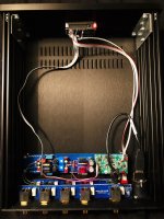
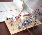
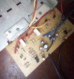
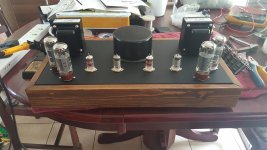
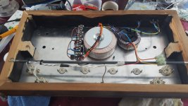
For the fun of it I made myself an everyday control unit...
Highlights
- B1 rev 2
- MUSES 72320 volume
- Relay based input
- SilentSwitcher power supply
- Hypex voltage regulators
- LED dot matrix display
- Arduino microcontroller
- Apple remote control
- Open source code
- Case for the control unit.
A YouTube video as a teaser can be seen
here.
Let's dive deeper into each area mentioned above:
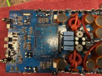
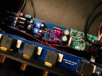
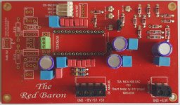
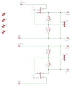
1. B1 rev 2
I designed by own printed circuit board with the following features:
- Optional input and output coupling capacitors (on board bypass jumpers)
- Optional MUSES 72320 volume
- DC-adjustment
- Prepared for use of (Hypex) voltage regulators
- Prepared for use of the brilliant SilentSwitcher.
I'll later provide the PCB files for production and recommend a PCB manufacture that works for me.
(I've a few boards available, send me PM, first come, first served.)
More info about the B1 rev 2 can be found
here.
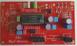
2. MUSES72320 electronic volume
The volume control is based on
NJR MUSES 72320
Passlabs use this as volume control in their top preamp(s?).
As Passlabs I only use the first attenuator and I've no buffer in front so the impedance of the input is in the range of 14-20 KOhm according to the
datasheet.
The schematic and PCB layout will follow in a later post...
I'll also provide the PCB files for production and recommend a PCB manufacture that works for me.
(I've a few boards available, send me PM, first come, first served.)
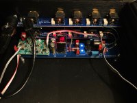
3. Relay based input
Samuel Groner and Bruno Putzeys published a short article with measurements in Linear Audio Vol 13. The article can be bought online
here.
After I read the article I couldn't chose any other relay than what Bruno Putzeys use in the mola-mola products...
🙄
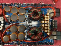
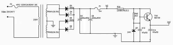
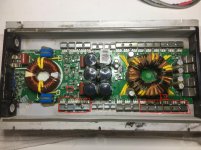
4. SilentSwitcher power supply
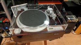
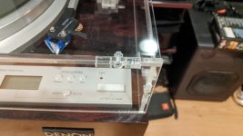
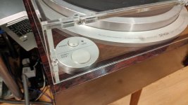
A brilliant low-noise DC-DC voltage regulator designed by Jan Didden. I use it for everything possible even for my Well Tempered Amadeus turntable!
There's a diyaudio thread about the SilentSwitcher
here.
You can buy the SilentSwitcher in the diyaudio store
here.
5. Hypex voltage regulators
The original SilentSwitcher outputs +/-15 Volt and I had to lower that a bit and I chose the low-drop out
regulators from Hypex.
My PCB for the B1 is designed with Kelvin sense connections to provide point-of-load (local) regulation without requiring physical proximity of the Hypex regulators.
You're can also use ordinary 3-pin voltage regulators or chose the SilentSwitcher MKII that can be customized to output +/-12 Volt and skip the extra voltage regulators.
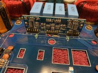
6. LED dot matrix display
I chose a LED dot matrix display as they're readable on distance even in very bright light. The drawback is switching noise from the multiplexer has to be handled.
To keep things as simple as possible I chose a display kit from Adafruit:
Adafruit 0.8" 8x16 LED Matrix FeatherWing Display Kit - Red
And to make the mounting of display easy I chose to solder some short female headers on the microcontroller board:
Short Feather Headers Kit - 12-pin and 16-pin Female Header Set
7. Arduino microcontroller
The microcontroller is an
Adafruit Feather 328P - Atmega328P 3.3V @8 MHz.
USD 12.50... what not to like?
😀
8. Apple remote control
The control unit is remotely controlled by an
Apple Remote
I just love the small Apple aluminium remote. I also use it for my main preamp (Vacuum State RTP3D) and my friend and fellow diyaudio member
Fonnesbek made the c code for it at the time.
Most of the code for the Apple remote in my control unit discussed here is based on the code made by
hifiduino. I just made it work on the Arduino. I might publish the Arduino code itself on Github.
I made the code for auto-pairing the Apple remote to the control unit so where would be no conflicts with other Apple remotes in the same room.
The first time the control unit receives an IR code after powering up that specific Apple remote is locked to the control unit.
The pairing is lost when the microcontroller loose its power. A clever move if you think a little about it.
9. Open source code
Beware that I'm not educated in programming so ugly hacks is to easily found in my code. That said I find the code bug free and highly usable.
I'll make my source code available on GitHub in the near future.
You're free to modify and fork it into your own edition when credited to me (and including 'hifiduino' for his code used for the Apple remote).
The source code shall remain open source and may not be used for any commercial products what so ever.
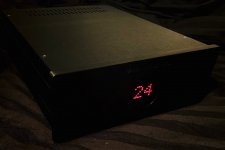
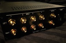
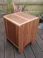
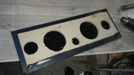
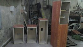
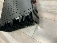
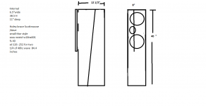
10. Case for the control unit
I use a well known all aluminium case from Hifi2000 in Italy.
- Hifi2000 Galaxy Maggiorato GX288 230 x 280 mm, all panels are aluminium
- Hifi2000 Galaxy Maggiorato 10mm front panel, black
- Custom CNC machined panels: front, back and bottom
- Discrete text on the front panel (black in-fill color)
- Easy readable text on the back panel (white in-fill color)
- 1 mm clear pipe for the red LED on the front panel.
- All metal work made by a professional company in Germany to my specifications.
- Red perspex is press fit into the front panel.
I'll provide the CNC files that are needed to modify the original hifi2000 case.
--
More information to follow in the days to come.
If any of the provided information is faulty or can be optimised for an even better end user experience feel free to post your comments.


 This thread was split from another. Split begins here.


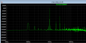

 . But there seems to be a not so small improvement.
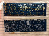


