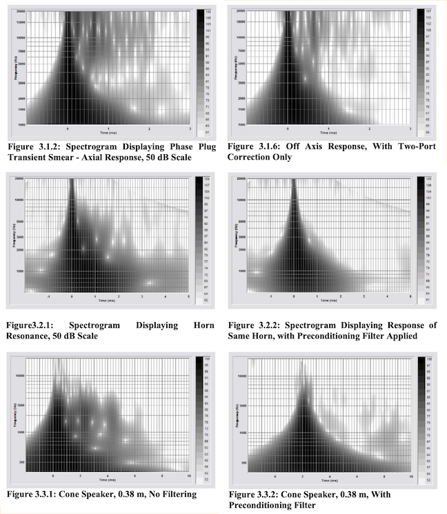
So my interest was sparked by this AES paper: Improving Loudspeaker Transient Response with Digital Signal Processing. It deals with designing specific FIR filters, they call them Preconditioning filters. The idea is that you can correct certain aspects of your speaker that are not dependant on listening position (this is a vastly oversimplified explanation). This should be especially of interest for compression drivers and horn resonances but might apply to other stuff as well:
The only thing that the paper actually does not tell us is how these filers are actually created. So that's where you guys come in. How do you think this can be done by the average DIY'er?
The only thing that the paper actually does not tell us is how these filers are actually created. So that's where you guys come in. How do you think this can be done by the average DIY'er?
Attachments
I read this paper years ago and had the same thought, would like to get some more insite on the options.
the one obvious one is taking a large amount of mesurements spatially, if you average all the mesurements then you'll be left mostly with the common problems. then you just invert this response or use a tool (eq. REW eq window) to design a filter.
my personal experience with engineering papers (electronic engineer) is that they probably didn't include the method because it was boring, or they didn't take a very rigorous approach with it, so they dont want to have their subpar method exposed.
my personal experience with engineering papers (electronic engineer) is that they probably didn't include the method because it was boring, or they didn't take a very rigorous approach with it, so they dont want to have their subpar method exposed.
That is not only the case with electronic engineering. Many computer science papers are also like this. It's quite appalling what people get away with. Churning out many papers is often more important than actually delivering any quality.
In this case, however, it's more like protecting some intellectual property. Why go into great detail about how time smearing in a compression driver phase plug occurs (talk about boring..) and then say nothing at all about how the filters are actually created?
It can be educational to read this paper, but I don't think there's as much to it as there seems. When you look at what cannot be fixed, it is just like we already know. It may take us some time, but we can get there on our own.
I wouldn't have accepted this paper (also Electronic Engineer), it reads more like an advertising blurb for some proprietary method.
to me this suggests that the method may be to simulate structures like the phase plug to extract a 2 port network that is used to make a correction filter?
It is better to develop corrective filters by targeting specific subsystems which are LTI two-port subsystems. Filters to correct each of these subsystems can be developed from their measurable dimensions and parameters, or by painstakingly separating the response of the subsystem from the response of the overall system
to me this suggests that the method may be to simulate structures like the phase plug to extract a 2 port network that is used to make a correction filter?
Last edited:
Or just math in some cases like the phase plug? Assume half energy is passed through phase plug slot (best case) and half stays in the cavity for another few millimeters, easy to calculate?😀 There was a thread few years ago Measuring horn reflections back into the throat where some of this stuff is pondered but at least I gave up then for the sake of easier problems. Interesting topic.
I looked at this briefly. First thing I'll say is that they make a big deal out of their spectrogram. But like frequency response, CSD, etc, if the system is LTI, then everything you need to know about the system is in the impulse. Take the horn resonance example. Use the initial impulse response they show, apply and FFT to get frequency response, F(s). Define some reference response that you want to achieve, T(S) and from the two you can write
T(S) = PRE(S) x F(s)
and
PRE(S) = T(S) / F(S).
Now, take the IFFt of PRE(S) and you have the impulse response for PRE(S). Then there are many ways to convolve PRE with the input signal either in the time or frequency domain to achieve the corrected impulse they show. No matter what they say, that is all they are doing. It's just a matter of how the define F(s) , single point or specially averaged measurement, and T(s). Today all that is done with the click of a mouse using programs like the Ultimate Equalizer.
Hi guys,
@ tmuikku, ha! that horn reflection thread was fun. You and nc535 did some really cool work in it, and i learned the power of simple impulse inversion....which brings me to...
@john k... so glad to hear your comment. I have come to the same conclusion, that in the end it's just impulse inversion. But i don't have the technical chops you do, so it's good to hear some confirmation.
Experientially, I've been able to look at the impulse response of FIR filters that Fulcrum Acoustics provides for their speakers. It's pretty cool how they provide DSP settings for so many prosound processors / processing amps.
Anyway, all that i have looked at fit in a file of 384 taps @48 kHz.
They've used various impulse centers in the vicinity of 2ms FIR processing time....so like a hundred taps into the 384 count, and are not centered for linear phase.
Impulses show small corrections that look like they could be roundtrip reflections within the horn...or mouth gack..who knows.
But bottom line i think, is that the corrections are just a single impulse inversion.
If the files are indeed multiple measurements taken at say throat and mouth, each inverted and then convolved together somehow, that would be something special i guess.
But i just don't think so...
BTW, in the thread tmuikki linked, post # 153 gets to how to use REW to make impulse inversions Measuring horn reflections back into the throat
A continuation of that post is here REW as FIR generator experiments
@4real...that would be an easy way to play with making these kind of FIR file corrections, if you have a FIR processor
Yep, it doesn't matter what you call it. Ultimately the system to be corrected is treated as a 2 port, LTI system and it and it's correction are defined by a simple impulse. I suspect if you wanted to you could model amplitude effects by assuming that at a number of discrete amplitudes the system was quasi LTI and define a series of corrections and them have a 3-d map (x = filter frequency, y = filter amplitude/phase, z = input amplitude) and have the correction change with input level. When you consider the level of processing that is done for digital video, what is done in audio is trivial. Probably because it's just not worth doing. Of course, with audio it would cost $10k to get such a digital processor with capability a small fraction of the processing you find in a $300 flat screen 4k TV. LOL.
Cool so we can just take the compression driver and measure it naked on the bench, design an FIR filter (say using rePhase) that eliminates the resonances observed in the responses and this will be valid when connected to the horn?
I'm presuming that directly inverting the response in this case would not be desirable because flat frequency response from the naked driver is not desirable.
In terms of practicalities would just measuring centered over the phase plug at a few multiples of the throat diameter suffice?
I'm presuming that directly inverting the response in this case would not be desirable because flat frequency response from the naked driver is not desirable.
In terms of practicalities would just measuring centered over the phase plug at a few multiples of the throat diameter suffice?
Hey John, may i ask you a couple of things...
First one....it seems to me there can only be one unique impulse response for any given frequency response....that the FFT to IFT back and forth equivalence demands this.
Is this correct?
Second one, about FIR filter frequency resolution.....
where resolution is specified as F = 1/time length of filter.
An example: a 384 tap @ 48kHz commonly used in prosound, with impulse centering, would have a time length of 192 samples or 4ms.
This gives a frequency resolution of 250Hz.
What exactly does the frequency resolution mean?
250Hz seems awfully coarse to do any good other than high in freq.
Is resolution simply the ability to apply correction when and where the filter is altering mag and/or phase?
IOW, is it just about, how much Q the resolution can handle?
Because I know from a/b'ing music through a very short 50 tap FIR file that applies zero correction...where it's just passing flat mag and phase...that no difference can be heard at all.
Thanks !
And sorry i haven't taken the time to learn how FIR coefficients actually work...been too busy building and trying stuff lol
Kipman, I think Gunnes hints about it multiple times (there is some fulcrum audio content in youtube as well) that the sound only partially entering the phase plug slots makes the very high frequency anomalies and could be implemented just by measuring physical dimensions and maybe little experimentation to get level right. But once the sound is in the throat it is another matter, don't know how to measure the reflections from there. He is demonstrating the phaseplug thing with huge 4" vc compression driver. I'm not sure if it is relevant with the smaller CDs or with the modern ring radiators.
Throat and mouth reflections could be minimized making a good waveguide (see the ATH thread). Fourth thing that is left is the cone driver edge resonance thing. That would be fun thing to figure out 🙂
Throat and mouth reflections could be minimized making a good waveguide (see the ATH thread). Fourth thing that is left is the cone driver edge resonance thing. That would be fun thing to figure out 🙂
Last edited:
Cool so we can just take the compression driver and measure it naked on the bench, design an FIR filter (say using rePhase) that eliminates the resonances observed in the responses and this will be valid when connected to the horn?
I'm presuming that directly inverting the response in this case would not be desirable because flat frequency response from the naked driver is not desirable.
In terms of practicalities would just measuring centered over the phase plug at a few multiples of the throat diameter suffice?
Hi kipman,
i don't think we want to design a FIR filter for the naked driver...
Not sure what value that brings.
But a corrective FIR filter for the driver on chosen horn makes complete sense...i believe that's all Fulcrum is doing....
I'm never really sure at what distance though. I like to average a few on and mildly off-axis measurements, at either 1m from mouth indoors or 3m outdoors .
I take the response to flat
(other than adding in a house curve, which is something i do in a separate stage of EQ, because i'm always changing my mind about house curves...and flat speaker tuning doesn't ever change on me 😀)
Hi guys,
@ tmuikku, ha! that horn reflection thread was fun. You and nc535 did some really cool work in it, and i learned the power of simple impulse inversion....which brings me to...
Hahaa yeah that was so much fun I must have giggled out loud 🙂
Hey John, may i ask you a couple of things...
First one....it seems to me there can only be one unique impulse response for any given frequency response....that the FFT to IFT back and forth equivalence demands this.
Is this correct?
Second one, about FIR filter frequency resolution.....
where resolution is specified as F = 1/time length of filter.
An example: a 384 tap @ 48kHz commonly used in prosound, with impulse centering, would have a time length of 192 samples or 4ms.
This gives a frequency resolution of 250Hz.
What exactly does the frequency resolution mean?
250Hz seems awfully coarse to do any good other than high in freq.
Is resolution simply the ability to apply correction when and where the filter is altering mag and/or phase?
IOW, is it just about, how much Q the resolution can handle?
Because I know from a/b'ing music through a very short 50 tap FIR file that applies zero correction...where it's just passing flat mag and phase...that no difference can be heard at all.
Thanks !
And sorry i haven't taken the time to learn how FIR coefficients actually work...been too busy building and trying stuff lol
First let me say that I've been out of this for years now and really only looked at it when I was helping with the development of the Ultimate Equalizer. ot a pro, 🙂. That said,
1) Yes.
2) Right, resolution basically sets the limits of low frequency filtering. A rule of thumb seems to be, as I recall, filters should be limited to 3 x time the frequency resolution. So 250 Hz would suggest filters at 750 Hz and above. For low frequency filtering you can use more taps which places higher demand on processing, or use a lower sample rate for low frequency LP filters since the higher frequencies of the input would be in the stop band anyway. Both are done depending on the purpose.
3) Consider what the impulse of a flat filter is. It's just a time delay with coefficients, ....0,0,0,0,1,0,0,0,.......where the delay would be the related to the sampling rate and the number of zeros before 1. So sample length really doesn't matter. The only difference between in and out would be noise associated with the processing.
Thank you John, that all makes sense.
I was near certain about 1),
just wanted to remove any doubt, because it says alot to me about the different tuning methods to get to a given acoustic target .....
how the methods have to end with the same electrical transfer function to achieve the acoustic target.
I've heard the same rule of thumb, about staying 3X above the frequency resolution.
Seeing the flat filter coefficients, it's easy to gather what is going on...pure delay.
An aside...I recently nabbed a more powerful used Q-Sys processor on the cheap. Am currently running 8 channels of 16k taps for one pair of 4-ways speakers, and another 8 channels of 4k taps for a second set of different 4-ways....all at the same time with 25% of processing resources remaining.
Playing with mixed phase, to gain even further frequency resolution down low.
It's awesome the audio processing gear available now...but like you say.. still whooped by an everyday TV! lol
I am thinking along the same line about the impulse responses. The tricky parts could be how to handle any 'division by zero', how to approximate the result in a FIR filter with a reasonable length and how to make the correction robust, as loudspeakers are not LTI when ageing or being driven hard.But like frequency response, CSD, etc, if the system is LTI, then everything you need to know about the system is in the impulse. Take the horn resonance example. Use the initial impulse response they show, apply and FFT to get frequency response, F(s). Define some reference response that you want to achieve, T(S) and from the two you can write
T(S) = PRE(S) x F(s)
and
PRE(S) = T(S) / F(S).
Last edited:
If your taking swept sine measurements, then you've already rejected the non LTI components.
in trying to replicate this kind of thing with tweeters in horns I just took many anechoic measurments in the horn listening window and then averaged them.
I tried inverting this, and also tried minimum phase equalisation. honestly I didn't hear any improvement from going from the minimum phase -> full inversion. FYI I used REW for this. the measurement math options will let you do all these kinds of things.
if you just average many measurements, my experience is that there will be no zeros in the passband. if you think about the system, that makes sense. you'll only really have zeros in a non anechoic measurement.
I am thinking along the same line about the impulse responses. The tricky parts could be how to handle any 'division by zero', how to approximate the result in a FIR filter with a reasonable length and how to make the correction robust, as loudspeakers are not LTI when ageing or being driven hard.
It's a simple matter to limit the bandwidth of the correction. Look at Apendix B, which I wrote, of the UE manual. https://www.bodziosoftware.com.au/Ultimate_Equalizer_Manual_5.pdf
Kipman, I think Gunnes hints about it multiple times (there is some fulcrum audio content in youtube as well) that the sound only partially entering the phase plug slots makes the very high frequency anomalies and could be implemented just by measuring physical dimensions and maybe little experimentation to get level right. But once the sound is in the throat it is another matter, don't know how to measure the reflections from there. He is demonstrating the phaseplug thing with huge 4" vc compression driver. I'm not sure if it is relevant with the smaller CDs or with the modern ring radiators.
yes, I have seen the youtube video with the compression driver. I was thinking though that the fraction entering the 'wrong' slot would be the same with or without the horn though so the filter could be designed using a naked driver measurement. I guess I would have to try it to know.
Performing FIR correction of a complete horn+driver is not unique/new and the paper specifically says that extracting the features they want to correct from complete system measurements is difficult (to paraphrase).
*I also tune my speakers to flat in a freespace or groundplane and then correct response in room and apply 'fun' EQ ontop of that.
Last edited:
- Home
- Loudspeakers
- Multi-Way
- Preconditioning FIR filters, how do you make them?