So I've salvaged two 350 VA 26-0-26 Vac transformers from two defunct German Leslie clones that had two power amplifiers each.
Now I'm thinking of re-using the two power transformers. As supply rails of +/-35 Vdc yield to just moderate output power and don't utilise the trannies' full power capacity, I'm thinking of connecting the secondaries in series to get rails of +/-70 and +/-35 Vdc and building a stereo pack of class g or class h amplifiers. Are there any designs that are worth building?
And what's the best PSU configuration? Should I stack four 10 to 22 mF/50V 'lyrics in series, or is it preferable to have a separate grounded 'lytic for each of the four rails?
Best regards!
Peter S worked through a defunct Peavey GPS3500 on PA-systems forum last year. He posted the schematic on that, but the diyaudio feeble search function doesn't seem able to find it. Turned out okay, he repaired it.
I suppose one could dial back the 24 output transistors of that design to a 350 watt/ch amp, but I don't quite see the point except as a mental exercise. 140 v transistors like 2n6340 2n6337 aren't significantly cheaper than MJ21193-4 and don't come from as reputable a semi house as On either. My datasheet on that part is from boca semi. There should be a lot of recalculation of resistor values and zener reference voltages.
Warning that schematic has an inscrutable NE5517AN IC, which might be unobtainable: except in a blown up Peavey GPS3500 from E-bay. I checked the US e-bay site, blown up Peavey amps are quite scarce today.
The schematic of the rectifier cap board of that unit was not posted, so what Peavey did with their transformers & capacitors is a mystery. They had a shop building dual secondary winding transformers already for products like the PV-1.3k, so they could probably buy anything they wanted.
Last edited:
Douglas Self discusses the development of a basic class G amplifier in a separate chapter contained in most editions of his Audio Power Amplifier Design handbook. There's plenty of help and even PCBs (see link, though these are relatively expensive) and ideas for building a power amp. with around the power levels suggested by your transformers. Preview here.
If you look on the Crown website I believe they have some of the service manuals for the older pro amps that use 2 or 3 level power supplies. Even the still manufactured today cdi series amps use this design technique to improve efficiency at high power levels. Yorkville also has schematics online for their amps which are noted to be very reliable.
You could also build a fully balanced amp with +-35volt and get the higher power you want.
You could also build a fully balanced amp with +-35volt and get the higher power you want.
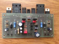
you may use the attached design. i designed it to be used it in an active speaker for the LF amp.
Amp module for 2 way active speakers
Regards,
Aniket
Amp module for 2 way active speakers
Regards,
Aniket
Hi,
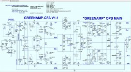
check out ostripper's eco version, with class G output stage. Looks promising!
GreenAmp ++ modulated Class G output
Sajti
check out ostripper's eco version, with class G output stage. Looks promising!
GreenAmp ++ modulated Class G output
Sajti
Last edited:
They have exactly the same efficiency. But in class H the dissipation is confined to the lower set of transistors - when the rails switch the main outputs go back into a high dissipation mode. In class G the dissipation is handed off to the upper set of modulation transistors. It is the same number of watts, just in a different place.
Class H will in practice have slightly better efficiency when clipping, because the total saturation voltage will be lower... by a volt or two. In really big amplifiers with parallel upper transistors, the voltage drops in their emitter resistors can be an extra 5 volts, favoring class H where one single big .005 ohm hexfet will do the job.
Class H will in practice have slightly better efficiency when clipping, because the total saturation voltage will be lower... by a volt or two. In really big amplifiers with parallel upper transistors, the voltage drops in their emitter resistors can be an extra 5 volts, favoring class H where one single big .005 ohm hexfet will do the job.
Class H is widely confused with Class G but the opposite is the case. Class G switches and class H modulates the rails. ref. Power amplifier classes - Wikipedia... Class G defines modulated high voltage supply rails, while class H switches them, right?....
Class H is widely confused with Class G but the opposite is the case. Class G switches and class H modulates the rails. ref. Power amplifier classes - Wikipedia
But Doug Self in the 5/6th editions calls it G. Self's Signal transfer kit is "G".
And Apex here on the forum calls the (900W) switched rail project "H".
OEM's have this problem , too. Emotiva's CPU controlled switcher is called
G.
ESP has it right , Power Amp Classes .
A lot of confusion out there.
Perhaps "G" is more infamous , better for marketing.
OS
CFA + "modulated G" H ....
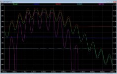
Ahh , This is better - with a CFA input stage.
-No outer stage switching
-Same PPM ultra-low THD as with a triple output stage
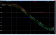
-Tracking up to 200Khz , soft clip , no saturation - period.
-Based on the slewmaster triple output stage with the refined Crest CFP.
The last distortion mechanism is the low rail diodes. Careful selection of
a soft switching schottkey eliminates this.
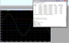
Scaled up to 8 devices , this design should match the Crest 400/700W
rating ... BUT maintain .003% THD20k.
- Input stage has been built , EF3 inner OPS has been built , Crest enhanced
rail trackers should work ... hit the simulations with every stress available .
OS
Hi,
check out ostripper's eco version, with class G output stage. Looks promising!
GreenAmp ++ modulated Class G output
Sajti
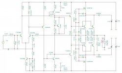
Ahh , This is better - with a CFA input stage.
-No outer stage switching
-Same PPM ultra-low THD as with a triple output stage
-Tracking up to 200Khz , soft clip , no saturation - period.
-Based on the slewmaster triple output stage with the refined Crest CFP.
The last distortion mechanism is the low rail diodes. Careful selection of
a soft switching schottkey eliminates this.
Scaled up to 8 devices , this design should match the Crest 400/700W
rating ... BUT maintain .003% THD20k.
- Input stage has been built , EF3 inner OPS has been built , Crest enhanced
rail trackers should work ... hit the simulations with every stress available .
OS
Attachments
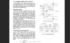
Have a look at the service manual for the Pioneer A80.
I agree with you , I just decided on "modulated class G".
Pioneer , toshiba , many other older Japanese designs tried
this design technique.
I actually simulated that pioneer and others. Not "transparent enough".
They also had 70's diode tech , no simulators to wrap a transitional compensation
scheme around the trackers.
Most of the old designs could not even come close to the plain EF3 that i compared
this one to.
PS - I fooled around with about 50 class H (g) designs from the 70's to
present ... Including some proprietary topologies. I tried to weigh simplicity
with performance.
OS
Just 4 should give 200/400W.How many output devices would be needed for this design work with the OPS itself and for the modulated part to make a 200watt 8ohm system?
Maybe more if 4 MT-200 sankens are used.
Each of the 4 devices would have almost max DC SOA of 17A !!
An 8 device MT-200 might approach 1KW , unreal.
Edit - normal listening would require 1/2 the heatsink (or half the heat)
as your normal EF OPS.
Power supply requirements would be 60% of the EF.
Example - 2 channel = 300VA 18-0-18 + either a 60-0-60 600W SMPS
or 800VA 45-0-45.
PSRR is -110db on these amps.
OS
Last edited:
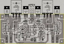
Sorry, but there are errors in APEX HX11 schematic.
Diode z1 is directly polarized while z3 is indirectly polarized. This will connect zener z3 to lower power supply probably completely destroying it in the process. Also, there is a bav21 diode in series with 1k resistor which is shorted.
Diode z1 is directly polarized while z3 is indirectly polarized. This will connect zener z3 to lower power supply probably completely destroying it in the process. Also, there is a bav21 diode in series with 1k resistor which is shorted.
Last edited:
Sorry, but there are errors in APEX HX11 schematic.
Diode z1 is directly polarized while z3 is indirectly polarized. This will connect zener z3 to lower power supply probably completely destroying it in the process. Also, there is a bav21 diode in series with 1k resistor which is shorted.
Also T10/T15 have emitters swapped with collectors.
PCB is ok though.
- Status
- This old topic is closed. If you want to reopen this topic, contact a moderator using the "Report Post" button.
- Home
- Amplifiers
- Solid State
- I'm in search of a class G or H amplifier design