The clamp diodes either need to be eliminated, or the sources of the FETs need to connect to the BJT collectors thru a fast diode (same type as the mid rail commutator). I use the diode anyway on all modulated rail designs (ok to eliminate with switched rail which typically uses a drive circuit which minimizes the possibility of reverse or over biasing the gate-source). And the resistor-diode string needs to go to the rail, rather than being shorted.
The H900 is a good working design from Apex, but it was more geared toward PA use. There are quite a few documented builds - by now all the bugs and mistakes have been worked out of the posted schematics and PCB layouts.
The H900 is a good working design from Apex, but it was more geared toward PA use. There are quite a few documented builds - by now all the bugs and mistakes have been worked out of the posted schematics and PCB layouts.
NAD 3240PE is a nice class G amp. I have one that I’m rather fond of, having fixed.
DIY includes repair? NAD 3240PE advice needed...
DIY includes repair? NAD 3240PE advice needed...
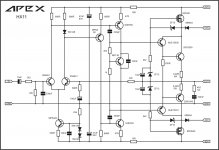
Sorry, but there are errors in APEX HX11 schematic.
Diode z1 is directly polarized while z3 is indirectly polarized. This will connect zener z3 to lower power supply probably completely destroying it in the process. Also, there is a bav21 diode in series with 1k resistor which is shorted.
There are still more errors:Also T10/T15 have emitters swapped with collectors.
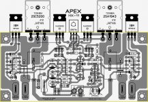
PCB is ok though.
- T8 emitter and collector swapped
- BC546B's at 80 Vdc rails?😱
- BC639's, BC640's, BD139's and BD140's at +/-80Vdc rails?? 😱😱 (edit: as said by saijti before...)
Best regards!
NAD 3240PE is a nice class G amp. I have one that I’m rather fond of, having fixed.
DIY includes repair? NAD 3240PE advice needed...
I am impressed. NAD actually stabilized the impedance of the tracker (Q439) ,
uses the EF3 for the inner pair , addresses Ccb (C433) at the tracker driver ...
They did not make Q431/435 non-switching or snubber the old /slow low rail
diodes.
Still , this NAD is the closest to "hi-fi" I have seen for a 20th century class
H. Definitely worth repairing. NAD could realistically do .01 -.03% THD.
Thanks for the "lead" (NAD schema).
Never seen/heard about this one.😱
OS
Attachments

Hi Kay
You never said what speaker load you want to drive? You might be better off replacing its passive crossover with an electronic one and multi-way amplification. This would allow the treble amp and even the mid amp to be lower power, maybe withing the rails provided by the PTs. For more power you could bridge the amps and use low rails.
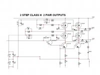
The usual multi-tier supply uses ONE PT with symmetric taps on the secondary. This makes best use of the energy handling of the PT.
Filter caps are usually stacked with protection diodes across each tier, but this is likely for cost and space saving. There is likely an advantage for hifi performance to having at least some of the filtering be ground-referenced for each rail.
The mosfet tier switching with the "look-ahead" floating supplies for their gates works extremely well - easily as good as the more complex switchers people have tried and use. One thing to add is a 100nF ceramic from floating rail to floating rail. This eliminates tiny distortions at low signal level in simulations I've done.
The pro amps you see with high-power ratings often list an unqualified THD that is pretty low, but this is 1kHz at 1W. At full output the world turns upside down and THD is not a lot less than 1%. I've seen class-G amps that maintain <5ppm at 20kHz at full output even in 2R loads. These are a hybrid design designed by a friend of mine, so I can't disclose the schemo, but the output is at the limits of the wall socket.
The point of class-G for home use is to avoid clipping by having extreme head room. Sure it's nice if clipping is soft or controlled, but how about avoiding clipping altogether?
You never said what speaker load you want to drive? You might be better off replacing its passive crossover with an electronic one and multi-way amplification. This would allow the treble amp and even the mid amp to be lower power, maybe withing the rails provided by the PTs. For more power you could bridge the amps and use low rails.
The usual multi-tier supply uses ONE PT with symmetric taps on the secondary. This makes best use of the energy handling of the PT.
Filter caps are usually stacked with protection diodes across each tier, but this is likely for cost and space saving. There is likely an advantage for hifi performance to having at least some of the filtering be ground-referenced for each rail.
The mosfet tier switching with the "look-ahead" floating supplies for their gates works extremely well - easily as good as the more complex switchers people have tried and use. One thing to add is a 100nF ceramic from floating rail to floating rail. This eliminates tiny distortions at low signal level in simulations I've done.
The pro amps you see with high-power ratings often list an unqualified THD that is pretty low, but this is 1kHz at 1W. At full output the world turns upside down and THD is not a lot less than 1%. I've seen class-G amps that maintain <5ppm at 20kHz at full output even in 2R loads. These are a hybrid design designed by a friend of mine, so I can't disclose the schemo, but the output is at the limits of the wall socket.
The point of class-G for home use is to avoid clipping by having extreme head room. Sure it's nice if clipping is soft or controlled, but how about avoiding clipping altogether?
There are still more errors:
- T8 emitter and collector swapped
- BC546B's at 80 Vdc rails?😱
- BC639's, BC640's, BD139's and BD140's at +/-80Vdc rails?? 😱😱 (edit: as said by saijti before...)
Best regards!
HX11 schematic
Attachments
HX11 schematic
330pf miller capacitance ... wow.
UG point must be 100k !!
Surely this design could be better at 68p or something reasonable.
OS
330pf miller capacitance ... wow.
UG point must be 100k !!
Surely this design could be better at 68p or something reasonable.
OS
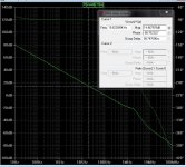
I use HX11 for subwoofer, it can work with 33pF miller for FR speakers.
No NFB at ALL 330p @ 20khz.
Would be alright as a sub amp , with a wide margin - HX11's class H
would be audible at the mid/high's.
Even using my simulations , this would be true in real life.
14db at 20K is way short of the amps global gain , NFB does not "kick in"
down to 8 Khz. good sub amp ..
OS
Would be alright as a sub amp , with a wide margin - HX11's class H
would be audible at the mid/high's.
Even using my simulations , this would be true in real life.
14db at 20K is way short of the amps global gain , NFB does not "kick in"
down to 8 Khz. good sub amp ..
OS
Attachments
Last edited:
I use HX11 for subwoofer, it can work with 33pF miller for FR speakers.
As a sub amp , this is ideal.
The cheap MOSFET also makes this nice . Still , look to my H design ...
No switching , high 20K gain margin (10+db) ... unity gain out to 2.25mhz.
I would actually use an HX11 for my sub , but greenamp all the way for
full range or biamped use.
Just a few components could refine HX11 , even for sub use.
OS
Last edited:
Class H deserves just a little sophistication.
Since there is positive feedback in the OPS , more can go wrong.
Simple should be reserved for an EF2 or lateral OPS.
I have noticed a "slacking' in designs lately.
We are dealing with deadly voltages and expensive speakers.
DIY does not have to be sloppy.
Think worst case , give a design "headroom" . I have had builders
do wrong parts/fake parts. NO big smoke screen , just wrong voltages.
We have to "raise the bar " , the true engineers on the forum laugh at
our ignorance. We can't have that !!😀
OS
To answer some questions that have just arisen:
- I'm planning for 4 to 8 ohms loads.
- Bi-amping is a no-go for me. I'd like to keep wiring as simple as possible.
My available power transformers come from wannabe-Leslies with two 80 watts amps on board, though. I don't want to re-use these, due to their '70ies designs with two pairs of slowish BD245/246 power devices and BD241/242 drivers each.
Best regards!
Over 3 600 000 views...Class H deserves just a little sophistication.
Since there is positive feedback in the OPS , more can go wrong.
Simple should be reserved for an EF2 or lateral OPS.
I have noticed a "slacking' in designs lately.
We are dealing with deadly voltages and expensive speakers.
DIY does not have to be sloppy.
Think worst case , give a design "headroom" . I have had builders
do wrong parts/fake parts. NO big smoke screen , just wrong voltages.
We have to "raise the bar " , the true engineers on the forum laugh at
our ignorance. We can't have that !!😀
OS
YouTube
Last edited:
Over 3 600 000 views...
YouTube
I did not say/imply you.
Actually , I referred to chinese/ebay/niam/other ill conceived ideas.
And "golden esoteric subjective' designs" that permeate DIYA.
My point is to go that extra "foot" (mile) and consider the audience.
Another point is that the through-hole components , Jfets , and other 20th century
parts we use now are obsolete with just remaining stock or are just "unobtainium".
we MUST move on to a SMD / through-hole compromise soon. OR , be at
the mercy of fake chinese sources and/or horders of said obsolete devices.
OS
Last edited:
I did not say/imply you.
Actually , I referred to chinese/ebay/niam/other ill conceived ideas.
And "golden esoteric subjective' designs" that permeate DIYA.
My point is to go that extra "foot" (mile) and consider the audience.
Another point is that the through-hole components , Jfets , and other 20th century
parts we use now are obsolete with just remaining stock or are just "unobtainium".
we MUST move on to a SMD / through-hole compromise soon. OR , be at
the mercy of fake chinese sources and/or horders of said obsolete devices.
OS
Did you see video on youtube? any comment, I share it to make fun. Our designs can not be so popular 🙂
Did you see video on youtube? any comment, I share it to make fun. Our designs can not be so popular 🙂
That is bare minimalist COOL!
D718? ... more gain. enough to make music.
Makes you wonder why so many OEM's go up in smoke.
OS
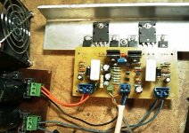
APEX HX11 is tested design
Apex, I was wondering, is there a specific reason or benefit why the input and output connections of your HX11 amp are located in close proximity to another ?
- Home
- Amplifiers
- Solid State
- I'm in search of a class G or H amplifier design