The ZCA has this strange cult following. I think its great. If people are building DIY audio-Yes its great. The ZCA has proved very, very popular but the pressure was applied to come-up with something else. To have a new ZCA or something very similar.
As far as I am concerned a Zero Component Amplifier has one active component. That is ground Zero. Though not an improved ZCA I do offer for your enjoyment the MCA. The Minimum Component Amplifier can have more than one active component but must strive to keep active component count down. In the MCA the PS and bias networks are unchanged but the power Fet (2SK1058) is replaced by a bipolar.
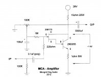
Part of the ZCA/MAC philosophy is to strive to keep component count to a minimum but also to use "off-the-shelf" parts. The bipolar, which is the heart of the MCA is a 2N3055. But the soul of the MCA is a jFet, 2SK170. Keeping the PS and biasing ccts. the same we replace one power Fet with a Darlington pair of jFet and bipolar. This allows me to bias the 2N3055 correctly and give the amp the benefit of a bipolar output. I like the sound.
The transistor runs quiet cool and and so does the jFet. The load Rs get hot. The power is down to 1.2W RMS but the frequency range is <10hz -3db >125kHz. Strictly using the schematic below with a dead quiet 24V PS will produce a lightning fast, simple SS amp with as much punch and slam as 1.2W will incur. The 100hz, 1Khz and 10Khz SQR wave signals into 8.2 ohms (resistive) are excellent particularly the 1Khz SQR wave. This amp out performs the ZCA many times. Still only two caps in the signal path.
Be the first to build a fully fleshed-out MCA.
As far as I am concerned a Zero Component Amplifier has one active component. That is ground Zero. Though not an improved ZCA I do offer for your enjoyment the MCA. The Minimum Component Amplifier can have more than one active component but must strive to keep active component count down. In the MCA the PS and bias networks are unchanged but the power Fet (2SK1058) is replaced by a bipolar.
Part of the ZCA/MAC philosophy is to strive to keep component count to a minimum but also to use "off-the-shelf" parts. The bipolar, which is the heart of the MCA is a 2N3055. But the soul of the MCA is a jFet, 2SK170. Keeping the PS and biasing ccts. the same we replace one power Fet with a Darlington pair of jFet and bipolar. This allows me to bias the 2N3055 correctly and give the amp the benefit of a bipolar output. I like the sound.
The transistor runs quiet cool and and so does the jFet. The load Rs get hot. The power is down to 1.2W RMS but the frequency range is <10hz -3db >125kHz. Strictly using the schematic below with a dead quiet 24V PS will produce a lightning fast, simple SS amp with as much punch and slam as 1.2W will incur. The 100hz, 1Khz and 10Khz SQR wave signals into 8.2 ohms (resistive) are excellent particularly the 1Khz SQR wave. This amp out performs the ZCA many times. Still only two caps in the signal path.
Be the first to build a fully fleshed-out MCA.
Attachments
Last edited:
Hello Mr Houston!
I am interested in building the MCA however I have trouble obtaining the 2sk170 or lsk170 .
Will it be possible for me to substitute another device in its place. ( I have BD 139,BD140,IRF 611,IRF 510 in my parts box).
Along with that, I will like to replace the 15R load resistor with a halogen bulb. Will a 24V 40W bulb suffice?
Thanks in advance.
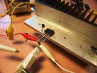
Sorry I can't comment on the use of other driver components or loads. I have only built a rough prototype. I would try yo source the 2SK170 at least. Be aware the Drain and the source are incorrectly marked on the schematic.Hello Mr Houston!
I am interested in building the MCA however I have trouble obtaining the 2sk170 or lsk170 .
Will it be possible for me to substitute another device in its place. ( I have BD 139,BD140,IRF 611,IRF 510 in my parts box).
Along with that, I will like to replace the 15R load resistor with a halogen bulb. Will a 24V 40W bulb suffice?
Thanks in advance.
Thank you.
Do you mean to say that the schematic symbol for the jfet is wrong or the indication is wrong.
Thanks again!
Do you mean to say that the schematic symbol for the jfet is wrong or the indication is wrong.
Thanks again!
Just swap the letter "D" and the "S". The jFET is drawn correctly I just labeled the two legs incorrectly.Thank you.
Do you mean to say that the schematic symbol for the jfet is wrong or the indication is wrong.
Thanks again!
Why not amend the schematic, also emphasizing the 4-way junction at the output node, to avoid confusion since many newbs are attracted to such simple circuits with low parts count and being absolutely clear across language problems helps everyone.
I'm afraid the 2SK170 is also obsolete now but DIYAudio store has made LSK170 available. The problem remains for all the guys who try to use cheap fakes as an unavoidable part of their hobby. Many just don't want to know that their projects won't work properly without genuine parts or even what junk they are actually buying, which is sad, really.
If you experiment with the use of BJTs or at least affordable JFETs with some future, you'll have a lot more happy followers and a better reputation, so keep up the development work.
Last edited:
Sorry this makes me look foolish but the drawing of the schematic and and lettering maybe correct. Proceed with caution. I feel like a dill but I would rather say something than not.Just swap the letter "D" and the "S". The jFET is drawn correctly I just labeled the two legs incorrectly.
Can anyone confirm which is correct?
An N-Channel source-follower has the Drain to +ve rail and Source (output) to -ve, as per your schematic, actually and not (as I just assumed it to be) incorrect.
Interestingly, small signal JFETs are electrically the same either way around, so it's likely you can't tell the difference anyway
Interestingly, small signal JFETs are electrically the same either way around, so it's likely you can't tell the difference anyway
An N-Channel source-follower has the Drain to +ve rail and Source (output) to -ve, as per your schematic, actually and not (as I just assumed it to be) incorrect.
Interestingly, small signal JFETs are electrically the same either way around, so it's likely you can't tell the difference anyway
From the close-up image of the jFET and transistor it looked correct in the schematic. Not sure why I got confused and second guessed myself. There has been none (MCA) built in the wild yet. I'm still waiting to here from some one who will build one. The ZCA is still getting new followers.
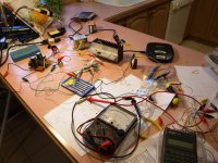
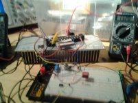
Is that a 1 Meg resistor connected to the wiper of a 100k potentiometer ( what wattage ? )
I see in the photo what appears to be a volume control potentiometer.Can I use one of those?
And the 28v is connected to the collector through the 15 ohm 20 w resistor,correct?
What size choke did you use in the power supply?
I am trying to duplicate your build so I can get identical results.
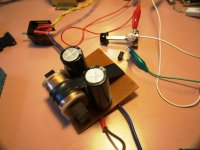
Can you remind me what the iron core inductor and capacitors are doing as shown in the photo? What size inductor is it Mark?
I see in the photo what appears to be a volume control potentiometer.Can I use one of those?
And the 28v is connected to the collector through the 15 ohm 20 w resistor,correct?
What size choke did you use in the power supply?
I am trying to duplicate your build so I can get identical results.
Can you remind me what the iron core inductor and capacitors are doing as shown in the photo? What size inductor is it Mark?
Last edited:
The 1M R is 1/2W. Yes volume pot is OK. Yes to the collector via the resistor. My test choke was 9mh. But a 2H choke is best at 2A.Is that a 1 Meg resistor connected to the wiper of a 100k potentiometer ( what wattage ? )
I see in the photo what appears to be a volume control potentiometer.Can I use one of those?
And the 28v is connected to the collector through the 15 ohm 20 w resistor,correct?
What size choke did you use in the power supply?
I am trying to duplicate your build so I can get identical results.
Can you remind me what the iron core inductor and capacitors are doing as shown in the photo? What size inductor is it Mark?
A great improvement in the ripple rejection, without altering any of the other sound settings:
Try connecting the speaker between + 28 VDC and the end of actual 3300 uF capacitor (reversing the polarity of the capacitor, of course).😉
regards
Try connecting the speaker between + 28 VDC and the end of actual 3300 uF capacitor (reversing the polarity of the capacitor, of course).😉
regards
diegomj1973 would that be connecting the speaker in series with the +28vdc and 3300uF cap?
Yes, like this http://www.diyaudio.com/forums/pass-labs/153832-pass-delite-amp-baf-80.html#post3393890 (only changes the connection of speaker and the 3300 uF capacitor!!!). The rest of the circuit should remain as the original design by Mark.
Last edited:
Hello Mr Houston!
I am interested in building the MCA however I have trouble obtaining the 2sk170 or lsk170 .
Will it be possible for me to substitute another device in its place. ( I have BD 139,BD140,IRF 611,IRF 510 in my parts box).
Along with that, I will like to replace the 15R load resistor with a halogen bulb. Will a 24V 40W bulb suffice?
Thanks in advance.
2sk170 is a JFet, the BD-s are bjt driver transistors, IRF-s are powerMosfets....
Not many substitutes for the sk170, you can try one of the 2n5457-58-59 series, they should work there
A great improvement in the ripple rejection, without altering any of the other sound settings:
Try connecting the speaker between + 28 VDC and the end of actual 3300 uF capacitor (reversing the polarity of the capacitor, of course).😉
regards
Dully noted.
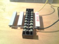
I have decided to try out the MCA, had been intending to build the ZCA but the 2sk1058 I bought on eBay was a fake, I have the big heatsink I bought for the ZCA and I have the TIP3055 the TO-247 version of the 2n3055. I don't have the 2sk170 but will try with dragonweed's suggested substitute, the 2n5458.
Pictures: The big heatsink fin side and flat side with the rogue 2sk1058 attachec
Attachments


A couple of thoughts re the MCA concept:
Using a small Darlington like the MPSA 12 instead of the jfet.
A single IGBT in place of the fet and bjt.
Feel free to ridicule these ideas if they are musically terrible, I'm relatively new to the intricacies of power amp design.
Using a small Darlington like the MPSA 12 instead of the jfet.
A single IGBT in place of the fet and bjt.
Feel free to ridicule these ideas if they are musically terrible, I'm relatively new to the intricacies of power amp design.
MCA MKII???
Inspired by the concept of the minimum component amplifier , I decided to have a go with my own idea, whilst I'm getting parts together to build the ZCA.
I wasn't really expecting anything special, its just a bc549 common emitter amplifier driving a BD139 then a TIP3055 as output transistor in emitter follower loaded with a dirty big 7.6 ohm resistor.
I was blown away, I've never heard such clarity from my speaker ( Morduant Short MS15 ).
Bearing in mind I've never heard a class a amplifier before now, I am totally sold on the idea.
If that's what can be achieved ( without really trying ) I'm besotted like a love struck teenager!
When I've got a final circuit I'll start a thread and post pictures etc, I'm wondering already what might be achievable with better components, the amp was built from stuff I had lying about the workshop.
The best thing about class a is it still sounds OK when distorted.
For now just one photo of my efforts....and one of my home made 7.6 ohm 30 watt resistor! ( it gets bloody hot! )
Attachments
- Home
- Amplifiers
- Solid State
- MCA son of ZCA