You are using an out of date browser. It may not display this or other websites correctly.
You should upgrade or use an alternative browser.
You should upgrade or use an alternative browser.
Filters
Show only:
Subwoofer circuit: Going from speaker level to line level
- By champ04
- Analog Line Level
- 44 Replies
Greetings,
Most modern sub-woofers have both speaker level (high) and line level (low) inputs.
My sub does not have the speaker level inputs. This was not a problem while I was using a pre-amp in my system. But now that I've gone direct from the source, I need a way to include my sub in the system.
I was thinking about creating a circuit that would allow my sub to get it's signal from the main amp.
But before I go any further I am wondering, what's the opinion here on how complicated this might be and degree of difficultly to implement.
All I need is a circuit that takes me from the output level of my amp back to a workable line level that my sub amp can a handle.
Seems simple enough.
Any ideas?
Thanks!!
Long shot - Looking for a pair of Panasonic RF-60s
- Swap Meet
- 0 Replies
Ya know, the Marvin the Martian FM cans from the 60s. Panasonic FM-60, with the loooooong antennas that stick out from the cups. Found a pair on ebay, but they're not quite nice enough. Got scuffs and dents and broken plastic.
Would love to come across a very nice set, preferably with box.
I need a neck workout and I feel that a solid 5 pounds of metal, plastic and silicon on my head at all times may do the trick. 🙄
🙄
Thank you =)
Would love to come across a very nice set, preferably with box.
I need a neck workout and I feel that a solid 5 pounds of metal, plastic and silicon on my head at all times may do the trick.
🙄Thank you =)
Soundstream Reference 300 blowing fuse
Hi Everyone,
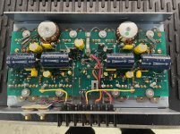
One of my beloved reference 300 amps gave up yesterday just after start up. Here's the details:
- Blows the 30amp fuse only once the remote power is applied, triggering the 'fault' led. Makes me suspect the PS FETS, based on other threads I've read. What else is possible?
- Those 2w 390 ohm resistors are pretty cooked, but they measured OK last time I checked them a couple years back. I don't think they are the problem but I'll probably replace them anyway.
- This amp was second hand to me a long time ago from ebay. It has been worked on before and there is evidence of various driver-side transistors being soldered. And that green resistor nearby certainly isn't original. The job is fairly tidy... can't have been too bad, as the faint marker notes on the board indicated it was fixed by La Belle in 2006 and it has run steady driving my mids ever since. Anyone know him? 😉
I've attached some pics and the rather grainy schematic that's floating around online.
My amp theory is poor, I can *just* read schematics, but I have the tools and am confident working on amps given some direction.
Can anyone give me a steer on how best to troubleshoot / proceed here? What to test, in what sequence and how to do it? While I'm at it, what else should I replace for longevity / performance?
Cheers,
Rob

View attachment soundstream_reference-300_sch.pdf
One of my beloved reference 300 amps gave up yesterday just after start up. Here's the details:
- Blows the 30amp fuse only once the remote power is applied, triggering the 'fault' led. Makes me suspect the PS FETS, based on other threads I've read. What else is possible?
- Those 2w 390 ohm resistors are pretty cooked, but they measured OK last time I checked them a couple years back. I don't think they are the problem but I'll probably replace them anyway.
- This amp was second hand to me a long time ago from ebay. It has been worked on before and there is evidence of various driver-side transistors being soldered. And that green resistor nearby certainly isn't original. The job is fairly tidy... can't have been too bad, as the faint marker notes on the board indicated it was fixed by La Belle in 2006 and it has run steady driving my mids ever since. Anyone know him? 😉
I've attached some pics and the rather grainy schematic that's floating around online.
My amp theory is poor, I can *just* read schematics, but I have the tools and am confident working on amps given some direction.
Can anyone give me a steer on how best to troubleshoot / proceed here? What to test, in what sequence and how to do it? While I'm at it, what else should I replace for longevity / performance?
Cheers,
Rob
View attachment soundstream_reference-300_sch.pdf
Differential vs Balanced DAC outputs
- By SoundBrazil
- Digital Line Level
- 6 Replies
Hi Diyers,
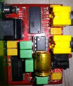
I have an old Korean made DAC based on CS4397-KSZ chip, which has differential voltage outputs, and Im wondering about giving him a tube output stage.
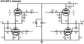
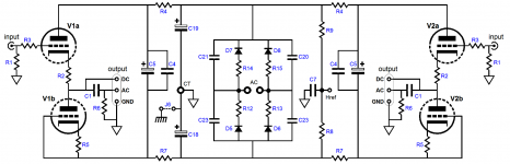
I liked both BCF-2 and ACF-2 circuits from Tubecad.com (for sale at Tube-Based Buffers) , but Im not sure about which one is the more suitable for my DAC, since according to Balanced and Differential , Differential and Balanced outputs are not the same thing.
So, my doubts are:
Are the differential outputs from the CS4397 also balanced?
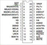
If so, the best option should be the BCF-2 since it has + and - inputs for each channel (dual triode, connecting pins 23 & 24 to V1 and pins 19 & 20 to V2) ?
If ACF-2 is the best option, how should the dac outputs be connected?
All help is welcome!
Tks and rgds
Nilton
I have an old Korean made DAC based on CS4397-KSZ chip, which has differential voltage outputs, and Im wondering about giving him a tube output stage.
I liked both BCF-2 and ACF-2 circuits from Tubecad.com (for sale at Tube-Based Buffers) , but Im not sure about which one is the more suitable for my DAC, since according to Balanced and Differential , Differential and Balanced outputs are not the same thing.
So, my doubts are:
Are the differential outputs from the CS4397 also balanced?
If so, the best option should be the BCF-2 since it has + and - inputs for each channel (dual triode, connecting pins 23 & 24 to V1 and pins 19 & 20 to V2) ?
If ACF-2 is the best option, how should the dac outputs be connected?
All help is welcome!
Tks and rgds
Nilton
Attachments
RSP-1068 Rotel Encoder Volume Control
- By a1095us
- Digital Line Level
- 5 Replies
Hi. I sent a request twice to Rotel for the encoder but they have not replied.
Have any of you replaced this volume control in this Rotel Processor or had any luck finding a generic replacement from Mouser or Digikey ( any supplier)?
This is from the Service manual:
ROTARY ENCODER EC16B243040F (D25) VOLUME
Rotel Part # 056 C-4678A01
Thanks for any help!
Have any of you replaced this volume control in this Rotel Processor or had any luck finding a generic replacement from Mouser or Digikey ( any supplier)?
This is from the Service manual:
ROTARY ENCODER EC16B243040F (D25) VOLUME
Rotel Part # 056 C-4678A01
Thanks for any help!
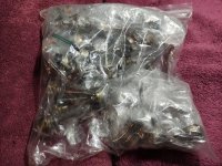
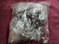
3.5 lbs of Attenuators Potentiometers pots -- NH USA --
$125 or best offer
Make offer in thread, need gone
Make offer in thread, need gone
Attachments
Behringer Powerplay16 SMD cap
- Headphone Systems
- 2 Replies
Hey there,
I use the Behringer P16M headphone mixer system, and one day one of my mixers started to have this problem where you'd only be able to get sound out of the headphones if you'd pan the mix left or right, not in the middle. I opened it up and I found the headphone jack had busted. I ordered a replacement (amprepairparts.com) and swapped it out but that didn't solve the problem. Then I noticed that there are two caps connecting the Tip and the Ring of the headphone jack to ground and one had split in half. These are SMD parts and I can't identify the value, so I tried to measure the remaining one in circuit but no luck so I removed it but destroyed it in the process. I have some 25V 0.1uf SMD caps and they are larger but I don't work with these parts very often. Any ideas for the correct value? C113 and C114 if that helps anyone.
Thanks!
G2 or G3 for volume control
- By Greg Hyatt
- Tubes / Valves
- 13 Replies
As I replace the scratchy pots in my son's Fender amp I have resolved to never use the evil things in the audio path again. Two obvious alternatives are the use of G3 or G2 as suppressors.
Obviously the radio tubes such as the 6D6 provide volume control via G3 specifically for this purpose. A 24V power supply with a pot (out of the audio path) could be applied to the third grid to suppress the gm realizing variable gain from about 2 or 3 to over 100 (with proper load). There must be a good reason not to do this. What is it?
We could also use a Variac, pot, or other means to reduce the voltage to the 2nd grid in a normal pentode or tetrode such as the 6L6 on the output side. Driving the V on G2 down from 400V to 20V will suppress the output by far more than an order of magnitude. Again, I do not observe anyone doing this so there is probably a very good reason.
Please teach me...
Lightning blew my USB interface?
- By 6V6dude
- Digital Line Level
- 3 Replies
Last week a lightning bolt hit a pole in front of our house. It blew up cable modem, router, computer and USB interface that was connected to the PC.
The analog part of the interface still works fine but the USB function does not and won't even show up when connected. Is there anything I should look for when I open it up? Maybe try reset in some way?
On the PC it was the motherboard that got fried, CPU is ok, so I still hope maybe the mixer can be resurrected since rest of it works. Thanks for any advice.
WTB - Scanspeak d2608/913000 Tweeters - North America
- Swap Meet
- 6 Replies
SOLD
Loking to build some Elsinores.
Please let me know if you have a pair to sell and the price.
I'm in Victoria Canada.
Thanks!
Loking to build some Elsinores.
Please let me know if you have a pair to sell and the price.
I'm in Victoria Canada.
Thanks!
Ultrasonic Vinyl Cleaner Giveaway - Free!
I did another giveaway here in June 2017, when Captain Grogg (Greg Shugg) took my three charter subscriptions to "Audio Amateur, Speaker Builder, and AudioXpress" for his students.
At age 74 I got my second COVID vaccination this week an am feeling brave enough for a driveway giveaway. Somehow I managed to lose a longer message moments ago, so I'm not going to embellish too much.
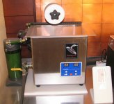
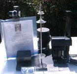
Fremer, AnalogPlanet, reviewed the V8 system a while back:
Ultrasonic V-8 Record Cleaning Machine Cleans 8 Records in 10 Minutes | Analog Planet
On one of the VPI forums it was called 'The Hillbilly cleaner'. It cost $1600 then. The accessory filter system was very lame.
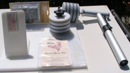
The "Vinyl Stack Ultra Sonic Spin Kit" is brand new unused. With its accessories it cost $330.
My DIY filter and heater mods are untested! Caveat emptor. but you won't be buying it. Time is more important than money to me now. I got a "Degritter".
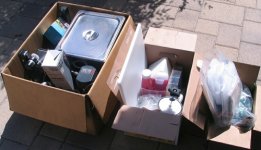
The deal is you come to my home in Long Beach, CA and pickup the stuff. I won't mail anything. If nobody wants it by, say, May 1st then off to the trash pile it is. It would probably be best to contact me via PM.
Oh, an I insist that you take a bottle or two of Hopastat 256 and at least some of the Triton X-100 surficant. There's a couple record crates available to, nicely sanded and varnished.
Hoping someone out 'there' wants the stuff. It was working at last use.
John
B-G RD-75 Dipole Baffle Study
Acoustic Line Source Research
My Offer has been accepted, and hence it is closed. John
At age 74 I got my second COVID vaccination this week an am feeling brave enough for a driveway giveaway. Somehow I managed to lose a longer message moments ago, so I'm not going to embellish too much.
Fremer, AnalogPlanet, reviewed the V8 system a while back:
Ultrasonic V-8 Record Cleaning Machine Cleans 8 Records in 10 Minutes | Analog Planet
On one of the VPI forums it was called 'The Hillbilly cleaner'. It cost $1600 then. The accessory filter system was very lame.
The "Vinyl Stack Ultra Sonic Spin Kit" is brand new unused. With its accessories it cost $330.
My DIY filter and heater mods are untested! Caveat emptor. but you won't be buying it. Time is more important than money to me now. I got a "Degritter".
The deal is you come to my home in Long Beach, CA and pickup the stuff. I won't mail anything. If nobody wants it by, say, May 1st then off to the trash pile it is. It would probably be best to contact me via PM.
Oh, an I insist that you take a bottle or two of Hopastat 256 and at least some of the Triton X-100 surficant. There's a couple record crates available to, nicely sanded and varnished.
Hoping someone out 'there' wants the stuff. It was working at last use.
John
B-G RD-75 Dipole Baffle Study
Acoustic Line Source Research
My Offer has been accepted, and hence it is closed. John
Attachments

Soundstream Reference Class A 6.0
Having trouble figuring out the PS which is using an SG3524 in this amp, which came in with one FET shorted.
First I took out just that one shorted FET, and it seemed to me that none of the others were shorted, so I went to power and it draws excessive current. I pulled the rectifiers and same - excessive draw. Then I took out all the FETs which are IRF3205 (47 ohm gate resistors are good), and I removed Q109 (2n2222A) and Q110 (A1562) which were controlling the side of the FETs which had the one failure (Q106) from the board to test and all the drivers seem to be OK as of now.
So, now the amp takes power but I think there is something going on with the SG3524, but I'm a little rusty. I know that pins 4/5&8 should be close to 0, especially since pin 8 is ground, but instead all three have ~7vDC.
SG3524 (U101) via Fluke 16
1: 4.12
2: 5.32
3: 9.72
4: 6.98
5: 6.98
6: 8.75
7: 7.88
8: 6.98
9: 6.94
10: 6.84
11: 6.04
12: 13.35
13: 13.35
14: 6.06
15: 12.64
16: 10.65
At this point I'm expecting either the SG3524 has failed or something registering on one of the other pins is forcing pins 4&5 to go high. I do notice someone previously changed out all FETs, and all drivers, but SG looks original. It suspect?
I don't have my oscope just yet unfortunately. Darn USPS is taking forever and blaming weather.
Multi-rotor Aircraft Noise Cancellation
- By bradleypnw
- The Lounge
- 4 Replies
You can hear the noise level of a multi-rotor aircraft taking off in the video at the 1:50 mark. A Special Message from CEO and Founder, JoeBen Bevirt - YouTube
The company claims less than 70 decibels on the ground when at 500 feel of altitude. Investor Reid Hoffman claims 65dB at takeoff. https://twitter.com/reidhoffman/status/1372639364782514177?s=20
They use NASA's LEAP-Tech to noise cancel the rotors.
LEAPTech demonstrates electric propulsion technologies – Climate Change: Vital Signs of the Planet
Attachments

6AS7 Class A2
- By bambini
- Tubes / Valves
- 4 Replies
Hello everybody,
I am currently planning an OTL with the 6AS7. I want to drive the tube up to class A2 (VG-1=+10V). In simulation (tube test bench), the distortion increases very sharply at VG-1> 0 V.
Has anyone operated the 6AS7 in this mode outside of the simulation and can confirm that this is the case?
I want to rule out that it is only due to the spice model (...I've already tested different spice models...)
Thank you!
greetings
Bambini
GB: Amplifier Headphone Hum Tester Kit
- By rhthatcher
- Group Buys
- 0 Replies
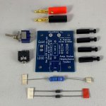
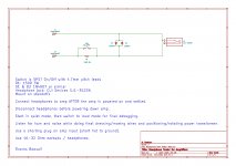
This a DIY kit for use in doing final debugging, addressing ground loops, and doing hum / noise busting in DIY Amplifier builds or repairs. This is very handy when doing final dressing of wiring and rotating a toroidal transformer for the lowest noise floor in your build.
Kit includes PCB, headphone jack, switch, diodes, resistor, banana plugs, and nylon standoff/screws shown.
You need to supply the wire from the PCB to the amplifier and headphones/earbuds.
Refer to the "Headphone Trick" pages in Bonsai's PDF article:
http://hifisonix.com/wordpress/wp-content/uploads/2019/02/Ground-Loops.pdf
$12 + Shipping
14 kits available now, and I can make another GB run based on interest.
PM me or buy directly here:
Amplifier Headphone Hum Tester Kit | Etsy
Attachments

Replacement Tips For Hakko 900M
- By McInRantz
- Equipment & Tools
- 2 Replies
Hey all. I have a Hakko 936 station that takes the 900M tips. Apparently, they discontinued the 900M tips in favor of a new series T18, or something like that.
My questions is has anyone ever used Plato tips on their Hakko units? Or, other "generic" tips for that matter? If so, how do they compare to OEM? Also, does anyone know what the difference is between the old 900M series Hakko tips and the newer T18 series tips? The description under the T18 tips shows that they fit a variety of different Hakko stations, including as replacements for the 900M. I'm just curious as to what is different about them.
Thanks
beveridge 2s and acoustat 4s for sale
- By johnpollak
- Swap Meet
- 2 Replies
I have garaged my speakers for several years, and cannot obviously state their present condition, though they worked fine before garaging. I either need to sell them, or I would consider forwarding the Beveridge speaker to the SF East Bay man who buys and resells them, though I have presently lost his contact information.
The company I funded developed a speaker that was full range and used technology simllar to that in the spectacular Beveridge midrange and highs, and solved the dispersion issue,a lot of the bass volume issue, and had an excellent full range electrostatic performance at 6' tall. The company also developed an amplifier than could properly drive the speaker.
Unfortunately our costs then meant we had to retail it at $ 70,000, which meant that it would have taken an expensive marketing plan to even get it going which I decided not to fund.
We are now working on a more affordable format. The speakers for sale were used as references in developing our speaker. John at 415-902-4707
Diy graphing digital multimeter
- By Mrdrewk
- Everything Else
- 1 Replies
I had this idea to diy a web cam staring at three digital multimeters, taking that info, reading the numbers, and making a real-time running graph. Should be possible yes?
I’m going to start this search by
1 posting idea here to see if any of the community has already done it, or knows where to look
2 starting with Arduino hardware and projects
And finally
3 updating this post with my findings and project.
Any input would be great, thanks!
How to OCR digits real time and use that value in Arduino?
Don’t need arduino, can do OCR from an video stream on the computer using a webcam.
javascript - Detect text from image via Webcam - Stack Overflow
@pinholer neat idea too! Here's a howto I googled. eBay links are dead, but the parts and schematic are probably good. Arduino based multimeter for current voltage indcutance capacitance and resistance
Technics SL-P555 won't turn on
- By TFL95
- Digital Source
- 1 Replies
I think I've just made a massive mistake with my Technics SL-P555.
I finished getting it up and running by installing a new tray belt, all was well, before I went to remove the top cover with the unit still powered on, and it died.
I've checked the fuse, replaced it anyway. No dice.
I've obviously made a major mistake by removing the cover whilst the unit was on.
Can anybody help?
C3m 300b SET question
- By Bassling
- Tubes / Valves
- 90 Replies
Hi,
I have finally decided on the flavour of 300b I want to build, and it is the Loesch Legacy amp with a C3m driver. But I want to start off with a simpler more traditional power supply. I have a couple of questions about this that I would love to understand better, so thought to ask here.
1) In the Legacy amp below, the 300b operating values seem to be set for a 3.5k transformer. Do you agree, and if so what are the implications of replacing the Audion 2.4k transformer with a Lundahl 3.5k/90ma transformer?

2) And if I use the power supply from the 'New Reference Amplifier' on audiodesignguide.com (below), can I just swap out the mains transformer for a 375v one to give a 420v nominal supply? (And what does 'nominal' mean? If I do the current/voltage calculations on the legacy amp, I calculate that the B+ above the driver stage to be 390v not the 420v given)

Thank you sooooooo much for any help, and keep well.
I have finally decided on the flavour of 300b I want to build, and it is the Loesch Legacy amp with a C3m driver. But I want to start off with a simpler more traditional power supply. I have a couple of questions about this that I would love to understand better, so thought to ask here.
1) In the Legacy amp below, the 300b operating values seem to be set for a 3.5k transformer. Do you agree, and if so what are the implications of replacing the Audion 2.4k transformer with a Lundahl 3.5k/90ma transformer?
2) And if I use the power supply from the 'New Reference Amplifier' on audiodesignguide.com (below), can I just swap out the mains transformer for a 375v one to give a 420v nominal supply? (And what does 'nominal' mean? If I do the current/voltage calculations on the legacy amp, I calculate that the B+ above the driver stage to be 390v not the 420v given)
Thank you sooooooo much for any help, and keep well.
Round cutout IEC connector
Hi, I'm looking for a round AC power IEC connector. I kept looking for different makers but they all need a square cutout, I need a round cutout to be able to execute it with a bench drill with a conical drill. Can you direct me to a site where I can find something like that?
A sorry tale of woe and stupidity: NAD C370
- By JamFool
- Solid State
- 201 Replies
Hi,
Background….
I have owned the NAD C370 for about 18 happy years. The only problem I ever had was with the protection circuit.
This I managed to fix by swapping out the capacitors on the protection board and moving the Zener diode to the other side.
The amp continued to work ever since without problems.
Recently I invested in some new studio gear – audio interface, patch bays etc. After reorganizing the room I hooked up the amp to the system and found that only the left speaker had sound.
I checked the signal coming from the audio interface on both channels – no problem there. I checked the signal being sent from the patch bay – no problem there. I swapped the speaker cables on the back of the amp – the sound now came through the right speaker so the speakers are OK and I concluded that the problem must be the right channel on the amp.
I opened up the amp and had a look around. I noticed that one of the four large capacitors (10 000uf) had a little bulge on the top. To check I switched the left and right pairs over… no change so I guess they were OK.
I swapped the left and right pairs of output relays… no change again so I guess these were OK too.
Next I removed and inspected the right power amp board – I found the two large white resistors on each end had cold/loose solder joints, in one case the track had lifted up from the board. A few more solder joints looked suspect so I reflowed them.
Sadly, still no sound from the right channel.
Then an idea came to me – a really stupid idea! I thought I could isolate if the problem was on the power amp board by swapping the left and right boards. I took out both boards and went to connect the molex leads. All of the interconnects were the same apart from one small lead in the middle. The right side had a connection with 3 pins and the left just two.
Right side…..

Left side….

Without thinking I hooked them up so that all the connectors apart from these two were from the same side – so these ones were crossed over – what a stupid thing to do ☹
I powered on the amp and the green lights flashed on for a moment and then nothing – just a bad smell as something had burnt out. I cursed myself and swapped the boards back. Inspected the fuse and found it was blown.
I replaced the fuse and the amp came on – green lights but now there was no sound from either channel. I noticed that when I touched the two pinned cable on the left board that it made a humming sound.
In despair I looked to Finn.no and found someone was selling a C370 quite close by. I bought it and had it back home the same evening.
I hooked it up to my system and was stunned to find that sound was only in the left speaker!! OMG, this meant that there had been nothing wrong with the amp all along!! Arghhh….
Sure enough the real problem had been with the brand new cable from the patch bay to the amp inputs – can’t believe I did not check that. I checked the cable from audio interface to patch bay and the signal from the patch bay output but missed the cable from the patch bay to the amp – double idiot!
I repaired the cable and sound now came from both speakers.
So, I managed to destroy my perfectly good amp and buy a new identical one when all I needed to do was rewire a cable – I didn’t even think to check it as it was brand new. I could cry.
There is my sorry tale of woe. My question is – do you think there is any way to rescue the old amp? What I did to it is so unusually stupid that I will not find similar accounts or fixes online. Do you have any idea how I could start to find out what damage I did?
I would really appreciate any help anyone could offer on this.
Background….
I have owned the NAD C370 for about 18 happy years. The only problem I ever had was with the protection circuit.
This I managed to fix by swapping out the capacitors on the protection board and moving the Zener diode to the other side.
The amp continued to work ever since without problems.
Recently I invested in some new studio gear – audio interface, patch bays etc. After reorganizing the room I hooked up the amp to the system and found that only the left speaker had sound.
I checked the signal coming from the audio interface on both channels – no problem there. I checked the signal being sent from the patch bay – no problem there. I swapped the speaker cables on the back of the amp – the sound now came through the right speaker so the speakers are OK and I concluded that the problem must be the right channel on the amp.
I opened up the amp and had a look around. I noticed that one of the four large capacitors (10 000uf) had a little bulge on the top. To check I switched the left and right pairs over… no change so I guess they were OK.
I swapped the left and right pairs of output relays… no change again so I guess these were OK too.
Next I removed and inspected the right power amp board – I found the two large white resistors on each end had cold/loose solder joints, in one case the track had lifted up from the board. A few more solder joints looked suspect so I reflowed them.
Sadly, still no sound from the right channel.
Then an idea came to me – a really stupid idea! I thought I could isolate if the problem was on the power amp board by swapping the left and right boards. I took out both boards and went to connect the molex leads. All of the interconnects were the same apart from one small lead in the middle. The right side had a connection with 3 pins and the left just two.
Right side…..
Left side….
Without thinking I hooked them up so that all the connectors apart from these two were from the same side – so these ones were crossed over – what a stupid thing to do ☹
I powered on the amp and the green lights flashed on for a moment and then nothing – just a bad smell as something had burnt out. I cursed myself and swapped the boards back. Inspected the fuse and found it was blown.
I replaced the fuse and the amp came on – green lights but now there was no sound from either channel. I noticed that when I touched the two pinned cable on the left board that it made a humming sound.
In despair I looked to Finn.no and found someone was selling a C370 quite close by. I bought it and had it back home the same evening.
I hooked it up to my system and was stunned to find that sound was only in the left speaker!! OMG, this meant that there had been nothing wrong with the amp all along!! Arghhh….
Sure enough the real problem had been with the brand new cable from the patch bay to the amp inputs – can’t believe I did not check that. I checked the cable from audio interface to patch bay and the signal from the patch bay output but missed the cable from the patch bay to the amp – double idiot!
I repaired the cable and sound now came from both speakers.
So, I managed to destroy my perfectly good amp and buy a new identical one when all I needed to do was rewire a cable – I didn’t even think to check it as it was brand new. I could cry.
There is my sorry tale of woe. My question is – do you think there is any way to rescue the old amp? What I did to it is so unusually stupid that I will not find similar accounts or fixes online. Do you have any idea how I could start to find out what damage I did?
I would really appreciate any help anyone could offer on this.
Attachments
bring down the bass hump
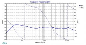
I've been playing around with a 3-way crossover and it's fairly flat above 200 Hz but below that I have 5-6 db of gain @ ~ 60 Hz. I'm using the RS225-8 in a 45l bass reflex. Right now I'm using a 2nd order LR and can't seem to bring it down at all. the phase also looks a bit crazy. I'm a novice so it's not clear what to do next.
Attachments
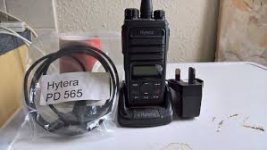
Hytera Digital portable radio model PD565 VHF diagram
- By seditiouss
- Everything Else
- 0 Replies
Hello!
Does anyone have the scheme from Hytera Digital portable radio model PD565 VHF or Hytera - another model / something similar?
It was dropped into the water and doesn't start anymore.
Thanks
Does anyone have the scheme from Hytera Digital portable radio model PD565 VHF or Hytera - another model / something similar?
It was dropped into the water and doesn't start anymore.
Thanks
Attachments
Search for NOS/NEW Tubes
- By Best Hi End
- Tubes / Valves
- 21 Replies
Hi Guys,I need your educated opinion preferably based on pracatical experience-I want to buy quite a few NOS or New which ever sound better and I'm looking for the following tubes ECC88,805A and KT66 or all it's equivalent at an appealing prices and I would be thankful if you could refer me to such sources of sale who are not too greedy in their $ demands for such tubes.
ACA Monoblocks vs. F6 ?
Hello,
I currently am using two ACA's fed by a nuTube B1, driving a pair of Paul Carmody designed Speedster speakers, which I've seen spec'd at 81db sensitivity.
Given the relative inefficiency of the speakers I think things could be improved with more power, but am wondering if the F6 would be sufficiently greater than the two ACAs.
I'm more or less a beginner building amps, so the F5 is probably beyond my capabilities, though I do have local resources who could help.
Appreciate anyone's input (as long as it's balanced ;-)
-- Thing
Modify Australian Monitor AMC+1202P power amp for HiFi use
- Solid State
- 27 Replies
Hi folks
I obtained an Australian Monitor AMC+1202P power amp which is a commercial unit and would like to repurpose it to use as a hifi power amp.
It's a dual mono design, fully discrete with no ICs or opamps anywhere and appears to use good quality parts throughout, so I have hopes it will be a suitable piece to put some effort into.


Here's the schematic:

There are very few caps in it, so I don't think there's much need to upgrade any of them, other than the four 2200uF 63V Jamicon smoothing caps in the power supply stages that appear to have leaked electrolyte and have been discussed here:
Replace leaking caps in Amp PSU stage
I'm wondering if it would be worthwhile to increase the value of the smoothing caps, 2200uF seems a bit small. What would be the benefits of using a greater value to replace them - reduced ripple and increased bass?
The power supply is a bit different to what I'm used to seeing, there is no regulator IC:
The first mod I intend to make after replacing the smoothing caps is to replace the screw terminals for the speaker outputs to proper binding posts as you would find on a domestic hifi amp. I will just disconnect and isolate the 100v and 70v lines - I'll put some heatshrink on the ends of the wires to insulate them and tuck them neatly away. Anyone see any issues with doing this?

I obtained an Australian Monitor AMC+1202P power amp which is a commercial unit and would like to repurpose it to use as a hifi power amp.
It's a dual mono design, fully discrete with no ICs or opamps anywhere and appears to use good quality parts throughout, so I have hopes it will be a suitable piece to put some effort into.
Here's the schematic:
There are very few caps in it, so I don't think there's much need to upgrade any of them, other than the four 2200uF 63V Jamicon smoothing caps in the power supply stages that appear to have leaked electrolyte and have been discussed here:
Replace leaking caps in Amp PSU stage
I'm wondering if it would be worthwhile to increase the value of the smoothing caps, 2200uF seems a bit small. What would be the benefits of using a greater value to replace them - reduced ripple and increased bass?
The power supply is a bit different to what I'm used to seeing, there is no regulator IC:
The first mod I intend to make after replacing the smoothing caps is to replace the screw terminals for the speaker outputs to proper binding posts as you would find on a domestic hifi amp. I will just disconnect and isolate the 100v and 70v lines - I'll put some heatshrink on the ends of the wires to insulate them and tuck them neatly away. Anyone see any issues with doing this?
Attachments

how to mount a heat sink to perfboard ?
- By AudioFanMan
- Construction Tips
- 3 Replies
Im building a power supply from a L78S05, have it on the bread board all scoped up with a nice smooth output. I have two different types of heat sinks for the to-220 and another for the rectifier. From here on out, you will very quickly understand, I am as green as I can be...
The pins on both heat sinks are too big to fit in the perf board. Is drilling the perf board holes out a little more normal practice ?
Do I ground the heat sinks to offer additional shielding? There will be two, and Im not sure if there be any benefit to having them on opposite sides of the small board so that any rf is grounded by the heat sinks (as shields) while in an aluminum chassis. My gut is telling me it should be tied to ground on the secondary's center tap and that's all of the shielding I should need. But I also want to run the mains earth ground to that chassis. I want to make this a quiet and safe as I can, but all of the pieces of everything I have been learning wont quite fit together (yet)..
Wharfedale W2: Power Handling
Hi all,
I have a pair of Wharfedale W2's - an early version with the alnico Super 5's - and I was wondering if an early solid-state amplifier, a Sony TA-1120 (30 watts into 16 ohms), might risk damaging this rare tweeter?
I've googled quite a bit but haven't found the definitive word on this. The manufacturer's catalogue insists on 15 watts max., but there are also indications otherwise, British manufacturers being more conservative about power ratings and so on.
See for instance,
1964 British Wharfedale W2 Speakers - SALE PENDING For Sale - Canuck Audio Mart
I'm wondering if some of the experts on this board might be able to comment? Much appreciated.
Is there an Alternative to MCM 54-580 or Pyle Pro PH65
I would like to build the Zaph Waveguide TMM. Unfortunately I can't seem to find the MCM 54-580 or the Pyle Pro PH65. I've ordered on the sites that show that they have stock only to have the order canceled because they can't fulfill it.
Does anyone know of an alternative that will work in place of the MCM or Pyle part?
Thanks,
MM
Does anyone know of an alternative that will work in place of the MCM or Pyle part?
Thanks,
MM
HELP HELP HELP - AES / EBU ..!
- By Serjio76
- Construction Tips
- 4 Replies
Hello, I need help from knowledgeable people - in the 21st century there was an urgent need to connect an AES / EBU signal (110 ohm - max 7 volts) to an I2S receiver (max 5 volts) ...
100 years almost all manufacturers of CD players and DACs - make such an input ... Can someone give me a good proven schematic diagram of this connection (for example used by companies such as Accuphase, Madrigal, Sony, McIntosh) ... list the necessary details?
100 years almost all manufacturers of CD players and DACs - make such an input ... Can someone give me a good proven schematic diagram of this connection (for example used by companies such as Accuphase, Madrigal, Sony, McIntosh) ... list the necessary details?
Audiocontrol 6xs burnt resistor or two ?
I just bought a used Audiocontrol 6xs crossover. Upon opening it up to see what frequency modules were inside I noticed a burnt resistor next to the remote level control jack. R167 is burnt to a crisp and R148 next to it looks like it got warm as well. I haven’t pulled the board out yet to see where the traces go but I assume it is part of the remote level input. First does anyone happen to know the values of these or at least the burnt one? R148 is a 10k, the other is unknown. Does anyone know if they had problems with the remotes burning resistors on the board or maybe have a clue what might have happened here? Any help would be appreciated. Thank you much. Mike
Attachments

Trying to play my LPs over my WiFi - I missing something
Trying to play my LPs over my WiFi - I'm missing something
Hi, Gang,
Every search I do returns playing WiFi over my system, that's the mirror image of what I want to do.
I'd like to play my LPs (and RtR ) over my Wifi network. I'm not wild about BlueTooth, btw. I'd rather convert my analogue to something that can act as a source over my network. Can this be done, and if so, what hardware do I need?
Thanks,
Frank
Question about dependent windings and hum
- By indaco
- Power Supplies
- 10 Replies
Hi all, I've currently at hand a transformer with three secondaries (all deriving from a single winding) for feeding two independand circuits: one for tube and the other one for S.S. I cannot treat it as it were center-tapped because voltage aren't balanced at zero (0-14-20Vac).
Furthermore, since I want to use a full wave rectifier (and not half-wave) I may have some trouble with resulting hum connecting respective grounds.
I found that with the below schematic, with elevated ground to heater's tube, no more noise comes out. Can anyone explain that or whether is there some error in my circuit? Thanks.
Attachments
Power transformer as Parafeed output?
- By Jeb-D.
- Tubes / Valves
- 60 Replies
Just curious if anyone has tried using a power transformer as a parallel feed output transformer?
threshold
- By tze-hao yen
- Pass Labs
- 1 Replies
hi there i have a sa-4 from stereo exchange long time ago it has a cold one side the other one is hot has been fixed once but recently problem reappear again is there any cue ?
I live in park slop 13 st and 8 ave in the corner
I live in park slop 13 st and 8 ave in the corner
Beginner modern 2.5 way design
This is my first post (Hi all!), but I'm reading this forum for a while and I'm really enjoing your posts guys!
I love good audio. I didn't invested a ton in audio equipment.. my gear for so far are the Monitor Audio RX6 floorstanders, the LS50 wireless speakers and Marantz SR6010. I have an 13" inch subwoofer, but I'm not using that one very often since we have a baby. The ruffle of the subwoofer is hard. That;s great for horror movies or thrillers, but in normal music listening or TV shows it's pretty annoying.
I want to move my LS50 wireless speakers to my desk and get floorstanders again in the livingroom. The constraint is that they need to be placed close to the corners. I can buy new speakers from KEF or any other manufacturer, but I think that I will enjoy the journey to develop my own speakers with higher quality components. I'm a beginner, so I have a lot to learn (and I want to learn)!
What I miss from my LS50 is the size of the soundtage. They sound nice, but they sound as small speakers. Subwoofer integration is very hard to get right. My RX6 do have a muche bigger soundstage, but lesser warmth and refinement.
They design and look of the speakers have to be modern and not that big. (I don't want to place myself in the position to have to chose between my wife or my speakers 😀) I have to place the speakers in the corers (I will post photos of the living room later).
The SBA 761 of Troels look like a good starting point, but I want to use a different tweeter (Bliesma T35B). I have shortlisted my midrange and woofer to two brands/types: Satori MW16 or the Audio Technology C-quenze 18H.
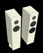
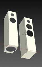
I have to different design ideas now. The speaker on the right, is almost exactly the SBA761 with the 6.5"mid-woofer and 7.5" woofers. The speaker on the left is an idea of mine: Placing a 10" (sub)woofer (for example the Audio Technology 10C77 that Troels use in other designs) in a partial cone shape and keeping the rest of the speaker small. In that case I will get rid of 7.5". The cone shape at the bottom of the left speaker will be bigger that this impression.
I think that I can get 30L volume for the 10c77. In other speakers Troels is saying that this woofer performs very well even in small size volume/cabinets. Will I get a trouble with this design choice? Things like time alignment or the corner placement of the speaker?
Which direction would you advice? Staying within the tried and verified method of the SBA 761 or try my crazy-cone-bottom-firing-bigger-woofer? Any guidance what the effect of the cone shape in the enclosure will be? How to tweak it's size to benefit form this shape?
Maybe not the main topic, but if people tested the Audio technology c-quence line VS the Satori's (Textreme or the older version), please let me know which you prefer and why!
I love good audio. I didn't invested a ton in audio equipment.. my gear for so far are the Monitor Audio RX6 floorstanders, the LS50 wireless speakers and Marantz SR6010. I have an 13" inch subwoofer, but I'm not using that one very often since we have a baby. The ruffle of the subwoofer is hard. That;s great for horror movies or thrillers, but in normal music listening or TV shows it's pretty annoying.
I want to move my LS50 wireless speakers to my desk and get floorstanders again in the livingroom. The constraint is that they need to be placed close to the corners. I can buy new speakers from KEF or any other manufacturer, but I think that I will enjoy the journey to develop my own speakers with higher quality components. I'm a beginner, so I have a lot to learn (and I want to learn)!
What I miss from my LS50 is the size of the soundtage. They sound nice, but they sound as small speakers. Subwoofer integration is very hard to get right. My RX6 do have a muche bigger soundstage, but lesser warmth and refinement.
They design and look of the speakers have to be modern and not that big. (I don't want to place myself in the position to have to chose between my wife or my speakers 😀) I have to place the speakers in the corers (I will post photos of the living room later).
The SBA 761 of Troels look like a good starting point, but I want to use a different tweeter (Bliesma T35B). I have shortlisted my midrange and woofer to two brands/types: Satori MW16 or the Audio Technology C-quenze 18H.
I have to different design ideas now. The speaker on the right, is almost exactly the SBA761 with the 6.5"mid-woofer and 7.5" woofers. The speaker on the left is an idea of mine: Placing a 10" (sub)woofer (for example the Audio Technology 10C77 that Troels use in other designs) in a partial cone shape and keeping the rest of the speaker small. In that case I will get rid of 7.5". The cone shape at the bottom of the left speaker will be bigger that this impression.
I think that I can get 30L volume for the 10c77. In other speakers Troels is saying that this woofer performs very well even in small size volume/cabinets. Will I get a trouble with this design choice? Things like time alignment or the corner placement of the speaker?
Which direction would you advice? Staying within the tried and verified method of the SBA 761 or try my crazy-cone-bottom-firing-bigger-woofer? Any guidance what the effect of the cone shape in the enclosure will be? How to tweak it's size to benefit form this shape?
Maybe not the main topic, but if people tested the Audio technology c-quence line VS the Satori's (Textreme or the older version), please let me know which you prefer and why!
Attachments
FS: 1x Jantzen JA-8008 HMQ New driver
- By Shutdown98
- Swap Meet
- 1 Replies
For Sale
1x Jantzen JA-8008 HMQ
New driver in Original package. Never used.
€175,-
1x Jantzen JA-8008 HMQ
New driver in Original package. Never used.
€175,-
Transformers - potted or not?
- By Giallograle
- Power Supplies
- 8 Replies
I am looking for a pair of toroidal transformers for a preamplifier power supply, and I recall reading @EUVL in the F5X transformers thread suggesting that a open-core transformer would be better-suited to this purpose than an encapsulated one. https://www.diyaudio.com/forums/group-buys/204203-f5x-transformers.html
I've seen this mentioned elsewhere as an unattributed comment, I think because it should have lower capacitance and transmit less mains noise across the windings?
As Patrick is known to be thorough in his testing, has anyone tested this proposition, or have direct experience of the difference between open and encapsulated cores in a power supply?
Diy repair Grundig FineArts V12
- By ChRS
- Solid State
- 4 Replies
Hello enthusiasts,
I read this great forum since 12 years ago, but today I decided to create an user and ask you for help.
I bought an working Grundig FineArts V12 amplifier and I started to give it a new "life" by replacing old electrolytic caps inside. Before I started the work, I measured the power supply voltages and they seamed to be quite right compared to the schematics. The little exception that I had it, is that main power supply is designed to work at 230V ac, but in my area I have constant 240V. I suppose that the manufacturer has considered a +/-10% tolerance for the main supply voltage, so maximum will be 253V.
Anyway, when I started to make the measurements, I observed that on right channel, on output, I had a dc offset of -150mV when tone defeat is On and -80mV when tone defeat if Off. On the other channel the dc offset is ok (+26mV).
I started to replace all elec. caps, I remeasured the dc offset on the right channel, nothing changed. I decided to replaced all the transistors (incl. final trans.), all the diodes and all the resistors with a metal film, same dc offset at the output. All the replaced components were new and bought from a trusted supplier.
I started to dig up even more, to measure transistors voltage between left and right channel and saw that on T405 the collector voltage is 2V higher that T402 collector (on the schematic the voltage difference should be 0.7V). On the good channel the difference is ok. I mention that transistors in the current mirror were replaced with new ones.
Another thing to mention is that T406 (also T306) are quite hot (I measured about 50 degrees C or 122F) and when I start to cool down, dc offset lowers a bit.
At this moment I am stuck and don't know what to do in order to reduce or correct the output of dc offset. For this reason I am asking for your help.
Please find attached the schematic of the mentioned amplifier.
Kind regards,
Chris.
Attachments
Audiophonic I-TDA1387 TCXO DAC Raspberry Pi
- By ernesternest
- Digital Source
- 49 Replies
Good day,
In another DAC thread here on DIYA member Soundcheck mentioned this DAC and qualified it as surprisingly impressive, or so. Even I am a very satisfied owner of a sligthly modded excellent AYADAC with TDA1541 S1 dac and I was currently playing around with IANs newest thingies, I thought I need this dac. Not at least that I consider Soundcheck being a very critical mind.
It helped that this is more a budget dac for the raspberrypi.
As soon it arrived it was plugged into my DCDC converter less Pi and yes, it really surprised me. Even more, when I put the FifoPi board in between.
What a threedimensional soundstage, what an involving sound. I rarely "hear" my speakers and with this source they completly dissapeared. The room expanded far to the rear. The word 'real' came into my mind. I started to understand Abraxelito and his being dedicated to the TDA1387 chip.
Both my other dacs, especially my AYADAC, are excellent dacs and in any case more detailled and have some other preferrable things, still this one is very special in its own way and I would like to reveal more of its potential and this is why I opened this thread.
I would like to share my findings and receive info from members they already went down the road with this dac or its simpler, but otherwise similar siblings that are only to get from Asia.
My plans so far are:
*reading more about Abraxelitos dacs.
*Bringing the curcuit to paper in order to understand this implementation. Has anybody done this?
*I'd like to have it run in synchronous mode instead of ASR. Is removing the VHC574 the only way?
*I'll change the I/V resistor to lower value and a better resistors. First lower and then better. Rhopoint maybe since I am happy user of them in my AYADAC.
*Thinking of an active I/V stage, if this is the outcome from reading Abraxelitos thread.
*Later I want to try Ivans transformers I got for the TDA1541
Maybe something else.
Please, let us keep this thread to mainly the TDA1387 in this application and having some input from Braxis findings.
And, let me mention, I am slow and like listening to music. So the whole process might take some time.
Cheers, Ernst
Peavey CS-400 Series B - Looking for mosaic of drive board #99009030
- By MalVid50
- Instruments and Amps
- 2 Replies
Hello everyone.
Sorry for my English but I am retired, I live in Poland. My grandson helps me write this post. Last year I got an old, damaged and incomplete PEAWEY CS-400 amplifier model: B-Series, 9-78 from 1978 and I want to bring it to full technical efficiency. Two drive board # 99009030 is missing in this amplifier. I need the appearance (photos) of the PCB from the mosaic side to recreate these modules. The module was developed with one IC type TL071 and the documentation that I bought does not include the PCB appearance (photos). I will be very grateful if you can help me solve my problem.
Sorry for my English but I am retired, I live in Poland. My grandson helps me write this post. Last year I got an old, damaged and incomplete PEAWEY CS-400 amplifier model: B-Series, 9-78 from 1978 and I want to bring it to full technical efficiency. Two drive board # 99009030 is missing in this amplifier. I need the appearance (photos) of the PCB from the mosaic side to recreate these modules. The module was developed with one IC type TL071 and the documentation that I bought does not include the PCB appearance (photos). I will be very grateful if you can help me solve my problem.
Odd noise musical fidelity LXS LPS
- By poundy
- Analog Line Level
- 11 Replies
I have an odd noise coming from the right channel when on MC setting.Its a light thump,thump,thump then it goes away for about 4 or 5 seconds then comes back, then goes away etc etc.
I wondered if it was the amp as im running it through one of the aux/video channels, but i tried it on 2 other amps and it does the same thing, so it is the LXS or in fact the turntable thats causing it.
i am using an audio technica AT LP-120XUSB turntable with a denon DL-103r MC cartridge.
anyone have any idea what it could be as its only on one channel.??
many thanks, paul
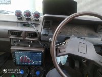
Android player height location
Hi ... Recently installed an android player for my recently bought old car ... The original location for the head unit was a double din located just a little higher than the gear shifter lever and just below the air conditioning controller ... I have considered to relocate the android player to where the location of the external gauge and shift the gauge to the location of the current head unit ... I think it might be a driving danger hazard because the current location is too low so if i relocate it to dashboard location will it be safer? Thanks
Attachments
FS: stereo power output modules EL34 for AMC CVT 3030
For sale two (stereo) power output modules EL34 for AMC CVT 3030.
The tubes are Siemens and in very good condition.
The price is 250 Euro (shipping to EU included). I cannot ship outside EU.
For details, please send me PM.

The tubes are Siemens and in very good condition.
The price is 250 Euro (shipping to EU included). I cannot ship outside EU.
For details, please send me PM.
DIY amplifier here in the forum
- By diyralf
- Solid State
- 11 Replies
Is there a diy amplifier here in the forum that has good verified measured values.
What is it?
- By mdpaudio
- Tubes / Valves
- 10 Replies
What is this Russian tube? Tia

And what is it good for?
And what is it good for?
Loudspeakers, no sound from left Midrange?
Hi All.
Helping a friend sort out some issues with his Technics SB-E100 Loudspeakers.
He's getting no sound from the left Midrange Driver.
The Technics is quite a fiddly build.
It looks like the crossover board is sandwhiched between a circuit board and a faceplate and soldered together.
Quite involved getting it apart.
I've been able to isolate the driver.
I'm thinking it's either:
Faulty driver.
Faulty reset arrangement.
Faulty wiring or
Faulty midrange tone control.
The manual indicates a Breaker value of 1.6A.
There's are reset buttons for the tweeter and mid so maybe there's some electronic devices, maybe thermisters involved??
Was hoping for some directions on how to identify where the problem is coming from.
Cheers
Cliff
Attachments

Audio Research REF 5 Clone Boards
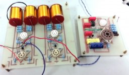
Once Upon a time I cloned an Audio Research ref 5 preamp. We sort of. As a design experiment I duplicated the exact circuit but separated the audio section and power supply section into 2 boards and skipped the Digital volume control section. I used Genuine ARC parts except for the Tube sockets(I could not find an EagleCAD part for the Belton sockets) . Even the Special Moncrief output caps are Genuine ARC parts!
It was a fun experiment and it does work. just never got around to doing anything with it.
You will need to supply your own transformer, Rectifier, PSU Cap bank, 6H30's(5x) and a 6550 for the regulator circuit. as well as chassis, volume control, input's etc...but would also work as a buffer for a DAC etc.
Time to let some projects go.
Asking $100 plus shipping. The Output caps alone were over $50each new so! great bargain!
Attachments
Vintage Transformer Audio Development Co TF1AO2LA 335v 365v .5amp Tube A8691 AMP
$99 shipped USA or best offer
Attachments

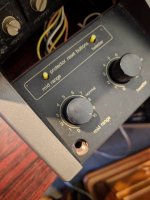
Trimmer on Micromega Solo H
- By atreio52
- Digital Source
- 8 Replies
HI, it lacking schematic, before I make mistakes and intending to change opamp, I'm trying to find out which is the function of the four trimmer in the main board of the MICROMEGA SOLO H. Two regulate the output offset (but which: those closer to the output connectors or those closer to the LF356N?). And the other two?
Can anyone help me? Many thank's
Can anyone help me? Many thank's
remote control freaks
- By davidr3032
- Solid State
- 12 Replies
Hi I have 3 yamaha amps as part of a surround sound setup. When I adjust the volume with one remote, it changes the volume on all 3 amps. I've tried half a dozen yamaha remotes and they all do this. I need to be able to control the volume of each amp individually. Is there a solution? Maybe some sort of DIY motorised volume controller or a simpler fix?
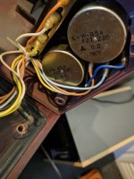
Left and Right Channel volume difference
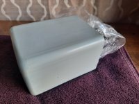
I have some old 2.1 computer speakers that I have been using to listen to recorded meetings/podcasts etc.
The two seemingly 8-10W speakers draw power from the subwoofer. Two cables.
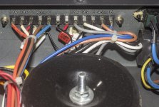
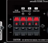
The back of the subwoofer has the left and right ...push-naked-cables-in sort of connectors. See image
Except...Mine has only 4. 2 for each channel.
The left channel works fine. But the right channel audio is low. So I adjust my output from PC to 64:36 ratio. (64 to the low right channel to give it a boost to equalize the volume)
And if I keep the volume on my pc below..say 30-35... eventually the left channel will just go quiet. or keep going in and out.
I don't touch the volume pot on the subwoofer much. I do volume control from pc.
I have changed the 3.5m aux cable that connects from PC 3.5mm to subwoofer 3.5mm input. Didn't help.
Can someone list some places I should be looking? And how to determine which part might be causing this?
I can open up the subwoofer, I can solder etc.
Thank you
The two seemingly 8-10W speakers draw power from the subwoofer. Two cables.
The back of the subwoofer has the left and right ...push-naked-cables-in sort of connectors. See image
Except...Mine has only 4. 2 for each channel.
The left channel works fine. But the right channel audio is low. So I adjust my output from PC to 64:36 ratio. (64 to the low right channel to give it a boost to equalize the volume)
And if I keep the volume on my pc below..say 30-35... eventually the left channel will just go quiet. or keep going in and out.
I don't touch the volume pot on the subwoofer much. I do volume control from pc.
I have changed the 3.5m aux cable that connects from PC 3.5mm to subwoofer 3.5mm input. Didn't help.
Can someone list some places I should be looking? And how to determine which part might be causing this?
I can open up the subwoofer, I can solder etc.
Thank you
Attachments
E-MU 0204 Driver for Windows
- By skidave
- Software Tools
- 5 Replies
Does anyone have the installation CD for the E-MU 0204? I picked one up, but it did not come with the installation CD. There is no Windows driver on the website. I'm just running XP, and I could not find a driver via a Google search.
Anyone able to copy to drop box or burn me a copy?
Thanks,
Dave
Anyone able to copy to drop box or burn me a copy?
Thanks,
Dave
unique mic design 2
- By hifijohn
- Everything Else
- 0 Replies
another pone of my unique mic designs, the element is a3" driver from a cheap boombox, Im using a 6.3-volt transformer wired backwards to stepup the output.
Imgur: The magic of the Internet
Imgur: The magic of the Internet
FS : 2x 1200VA Toroidy Audio Supreme Ecapsulated transformers
- By pinnocchio
- Swap Meet
- 4 Replies
Hi For sale I have the following two toroid transformers. I would prefer selling in pair.
New, never used
Brand : Toroidy
Model : Audio Supreme TS1200VA
Input primary : 1x 119Vac
Output secondary : 4x 17.5Vac (can be connected in parallel or series)
Shield wire : yes
Lead length : 40cm wires
dimension : 210mm x 90mm
weight : ~11.5Kg
Price paid was SOLD Euros /each + SOLD Euros shipping
I want to sell them SOLD$USD /each + shipping. Reasonable offers will be considered but no low balllers.


Thanks
Do
New, never used
Brand : Toroidy
Model : Audio Supreme TS1200VA
Input primary : 1x 119Vac
Output secondary : 4x 17.5Vac (can be connected in parallel or series)
Shield wire : yes
Lead length : 40cm wires
dimension : 210mm x 90mm
weight : ~11.5Kg
Price paid was SOLD Euros /each + SOLD Euros shipping
I want to sell them SOLD$USD /each + shipping. Reasonable offers will be considered but no low balllers.
Thanks
Do
Help identifying speakers
- By jwags81818
- Multi-Way
- 4 Replies
I bought this pair of multiway speakers yesterday. They are in a transmission line cabinet that weighs a metric ton. this is what I know from the person I bought them from.
They were designed by Steven Geist for Hawthorne Audio in Portland Oregon in the 90's. Evidently they were a popular offering. Was told they were the precursor to the Linnaeum speakers.
I was wondering what driver is in these. See pics.
They actually sound amazing. HUGE soundstage. Fairly efficient too as my 7 watt 300B SET drives them just fine.
I paid $200 for them and they appear to be worth every bit of it and then some. Can't get over how much the enclosures weigh.
Do these have a name??
Attachments
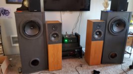
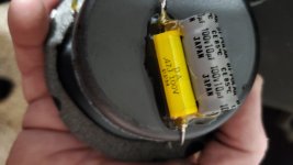
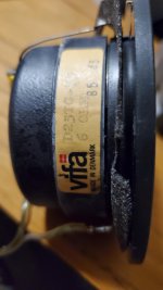
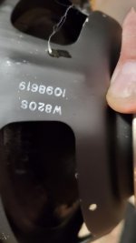
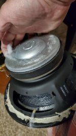
plz check my ported box math.........
- By norman bates
- Full Range
- 7 Replies
3.89ft3 (slightly bigger than standard 4th for 8" full range driver)
tune to 31hz
I get 3" port 2.56" long
I get 2" port .61" long
is this right ?
tune to 31hz
I get 3" port 2.56" long
I get 2" port .61" long
is this right ?
FS Svetlana SV572-10 NIB
Hello,
I have located another box of these interesting power triodes in my extensive hoard and I an offering them up for sale.
These are NIB and I am asking $50 USD per tube plus shipping charges.
Thanks for looking today

Such nice and durable construction yes?

Thanks for looking
I have located another box of these interesting power triodes in my extensive hoard and I an offering them up for sale.
These are NIB and I am asking $50 USD per tube plus shipping charges.
Thanks for looking today
Such nice and durable construction yes?
Thanks for looking
Multiple amps to same driver?
- By NBPK402
- Solid State
- 0 Replies
I have a ACA mono and a Icepower mono amp and would like to run thenACA amp only when I listen critically. I would like to do this for my front 2 or 3 channels i can turn on and off the amps remotely, but I am not sure how to wire it. I thoughtnabout using a xlr "Y" to go from my crossover to each of the 2 amps, but was told that will not work due to impedance. I was told that maybe I could install a 2nd pair of speaker wire jacks on the Icepower amp and plug the speaker wires from the ACA i to the icepower amp case and use a relay to select which speaker wires go tonthe speaker out jacks on the Icepower. Is there a simple circuit or a board Incould purchase that could do this with little impact on the sound?
BT chips/modules that support True Wireless Stereo APT-X
- Digital Line Level
- 2 Replies
Hi,
CSR64215 supports True Wireless Stereo. True Wireless Stereo enables one to embed the CSR modules in each of the left and right speakers and stream BT audio from laptop/mobile while BT maintain tight audio timing in both the speakers. Easy way to make wireless active speakers. However, there are not many DIY friendly modules of CSR 64215 available.
Are there any such non CSR modules available for DIYers to use?
Thanks and Regards,
WonderfulAudio
Enclosure design
- Construction Tips
- 7 Replies
Hello everyone,
I have a 5.25inch, 25w subwoofer driver. I wanted to design an ported wooden enclosure for this driver. Can anyone give me the best dimensions of the enclosure.
I tried to get the dimensions from the online tools. But it was very difficult for ....me as it was asking to enter too many inputs.
I'm still a beginner in this Audio related stuffs. So please help me guys.
Possible Jensen Transformer Damage
I'm building my first solid state amp and I decided to go with the F6 based on my use case and the fact that the M2 boards were backordered when I made my purchase. Once I got to soldering the transformers on, I noticed that one of the transformers had some of the laminations that were splayed apart. It's a super minor condition on 3 of the corners, only affecting the top 2 or 3 plies.
Am I OK just running these as is? My other idea was super glue and a zip tie to stick it back down. I'm probably just being overly nervous due to this being my first real DIY build.
Am I OK just running these as is? My other idea was super glue and a zip tie to stick it back down. I'm probably just being overly nervous due to this being my first real DIY build.
Attachments
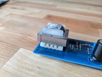
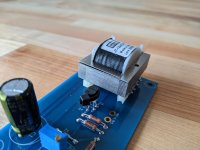
Old steel to-3 to ansistors vs new semiconductor pluses and minuses
- Pass Labs
- 6 Replies
So I encounter various equipment. Often i see steel transistors (to-3 I believe) on
Old pioneers. Encapsulated in flat steel cylinder.
And new black or green colored semiconductor transistors. Rectangular shape
What are benefits of each type of output transistor. Ive heard to-3 steel type are unreliable and can leak .. easily stressed.
It's one major reason i am always selling or avoiding old amps with those to-3 types of transistors
And would prefer nakamichi pa-7 over threshold s300 or whichever one was copied by nakamichi. I think s300 used old steel output transistors
Tube aviation test equipment
OK everyone, this is a bit different. I bought this in the 1970s from a downtown Toronto electronics surplus shop where it was on consignment. I spoke by phone with the owner who described it as an amplifier used to run AC motors at various speeds to shake the wings on CF-100 fighters for stress testing. The design is consistent with his description. Built in Canada. Lots of Hammond transformers/inductors. It has 4 - 807 output tubes.
I used it as an audio amplifier to drive a subwoofer.
It is very heavy and local pick-up is preferred.
Truly a piece of Canadian aviation history! For sale to a good home for display or parts...
$50 CAD No shipping available unless you are crazy enough to pay for it.
I used it as an audio amplifier to drive a subwoofer.
It is very heavy and local pick-up is preferred.
Truly a piece of Canadian aviation history! For sale to a good home for display or parts...
$50 CAD No shipping available unless you are crazy enough to pay for it.
Attachments
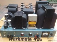

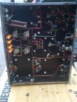

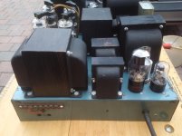
Suggestions on companies for help on floor standing speaker cab design, etc
- Multi-Way
- 2 Replies
Looking for recommendations on a provider who can properly & well design a 3 or more speaker, floor standing speaker cab for good to modestly decent price, and provides a solid plan, steps, details, etc for building it not just a CAD file or whatever.
I already have a pair of Eton 19SD-1 silk dome Tweeters & a pair of Eton 4-512/C8/25 4" paper cone Midranges. I'd need provider that would also assist on selecting 1 or maybe 2 Bass/Subsonic Bass Woofer and maybe Mid Bass Woofer in conjunction with cab design with that/those woofers and the Etons.
I'll have enough room for cabs that are 12.5-18" Width, 36-45" Height preferably 38-42" Height range, Depth I have up to 20" maybe 21" total space of Depth, but don't know how Deep cabs can be nor how far from back wall cabs would need to be.
I'm not looking for any over complicated, high labor intensive & skill design requiring CNC machine, steam shaping wood, etc nor litany of different angled & shaped pieces that must be carefully fit together, etc.
A modern, fundamentally well designed with the select, most beneficial & key to sonic performance design & aspects. Starting with Bass Woofer(s) selection (12-15" Woofer/Subwoofer, possibly 6-8" Mid Bass Woofer) and designing that section of cab (volume, if sealed, passive radiators, or ported & specific details & tuning on them, internal cab shape, bracing, damping fill amount & type) with isolated internal chamber from Mid & Tweeter. Similarly for Tweeter & Midrange. Front baffle design & contours along with the front Left & Right angled corners from front baffle to side panels, side panel shape/design/contours (rounder, V, K shape, etc) and rear panel shape/angles.
Only 1 potential custom/semi custom aspect I'd want if viable. Since Tweeter & Mid don't require much cubic feet of volume, is use portion of that space for a large sealed & isolated from all speakers Xover mounting compartment with rear access only cover, binding posts would be mounted to the cover. Haven't ironed out best method for maintaining seals while running wires from Xover through wood to run to speaker connections yet.
Suggestions on a company/provider who could help & be a good match for this?
A 230v-transformer used as 115v input, the output power is cut down to 1/2 or 1/4?
- By abc135
- Power Supplies
- 4 Replies
Hi,
I got a spare toroidal transformer, input: 230v, output: 48v, 100va. My little project is a 24v DC preamp, so I can use this spare transformer as the power transformer for 115v input, right?
A friend of mine advise me not, because the max output power is now 25va instead of 100va, is it right?
I got a spare toroidal transformer, input: 230v, output: 48v, 100va. My little project is a 24v DC preamp, so I can use this spare transformer as the power transformer for 115v input, right?
A friend of mine advise me not, because the max output power is now 25va instead of 100va, is it right?
5.1 amplifier
I would like to build an amplifier, around 25w per channel, I'm gonna use an asus xonar as pre amp, something easy to do with good sound quality. i saw a lot of lm3886 but I think is too strong for this kind of project. does anyone have another suggestion? thanks.🙂🙂
experimenting with muli coil drivers - damping issues?
- By garethj
- Subwoofers
- 2 Replies
Hello!
I'm looking into a driver with multiple concentric rings of voice coils in a field coil arrangement.
As you get into multiple layers, do issues come up with the frequencies driving the coils starting to go out of time and dampen each other?
I would think it would be something that would need to be tested, as the closest thing that I can think of off the top of my head is dual coil woofers, etc. like the ones you see in the old infinity q series
2.1 amplifier strategy for small desktop
Hi guys,
I'm building a small PC desktop system with 2in Peerless ne65w fullrange and a Dayton TCP115 as sub or better as bass...
Will be listened at moderate volume no more than 1m away so the power requirements are pretty low.
The Winisd models show that power handling can get to maximum 15w if cut at 150/200Hz uncut 6-7w.
I'm building a separate amp case because I like to have the dials at hand under the screen.
The question is:
Should I go 2.1 prebuilt and mod the board to modify/add HPF etc or should I go for 2/3 split amps, put a capacitor filter to the inputs and additional modules?
How would you do it? what amplifier board/s and modules would you use? (Aliexpress and co.) Budget about 20£/30$ plus mods.
Summary of reqirements:
>15w/channel (Mains)
>30w Sub
HPF 150hz for mains
Freq and Vol subwoofer
Main volume
Bluetooth
Bass and treb tuning pots would be a plus, but not necessary.
I don't mind tinker with the boards until I get some guidance or reference material (actually that's the whole objective of the project), can solder, measure etc with no problem, but i'm far from an EE.
No readymade solutions or DSPs please...where's the fun!?!
Thenks in advance for the help!
Measuring/Scoping the Output of a Class D Amp
Most Class D amps use bridging of some sort to obtain higher power. This means that you cannot connect an oscilloscope directly to the output as this woulkd connect one side of the amp to earth. Now most amplifier swill happily drive a transformer to step up the voltage to 100V for PA aplications so can anyone see a problem in using the windings of a transformer between an amp and a scope?
Will this driver in the Tapped Horn configuration?
- By StabMe
- Subwoofers
- 53 Replies
Hey!
So i have this Kicker L7 12" subwoofer laying around and i thought i'd use it in a TH fashion. So i took the SPUD 'leaked' drawing and adapted them to my application by basically making the box wider and accommodating the placement of the driver.
Here is how it looks like in the Sketchup:
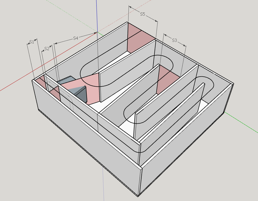
Here is the Hornresp input:

Power response with no filters or EQ:

Filters and EQ applied:

GD graph:

Phase:

When looking at the power response with EQ and filters, seems like this driver can be very loud in this configuration. But when looking at GD and Phase, is there any hope that this sub will not sound like a lot of mud?
Here is a comparison of the same driver in a 90 liter vented box:


P.S. I asked a few related questions in the huge hornresp thread and then decided to start a new one in order to not clutter that thread.
So i have this Kicker L7 12" subwoofer laying around and i thought i'd use it in a TH fashion. So i took the SPUD 'leaked' drawing and adapted them to my application by basically making the box wider and accommodating the placement of the driver.
Here is how it looks like in the Sketchup:
Here is the Hornresp input:
Power response with no filters or EQ:
Filters and EQ applied:
GD graph:
Phase:
When looking at the power response with EQ and filters, seems like this driver can be very loud in this configuration. But when looking at GD and Phase, is there any hope that this sub will not sound like a lot of mud?
Here is a comparison of the same driver in a 90 liter vented box:
P.S. I asked a few related questions in the huge hornresp thread and then decided to start a new one in order to not clutter that thread.
Attachments


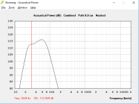
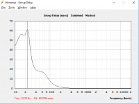
EAR Yoshino V20 Amplifier
- By poynton
- Tubes / Valves
- 25 Replies
Hi.
Has anyone a circuit diagram of this amplifier?
Or a similar one using multiple small triodes?
Thanks
Andy
Has anyone a circuit diagram of this amplifier?
Or a similar one using multiple small triodes?
Thanks
Andy
Schematic for TDA7293 clip detector?
Hi everyone
I want to put clip detector on my TDA 7293 amps and don't understand how. Tried to find answer on forum and google it but failed.
Can someone put a simple picture or explain how to make clip detector for that chip?
I want to put clip detector on my TDA 7293 amps and don't understand how. Tried to find answer on forum and google it but failed.
Can someone put a simple picture or explain how to make clip detector for that chip?
Anyone familiar with these caps?
- Tubes / Valves
- 55 Replies
These are 275VAC (600VDC+). Polypropylene film caps
Wondering if anyone has an opinion of them.
Dirt cheap from China on ebay, seller is robotmaker2015
Intended use would be as coupling caps.
Wondering if anyone has an opinion of them.
Dirt cheap from China on ebay, seller is robotmaker2015
Intended use would be as coupling caps.
Attachments

Sensitivity Measurement
I am trying to determine the target sensitivity of speakers I want to build for some SE amps I am also building. So first I want to benchmark my current speakers to see how much more output I need. I have REW and UMC-1 mic. Did I do this right?
Placed mic 1m away from center of set of speaker drivers.
Played a 1khz tone with a measured amplitude at the amp output of 2.8V RMS.
Use REW SPL measurement to measure SPL, used both A and Z weighting (no difference)
Reading was 82db.
Speakers were in room.
Placed mic 1m away from center of set of speaker drivers.
Played a 1khz tone with a measured amplitude at the amp output of 2.8V RMS.
Use REW SPL measurement to measure SPL, used both A and Z weighting (no difference)
Reading was 82db.
Speakers were in room.
Hair brain direct coupled choke loaded driver stage on a large negative rail.
- Tubes / Valves
- 20 Replies
I’ve had this one in my mind for a while and I finally did get a version working
The idea is to directly couple to a triode strapped pair of GU-50s in a push pull output stage.
It’s tricky because GU-50s are quite low gain in triode mode and need almost 200v p-p. This means nearly -100v on the grids.
So the driver needs to have the plates at -95v or so and be able to swing 200v p-p. No small task.
Also the plate V needs to be individually adjustable so I can bias up the GU-50s. This is why I decided to use choke loaded stages on current sources.
I was originally going to use a pair of 6v6 but recent experiments with the 6E5P made my want to try those.
This circuit is functional as drawn but I think I will be adding local FB at the driver and a input gain stage will replace the input transformer.
What do you think?
Attachments
-
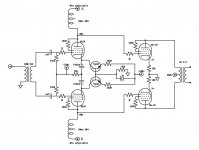 AB72D525-E486-490E-9AE4-712F7A96D140.jpeg169 KB · Views: 382
 -
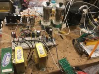 8C406E4B-43E6-41D1-B68E-5AB737C9AFBA.jpg998.3 KB · Views: 383
 -
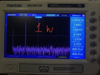 F69BB971-0EF0-44C8-806F-B2F6E7CFBEE6.jpeg631.9 KB · Views: 317
 -
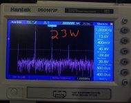 576FB995-36C8-471E-AAB5-E1670DCB8FAA.jpeg640.8 KB · Views: 310
 -
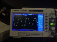 C41BB726-5466-4C38-BEF5-CFE695856673.jpg602.7 KB · Views: 329
Load more
Projects by fanatics, for fanatics
Get answers and advice for everyone wanting to learn the art of audio.
Join the Community
507,807
Members
7,889,176
Messages