Hi Everyone,
One of my beloved reference 300 amps gave up yesterday just after start up. Here's the details:
- Blows the 30amp fuse only once the remote power is applied, triggering the 'fault' led. Makes me suspect the PS FETS, based on other threads I've read. What else is possible?
- Those 2w 390 ohm resistors are pretty cooked, but they measured OK last time I checked them a couple years back. I don't think they are the problem but I'll probably replace them anyway.
- This amp was second hand to me a long time ago from ebay. It has been worked on before and there is evidence of various driver-side transistors being soldered. And that green resistor nearby certainly isn't original. The job is fairly tidy... can't have been too bad, as the faint marker notes on the board indicated it was fixed by La Belle in 2006 and it has run steady driving my mids ever since. Anyone know him? 😉
I've attached some pics and the rather grainy schematic that's floating around online.
My amp theory is poor, I can *just* read schematics, but I have the tools and am confident working on amps given some direction.
Can anyone give me a steer on how best to troubleshoot / proceed here? What to test, in what sequence and how to do it? While I'm at it, what else should I replace for longevity / performance?
Cheers,
Rob
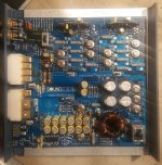
View attachment soundstream_reference-300_sch.pdf
One of my beloved reference 300 amps gave up yesterday just after start up. Here's the details:
- Blows the 30amp fuse only once the remote power is applied, triggering the 'fault' led. Makes me suspect the PS FETS, based on other threads I've read. What else is possible?
- Those 2w 390 ohm resistors are pretty cooked, but they measured OK last time I checked them a couple years back. I don't think they are the problem but I'll probably replace them anyway.
- This amp was second hand to me a long time ago from ebay. It has been worked on before and there is evidence of various driver-side transistors being soldered. And that green resistor nearby certainly isn't original. The job is fairly tidy... can't have been too bad, as the faint marker notes on the board indicated it was fixed by La Belle in 2006 and it has run steady driving my mids ever since. Anyone know him? 😉
I've attached some pics and the rather grainy schematic that's floating around online.
My amp theory is poor, I can *just* read schematics, but I have the tools and am confident working on amps given some direction.
Can anyone give me a steer on how best to troubleshoot / proceed here? What to test, in what sequence and how to do it? While I'm at it, what else should I replace for longevity / performance?
Cheers,
Rob

View attachment soundstream_reference-300_sch.pdf
If it only blows the fuse after remote is applied, the most likely culprits are shorted rectifiers, shorted transformer or shorted output transistors.
I don't know what you know so ask questions and we'll fill in the blanks.
It's common for the regulator resistors to run hot and become discolored.
I don't know what you know so ask questions and we'll fill in the blanks.
It's common for the regulator resistors to run hot and become discolored.
Perry, this rev board looks like it could have been birthed as a Class A 3.0. What does it take to convert? Vr202/302, and a bunch of diodes? Anything else?
I don't know. For the most part, I will not do mods that don't relate to reliability.
This is for another thread. If you want to see if someone else can help, start a new thread.
This is for another thread. If you want to see if someone else can help, start a new thread.
Fingers crossed it's not the transformer.
So my plan is to test rectifiers then fets.
What should my approach be to the rectifiers?
Thanks for the help, of course.
So my plan is to test rectifiers then fets.
What should my approach be to the rectifiers?
Thanks for the help, of course.
Last edited:
In my experience the stock rectifiers are prone to give up very easily, and since they are NLA you'd have to figure something out for a replacement. The fact that they're sandwiched between the board and heatsink doesn't make that very easy. Also those burned resistors look like they may be part of an output zobel network, which makes me think possible oscillations?
Last edited:
The transformers typically have intermittent shorts that can easily be fixed by inserting an insulator.
I don't understand the question about the rectifiers.
I don't understand the question about the rectifiers.
I have some pics of the underside of the board.
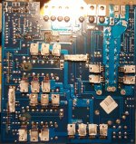
Note how cooked the lower solder points are on those two diodes next to the 390 ohm 2w resistors are. The top side soldering doesn't look so bad.
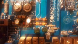
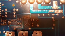
Here's a pic of the rectifiers. D3,4,5,6 on the schematic. They are GI FED16BT 9416.
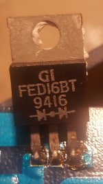
View attachment datasheet FED16BT.pdf
I've used the diode test function on my MM, from one outer leg to the other. One polarity it goes off scale. the other polarity it shows 0.386v. This is the case for all four pieces in-circuit. Am I right in assuming that the rectifiers are OK?
Rob

Note how cooked the lower solder points are on those two diodes next to the 390 ohm 2w resistors are. The top side soldering doesn't look so bad.


Here's a pic of the rectifiers. D3,4,5,6 on the schematic. They are GI FED16BT 9416.

View attachment datasheet FED16BT.pdf
I've used the diode test function on my MM, from one outer leg to the other. One polarity it goes off scale. the other polarity it shows 0.386v. This is the case for all four pieces in-circuit. Am I right in assuming that the rectifiers are OK?
Rob
Last edited:
Now the output transistors. In the schematic they are listed as RFP50N05. However, the writing on all four cases is really faint so I can't take a pic. They are labeled MTP50N05E W 412. So, pretty similar right?
View attachment datasheet MP50N05E NATLD032-2-3.pdf
View attachment datasheet RFP50N05.pdf
I'm assuming I have to test these out of circuit... need to do some reading on the web.
I have a feeling my problems are stemming from those poor solder joints around the 2W resistors and nearby diodes. I'm sure last time I tested those resistors I had to pull them out of circuit, but they read 390 in-circuit just now. What normally happens when these bad boys go burn open?
The rectifiers seem to be OK but you'd check legs 1-2 both polarities, then 2-3, both polarities.
The following is a possible replacement for anyone who needs doublers:
Soundstream Reference 405 (NON S/SX)
One option for the regulator diodes is to mount them on the bottom side of the board (slightly off of the board), then use 4mm thermal gap pad and heatsink compound to make them run cooler.
For the resistors, mount them so that they stand about 1/2" off of the board. This will reduce the heat applied to the board.
here's a better example of a MP50N05E datasheet...
View attachment datasheet MP50N05E MOTOD144-3-550.pdf
I tired to do some tests in-circuit. I thought things behaved strangely. Do I just have to pull them out?
In the meantime I've re-flowed the solder around the 2W 390 Ohm resistors and those nearby diodes. It looks like the diodes have been getting really hot at some point.
The rectifiers seem to be OK but you'd check legs 1-2 both polarities, then 2-3, both polarities.
Thanks Perry, I've double checked those rectifiers.
With DMM on diode setting, in-circuit for all rectifiers:
1-2 one polarity = off scale
1-2 other polarity = off scale
2-3 one polarity = off scale
2-3 other polarity = 0.386v
1-3 one polarity = off scale
1-3 other polarity = 0.386v or thereabouts
I think that the trace connections between rectifiers may be confusing things here. Do you think it necessary to remove them to test out of circuit and if so, any suggestions on the best way?
I tried to remove one of them, but I couldn't get it out and I got worried I was going to break the legs. The vias seem very snug around the legs. and my solderput just doesn't have enough grunt and solder wick wouldn't pull it all up either.
- Home
- General Interest
- Car Audio
- Soundstream Reference 300 blowing fuse