Most guitar cabs designed poorly?

Got into this sometime ago and my first guitar stuff was not encouraging. Then I started looking around and I do not get it. Why are about 99% of the guitar cabs so poorly designed? Basically, you end up paying for a rectangular cabinet that is often a square baffle with the speaker right in the center and that`s it. On Ultimate Guitar ton of folks are discussing why one of the higher end manufacturers is putting polyfill in its sealed cabs and what effect this could have...I mean, in such a lame way this is discussed (i`m not trying to offend anyone) and thats something very simple in our world. Not even mentioning about baffle design, standing wave reduction and etc and on the bigger 12" cabs the baffle is wide so even a 12" will illuminate the edges at 800-1Khz of the ridiculously designed baffles and the guitar has some serious output there. Besides, the highly priced Celestions have serious breakups no one seems to address but my guess is this has to do with legato playing on the 4-5-6 strings which don`t have much sustain, so despite 3rd order distortion this might be somewhat desired.

It provoked me to start my own project and build my own cab but I wonder why is this so ignored?

TL431 and pass-transistor for negative voltages.

I had the frustration that the TL431 does not exist in a negative version. As a plain shunt regulator, the TL431 can be used both for positive and negative voltages. But combined with a pass-transistor and feed-back from the emitter output of that pass-transistor, the negative version is not evident.

Pict. 1 shows the positive version known from among other the datasheet.

Pict.2 shows my suggestion for a negative version, implemented for an output voltage of -5V.

Pict. 3 shows the output noise of the negative version with a load current of 50mA. The scale is 1mV per main-division and 200uV per sub-division.

Pict. 4 shows the output noise of the negative version with a load current of 328mA. The scale is 1mV per main-division and 200uV per sub-division.

The “blur” on the scope pictures was also there without power on the voltage regulator. With a maximum sensitivity of my Hameg oscilloscope of 1mV per main division, the scope noise is visible and the main beam should be focused on.

The TL431 I used was an item marked “WS”, thus of a Chinese manufacture. It is a very cheap type I use for less critical purposes.
It can be seen that the -5V output has a noise level of less than 100uVrms with a loading of 50mA and close to 100uVrms at 328mA loading. Less than the LM317. This, with a TL431 of a very cheap type. The 100uF capacitor has to be adapted in size to the balance between noise and response speed.

Knowing that some members will consider this another example of someone who is not aware of the state of voltage regulators today, I still see some advantages of such a circuit. Having a few TL431 in your drawer, even of a very cheap type and a few ordinary transistors, quite well performing negative voltage regulators can be made according to your needs. With a trivial BD13X transistor, currents up to 0.5 A can be regulated. With a TO-220 or TO-247 Darlington transistor, currents up to 8A can be handled.

Attachments

  • TL431PosBuf.jpg
    TL431PosBuf.jpg
    18.3 KB · Views: 1,407
  • TL431NegBuf.jpg
    TL431NegBuf.jpg
    33.3 KB · Views: 1,447
  • 50mA.jpg
    50mA.jpg
    282.6 KB · Views: 1,160
  • 328mA.jpg
    328mA.jpg
    304.2 KB · Views: 968

EL503/EL520 New DIY design

Hi!

I know EL503 tubes are quite rare nowadays and maybe it is stupid to base a new project on them. But some years I got some old guitar amps for free, they were named Faylon P200 and they were not really good sounding amps.
But the amount of power (200watts on 4 tubes!) and pretty special specs in the 4 (!) EL503s in the power stage made me interested to test them out in a diy hifi amp.
They seem to be like one of the last new tube designs before solid state took over!

I got two guitar amps working well and sold those, sold another set of 4 EL503s (I got good money for the last 4...) and I’m now left with remnants from two amps, minus one set of tubes. So 4 EL503s, two PTs and two OPT (IIRC 1.7kohm push pull). Stock they were configured as parallel push pull.

I can’t restore another amp, enclosure and all is so rotten and I’ve already brought two back to life. So I would like to design a hifi stereo amp around these four tubes regardless, just for fun/for teaching myself.
I’m learning designing tube stages based on load lines etc, but I am a rookie right now. I have constructed one ef86+el34 se amp and one el84 push pull just from others schematic. This is my first own design. I’ve heard it described as the last evolution of the EL34, which sounds good if there is any truth to that...

I’d like to hear simple SE amp with these, just one per channel. Maybe hard to get suitable OPT for that? If I understand correctly they do seem to be pretty easy to drive. I have two e80cc that i could use as drivers, maybe need more gain?

I was thinking if anyone else have had this idea before and maybe have a schematic or an opinion on whether or not it could make a good amp or not?
All critisisms are welcome!

Best regards,
Lars

Subwoofer enclosure

I had a shop build me this box .

I’m am not happy with the quality of the work done .

Wondering if anyone has any suggestions on what I should say to them instead of walking in the shop hot headed and going off on them since that won’t solve anything .

I’m pretty upset with the quality of work since I paid close to $1400 to have this box built .

Here’s some pics of what I’m talking about and I noticed more flaws as well but the carpet it hiding a lot of the flaws .

Also there are a lot of areas where the screws split the wood due to not pre drilling and the front panel of the box sticks out further then the top panel not square at all this looks thrown together and no pride In the work I have them 3 weeks to build this so I didn’t rush them and this only a couple of areas where the wood is split but there’s wood split all over the entire enclosure

Any suggestions on what I should say to them since I know I won’t ever get all of my money back for this

Attachments

  • 04B5F9E8-9674-4555-86D3-7AB148C5E637.jpg
    04B5F9E8-9674-4555-86D3-7AB148C5E637.jpg
    1,015.7 KB · Views: 118
  • 954D2B2E-E215-4A9F-91F2-D5181FA0E11D.jpg
    954D2B2E-E215-4A9F-91F2-D5181FA0E11D.jpg
    1 MB · Views: 115

Yamaha WXC-50 / WXA-50 Settings info

PROBLEM SOLVED - it was Enhancer!

(Enhancer info.jpg)

A week ago I made test sweeps for my diy-loudspeaker with WXC-50 feeding it analog signal. The bass sounded heavily distorted even if I had not noticed anything strange while listening to music! I thought there was something wrong with analog signal route...

So, the fancy accelerating V8 engine sound at test sweep was excessive 2nd an 3rd distortion produced by Enhancer dsp-function! Actually the info text is misleading, this feature helps small speakers to give apparently more bass, by adding heavy distorion to the bass sounds that will not be produced by speakers. I don't have a decent ADC, so I had to use my diy-speaker's output for these test. Software is REW and windowing is set to 200ms, speaker at 1m from mic at normal position in the corner. Elevated highs are necessary because I am aged with hearing loss of highs.

(WXC-50 Enhancer on vs off distortion.jpg)
(WXC-50 Enhancer on vs off spl.jpg)

Then I tested Equalizer, and it has moderate effect when the unit's Volume is adjusted. Spl normalized at 1kHz in this graph.

(wxc-50 Equalizer volume 0 to -35 dB response.jpg)

So, please set SETTINGS2 of WXA-0 or WXC-50 to Direct for hifi listening with good loudspeakers!

( I have made a similar post at audiosciencereview.com )

Attachments

  • Enhancer info.jpg
    Enhancer info.jpg
    68.8 KB · Views: 256
  • WXC-50 Enhancer on vs off distortion.jpg
    WXC-50 Enhancer on vs off distortion.jpg
    338.5 KB · Views: 208
  • WXC-50 Enhancer on vs off spl.jpg
    WXC-50 Enhancer on vs off spl.jpg
    293.5 KB · Views: 203
  • wxc-50 Equalizer volume 0 to -35 dB response.jpg
    wxc-50 Equalizer volume 0 to -35 dB response.jpg
    169.9 KB · Views: 256
  • WXC-50 SETTINGS.jpg
    WXC-50 SETTINGS.jpg
    227.1 KB · Views: 257

Recognize these giant 845 SE transformers?

Hi All,

I posted about an unusual 845 amp here: https://www.diyaudio.com/forums/tubes-valves/358486-re-unusual-845-amp.html

I couldn't get it to not oscillate. I've gutted it since those pics to try the Grover Garland 6sn7-EL34-845 circuit folks have extolled over on AA. I know this is dangerous at my knowledge level. B+ is running about 850V under load. At least I added bleeders!

While I await the Mouser order, anybody have thoughts on what those giant transformers could be? They are about 6x6x4 inches, potted in wax. They fill the bells. No markings. EIGHT leads. I'm thinking red and brown are the primary, and then black, brown, yellow, green as secondaries. Maybe brown is 4 ohm, yellow is 8, and green is 16? And then another winding with black/yellow and brown/yellow ....

I'm curious not only because I'd love a conclusive wiring diagram and the spec'd output impedance, but also because it would be interesting to know where they came from.

Cheers,

Paul

DH Labs Encore (14AWG shielded) and Power Plus (12AWG unshielded) Bulk AC Cable

New DH Labs bulk power cables and BL-1 iCable interconnect.

Encore 14AWG shielded, unterminated power cord. New for $2.99 per foot retail $6/ft. 20 ft minimum.

Power Plus 12AWG unshielded: SOLD OUT.

BL-1 iCable, 1M, 3.5mm stereo mini-plug on source side, stereo RCAs on the other, new for $65, retail $130.

Price is firm. No trades. Buyer pays shipping. PayPal adds 3%. Other fee free options.

Thank you.

https://bigearstereo.com/product-category/brands/dh-labs/

Attachments

  • P1070409.jpg
    P1070409.jpg
    158.4 KB · Views: 251
  • bulk-power-plus.jpg
    bulk-power-plus.jpg
    146 KB · Views: 248

Anyone here good at Python?

I've just downloaded and installed Python 3.8.6 and Pyserial. Never used Python before.

I'm skimming through the tutorials but aren't currently finding what I need to know. My Google-fu might be off this evening and I've run out of time again.

I've got a binary file of approx. 1Mbyte in size. I need to write a script to load/import said binary file and to then sequentially send each byte of said binary file out the serial port.

That's it.

Thanks.

NAD 3020A volume pot replacement

Please can anyone recommend the best (and best quality?) replacement for the volume pot on the NAD 3020A ?

The original one isn't scratchy, but the volume output through the channels is uneven and accentuated when turned to a low level. Have tried contact cleaner and lots of turns already..

Attachments

  • IMG_7254.jpg
    IMG_7254.jpg
    513.3 KB · Views: 445
  • IMG_7255.jpg
    IMG_7255.jpg
    380 KB · Views: 341
  • IMG_7256.jpg
    IMG_7256.jpg
    947.3 KB · Views: 482

Headphone amp extremely low noise floor turns to distracting hum after 3 days of use

-Tried different tubes
- Hum is audible even when the volume knob is at minimum
- From a cold start, hum is very low and then appears to increase as tubes warm-up

Here the board in question:

Photo%20Apr%2001%2C%205%2007%2041%20PM.jpg


My electronics days date back 30 years, so for sure, I cannot say I understand this circuit.
I am re-learning some, but not there yet.

For some mysterious reason, I suspect those gray caps between the 2 tube sockets.

Anyone can chance another guess?

Grundig RPC3000 randomly DC voltage to the speaker output blows speakers

Hi,

I have a big problem with this Grundig RPC3000.
Sometimes the DC voltage applied to the output transistors appears on the speaker output (22V) and burn the speakers.
This voltage is not present all the time. Sometimes it works fine.
I adjusted the bias current to 32mV, I resoldered the board. It keeps happening.
Which component can be causing this issue? It happens in both channels and it already burnt two pair of good speakers... I cant use it like this. And as it happens randomly I cant diagnose it.
Anyone had this issue before?
Thanks!

grundig_rpc_3000_stereo_music_center.jpg

Adjustable power supply from 1 to 30v with the LM723 + TL7660 + LM336

I am planning to develop an adjustable power supply from 1 to 30v / 7A, with the LM723.

I decided to try the TL7660 voltage converter to obtain a negative voltage. Powered by the LM723 Vref.

With Pin 7 of the LM723 set at -2.7v, the minimum output voltage (1v) is presented with good stability.

I chose to control the output voltage, changing the voltage of the non-inverting input (pin 5), keeping the gain fixed at 13 (pin 4).

In my experiments, when I pull a load of 30ma at the output, there is a small change in Vref (pin 6). The problem is that this small change in Vref is also affecting LM336. The value in LM336 rises approximately 1mv, resulting in an increase of 13 mv in the output. I tested with several LM336 but the result is the same. Any suggestions for improving the stability of the LM336?

lm723-lab1.png

Audio Equipment for Sale Pick-Up Only - CA, Bay Area

Hello,

I am repairing and restoring audio equipment as an amateur hobbyist. I like to listen to different audio equipment, so to satisfy my hobby, I prefer to buy equipment in non-working condition and try to fix them, to bring the cost of my hobby to a minimum. I usually circulate my equipment regularly but due to the pandemic, these are piled up and they need to go to open room for more.

The new components were not chosen to be cost sensitive in any of the following equipment, they are rather picked as I would decide to keep that equipment in my system if I like the sound character.

I am more open to trade than cash deals. If you have any equipment which is in need of repair and it is an interesting equipment of it’s era, like the Fisher K-200-C, Sony TA-2000F or the Luxman C-1000 below, I would be more interested in that. I am always on the lookout for a preamplifier to match with my TAN-8550 or Radford STA-25S3 and DACs.

Resellers, who are interested in the complete list, are encouraged, as it will greatly reduce my time to deal with these.

I will, under no circumstances, do shipments. Local pick-up from CA, Redwood City area is the only option.

Fisher 400 – 450$
This is a recapped receiver. Can caps were purchased from CE-Manufacturing. One 40-40-40-40 was taller than the original and it was not replaced. The original was checked at rated voltage with a Heathkit IT-28 and it was found to be not leaky. If the next owner prefers to use this receiver without the wooden case (not included), it can be replaced, as I will include the new CE-Manufacturing can capacitor with this receiver. All the tubes on the amplifier stage have been checked. Some of them have been replaced by either New (Tungsol gold-pin) or NOS tubes. The output tubes were purchased as a matched quad and the small signal amplifier tubes were matched using Hickok 752A tube tester, which allows dual-tube measurements, which is ideal for matching purposes. The eye-tube is also replaced with a brighter, NOS part. The factory schematic was followed during recapping and checking the tolerances of the resistors. The IMD is within factory specs. The bias of the tubes is stable, the voltages are a little higher due to the 110V vs 125V difference however, this does not seem to impact the performance, as there are no over heating components. Needless to say that the lights on the front panel work. The pots and the switches have been cleaned but no alignment has been done on the radio section. Cosmetically it is in good condition, has all the knobs and the brass tips. Installed rubber feet.

Fisher K-200-C – 650$
It comes with the refurbished wooden case and the brass grille. Recapped with Hayseed Hamfest can caps and other branded capacitors. New Tungsol output tubes were bought as a matched quad. Small signal tubes are new/NOS and matched with my Hickok 752A tube tester. The biases of the output tubes were adjusted and the protection modification, which is suggested by the Blue Glow Electronics to protect the output transformers in the case of a tube failure, is implemented. As it is always the case with these, the 110V to 125V mains difference causes the voltages to be higher than what they are supposed to be, but no modification has been implemented to correct for this, to keep the amplifier as original as possible. The IMD is within factory spec, and correct service manual for this amplifier was used to check the tolerances of the resistors and other components. As I haven’t finalized this restoration, pots and switches may require attention. If they are left at their current positions they do not introduce any noise, but may require cleaning if they are going to be operated frequently.

You can find my discussion while restoring this product here: https://www.diyaudio.com/forums/tub...-202-restoration-power-supply-voltages-2.html

One output transformer was refurbished by: Transcendar Transformers - Fisher

Sony TA-2000F – 450$
Completely original preamplifier in perfect working condition. Very flexible and versatile preamplifier for people who have various and challenging sources like low impedance, low output MC cartridges. It works great with my EMT TSD-15 for example. Comes with the DIN cable for tape recorders and I have purchased the recap kit, thinking I may be needing it down the road, however, never ended up replacing the capacitors in the power supply. However, I will include the recap kit with this preamplifier. In good cosmetic condition.

Luxman C-1000 Anniversary – 450$
In original, working condition. Nice sounding preamplifier which has support for different impedance loads for Phono-1 input. Has a Touch Mute function, which mutes the sound when you touch where the sensor is, with your finger, and to unmute, you just need to hold the volume knob. Wooden case has some scratches, other than that, good overall cosmetic condition.

PS Audio 5.0 – 150$
In working condition. I had to replace the RCA connectors at the back, most probably the previous owner used heavy interconnects and most connectors were suffering from brittle plastics and they were not applying enough pressure to hold the connectors in place. Comes with the original power supply.

Cambridge Audio DACMagic 2 – 100$
In working condition.

Dynakit ST-70 + PAS-2 – 750$
The ST-70 had a basic recap. It is in good working condition. PAS-2 has good measuring tubes, including the rectifier tube. I have left the old rectifier diodes in but replaced the filter capacitors as well as the capacitors in the signal path. Only the capacitors in the tone circuit were left untouched, and I haven’t molested with the circuitry to leave-out the tone control. The ST-70 has minor rusting, otherwise in good condition, PAS-2 has vent holes drilled on the side, but the brass front plate is clean with some marks. All the knobs are intact and they are the ones with the brass tips.

Marantz SC-80 – 350$
This preamplifier is in the original box and in very good cosmetic condition. It is not restored but I had to attend the 14V rail, as the regulator was shorted. It didn’t cause any other trouble over the board. I have investigated the root cause and noted that one of the resistors was out of spec. It works without any problems.

Sony A9 DAT – 125$
220V version, and no, the transformer is not supporting multi-voltage. It has been used as a DAC rather than a DAT for A/D and D/A conversions and it has a nice sounding DAC. Comes with the original box.

Alpair 12p sealed box baffle placement

Hi,

1st prototype of my sealed alpair 12p LCR box is almost ready.

940467d1617961843-alpair-12p-sealed-box-baffle-placement-1-reduced-jpg


Its internally a golden ratio rectangle 13x21x34 cm made slightly trapezoid to avoid parallel surfaces.

Volume is 9.3 liters without the alpair, which should get me close to the ideal 8.3 liters, and leave some room for tweaking with stuffing.

Now I Need to cut he hole for the alpair... from a design standpoint, i want it dead center.

940466d1617961843-alpair-12p-sealed-box-baffle-placement-2-reduced-jpg


The bottom of box is 36mm thick and top is 18mm, so internally it is offset.

The box has been acclimatizing for a week now, so it shouldn't contract/expand much more causing my hole cut to become an oval.

- I don't believe baffle step will be that big of a problem, since i have rounded two edges (r16mm was the larges available for my 8mm router), and the speaker will be wall mounted on bracket and angled toward LP.

But if offsetting helps, how small of a vertical offset can i get away with?

External dimension is 390x290x180 mm

The system will be tweaked and calibrated with audyssey xt32 + app.

And yes, I know the alpair 12p might be better suited in another cabinet type, but I'm giving it a go anyway 🙂

Attachments

  • 2 reduced.jpg
    2 reduced.jpg
    403.5 KB · Views: 809
  • 1 reduced.jpg
    1 reduced.jpg
    498.2 KB · Views: 673

FS: Shiny Eyes MM Phono preamp

How I’ve got to build this phono stage? My first phono stage build was Kevin’s “The Muscovite” using a nice sounding HF triode 6S3P. I was delighted with the sound of it, but never got beyond breadboard stage. The second build was Salas’s “Valve Itch” phono stage. It had a pleasant sound and dead quiet.

Few years later, I pushed myself to build a good phono stage for my Dual turntable and few records that I own. I had few items that determined the final shape of the preamp: many 6S3Ps bought when trying the Muscovite, a complete RIAA filter components, a readymade cherry box from a different project, and not only. I almost could say that I used most of the components from other projects leftovers.

The design is mostly influenced by Merlin Blencowe. I used the 6FY5/EC97 for the first stage and 6S3P for the second stage. The output is low impedance due to a Mosfet source follower DC coupled to the second stage.

The input is 47k and 120pF.

I’ve also built a Lipshitz-Jung precision Inverse RIAA to test the phono stage. It showed a perfect flat frequency response and a 41-42dB total gain. The THD measured 0.04% at 1Vrms output.

I’m very pleased with the sound result.

I am asking $500 plus shipping.

Attachments

  • IMG_6093.jpg
    IMG_6093.jpg
    703.1 KB · Views: 236
  • IMG_6095.jpg
    IMG_6095.jpg
    442.5 KB · Views: 225
  • IMG_6096.jpg
    IMG_6096.jpg
    605.9 KB · Views: 223
  • IMG_6094.jpg
    IMG_6094.jpg
    674.4 KB · Views: 220
  • IMG_6085.jpg
    IMG_6085.jpg
    897.8 KB · Views: 230
  • IMG_6089.jpg
    IMG_6089.jpg
    879 KB · Views: 158

Adire Maelstrom compared to modern?

After I promised myself I would stay away from foam today I bought an old Adire Maelstrom dual 8 Ohm subwoofer for $40. The owner put it back into the original box when he finished using it where it sat for ~15 years he said. It was dusty but surprisingly it cleaned up very well and the coils Ohmed out pretty close. For $40 I figured it was worth playing with.

I plan to use it in a small sealed box as a servo sub with my Erath Electronic Suspension System and a Hypex nc500 amp.

Any suggestions on enclosure size to get it to resonate at 70Hz? I was going to try 1.5 - 2.0 cf since the fs was like 18Hz or something.

And for the title, how does it compare to today's top sub's? I've never tried the nice pro drivers but I do use some of the newer Eminence drivers which, I believe looking at the basket, this is also.

kef 104/2

I just bought a used set and the original tweeters had been changed out to the Morel MDT29 4 ohm tweeters. This seems to be a common replacement but I was hoping to find something better. The Morels sound "forward" if that is the correct term. I am trying Kef T33 SP1197 at the moment. They us a smaller magnet so a thin spacer behind them is required to mount them. They sound more neutral than the Morels but I'm going to have to listen to them for awhile before I know if I'm going to stick with them. Has anybody found a better match for 104/2's.

Speaker Design Advice?

OK. So I've been interested in making a full range speaker for a long time now and have always been fascinated by the ones with the meandering, almost intestinal-like channel design.

As a little experiment I made two identical cabinets (see attached images). The first is a standard box with a plastic tube as a bass port and the other with the weaving channel design, both using MDF.

I expected the one with the meandering channel to sound better since that's what I see people building, and it's certainly more complicated than a simple box with a tube in it, but some how the traditional design sounds louder, fuller and bassy-er.

Why is that? What am I doing wrong?

Attachments

  • IMG_20210330_151402.jpg
    IMG_20210330_151402.jpg
    978.9 KB · Views: 276
  • IMG_20210402_160408.jpg
    IMG_20210402_160408.jpg
    905 KB · Views: 301

JBL 4349/M2/large monitor style

Hiya!

I got my hands on a pair of JBL D2415K comp drivers + 4349 waveguides.
I'm thinking of building a pair of monitors, with a 12" bass/midrange + maybe a sub driver also in a floorstanding design.

What is a suitable crossover frequency for the D2415Ks, and what would be a great choice for 12" drivers - maybe matching visually with a 12" sub driver also?

Tweeter
12" mid
12" sub

I have a BSS BLU-100 available for DSP/X-over.

Output transformer for EL84 PP

Hi,

Years ago I had a pair of Leak TL12 Plus amplifiers which I really liked. Prices for these are very high now so I would like to build a pair of similar monoblocks.

My question is can anyone recommend a pair of modern Output transformers of similar quality to the ones made by Leak ? I don't mind buying Chinese. I have looked extensively online but have got to the point where I would value an opinion based on experience.

Yours,
Jolyon

Marantz CD273

Don't think ive ever posted here before but have read the board for quite some time.

So first of all hello,

I've got a few CD Players but the one I use most is a CD273, mainly because I like the Size and it plays well.

Is anything worth changing, Any recommendations?
Op amps already able to be swapped and most caps have been changed due to its age, But any worthy gains that can be achieved?.

Many thanks.

Attachments

  • cd273.jpg
    cd273.jpg
    991.8 KB · Views: 67

MDDBL: polymorphic acoustic load, with multiple resonances for sub-woofer

I spend a lot of time listening to music of all kinds. For my needs, SPL 80-90 dB, in a small room 4 x 4 x 3 meters, my prototypes work fine. As a DIY I've always worked with full-range systems. I use two unconventional acoustic loads at the same time:
- a frontal one (MDDFL) to make the emission at high frequencies omnidirectional,
- a rear one (MDDBL) for medium-low frequencies which I think can also be sized for a sub.

At the moment I don't need to build a multi-way system. I want to report my prototype for an opinion on the use of the MDDBL acoustic load for a sub-woofer.

An image better explains a concept of many words. You can see a possible shape of the sub in the prototype MDD3H240, 8 waveguides in spiral sheath for electrical systems, are between 1.2 and 2.4 meters long. The guides are fixed to a one meter high wooden and aluminum support. An earlier prototype 22C71L8 resembles a giant squid with 8 tentacles. With a 3 ”driver, the 3FE25 from Faital-Pro can reproduce 40 Hz in small environments down to about 90 db.

The use of flexible waveguides would allow the guides to be folded into a cube, to position the guides inside a wall or a piece of furniture in the room. The waveguides have different lengths to which different resonances correspond, it is possible to position the outputs in different positions to optimize the interaction with the resonances of the listening room.

The MDD3H240 prototype has a compression chamber 80 x 80 x 80 mm, 8 waveguides in 25 mm spiral sheath are fixed to the chamber. If we consider the system as a whole it has a closed side, the resonances are between: c / (Lmax * 4) and c / (Lmin * 4), as in TL. If we consider the individual waveguides, they are open on both sides (external and compression chamber), in this case the resonances are between: c / (Lmax * 2) and c / (Lmin * 2). By inserting a cube of foam rubber at the end of each waveguide, the merit factor Q of the individual waveguides is reduced, the resonances partially overlap and compensate each other. In my prototypes, the lengths are distributed over an octave with a logarithmic series.

Thanks for your attention, I am available to anyone who would like more information.


https://www.claudiogandolfi.it/
https://www.claudiogandolfi.it/mdd3a89.html#h
https://www.diyaudio.com/forums/pla...idirectional-single-drive-17.html#post6599019

Attachments

  • 3hR604.jpg
    3hR604.jpg
    70.2 KB · Views: 244
  • 3hR600.jpg
    3hR600.jpg
    70 KB · Views: 262
  • 22C71L8 113 XYZ.jpg
    22C71L8 113 XYZ.jpg
    204 KB · Views: 250

DIY DSP Upgrade 1798 to dual 1794

Hey guys. I'm building a DIY DSP upmixer from an ADSP-21489 development board. It has individual PCM1798 DAC boards for each 2 outputs.

I'd like to replace the 4 2-channel output boards with a dual PCM1794 diy board.

Here's a link to the parallel 1794 board I'd like to use.
PCM1794A 1794 dual parallel PCM1794 decoder board fever DAC H256|Digital-to-Analog Converter| - AliExpress

Here's a picture of the board that comes with the DSP development board.
H5e471d05f2474ef882c7707e7f6dc7adA.jpg


Any ideas if this would even work? If so. Can anyone offer some guidance. I'm capable of doing the mechanical work. I just wouldn't know where to start with identifying pins and such.

online ups shallow rack

I have a little pipe dream of having, maybe even building, a UPS for my minimal music studio rig. Goals are:


- clean reliable online (US 110v) power conditioning/regulation

- lithium powered (For compact size)
- no/low noise (preamp will be in the same rack)

- 8" max depth

- 1 or 2 U (taller would not be ideal but the easiest sacrifice to make.)
- unplugged duration is NOT a goal. This is more about getting my audio components clean isolated power in a semi portable compact 8" deep rack.


I am by no means savvy with electronics, but my component and wire soldering skills are decent and I am good at following instructions should we find any.


I don't have a workshop available to me currently, but I've got dremmels, drills, and a coffee addiction! So modding a chassis or something is possible.


If you have already seen something like this, link me please! If you have helpful insight, please share your knowledge! Cautions are helpful, but please avoid nay saying or concept assassination. That isn't fun or helpful.

Replacing Dead Phono Opamp...What to Use??

A power supply failure led to the destruction of these HA1457 devices in the phono stage. These are 8-pin SIP single channel opamps, and I plan on manufacturing a small adapter board and replacing the singles with one double opamp (yes, I plan on dropping the supply voltage a bit).

How would the NE5532 do as a 'drop-in' replacement here? I'd like to keep the other component values for simplicity and cost...this is not a world-beater preamp, but certainly I'd like the best component I can use within a reasonable price (anything over $5 or $6 per-opamp is too much for this project).

Thanks!!

Attachments

  • pioneer_phono.jpg
    pioneer_phono.jpg
    94.5 KB · Views: 1,936

Audiolab 8000A speaker thump on switch on / off

I am hoping someone will be able to offer some opinion / advice on an issue I am experiencing with my early(ish) 8000A - serial no 8711454 - PCB No 10257.32.

I have owned this from new in the mid 80s and it's like one of the family so I am loathe to part with it (even though I know there are many better amps out there). Originally I used it as an integrated, and then as a preamp into a Meridian 557 which has recently replaced an Audiolab 8000SX.

When I switch it on I get a very loud thump through the speakers almost immediately after the switch is pressed. After around 10 seconds I can hear the click from the speaker protection circuit. On switching off I get a similar thump together with a squeal.

I can get around this by turning the 8000A on and then after 10-15 seconds I turn the power amp on (and then do the reverse when switching off), but this is a faff as the power button for the 557 is at the back and not easy to get to.

I would like to know what might be causing this issue and if there is a simple / low cost fix for it, or do I need to face up to the fact that I've had my money's worth out of it and look for a new preamp? Ideally I'd prefer to squeeze a bit more life from it before trying to decide on a replacement.

Any thoughts gratefully received. I am very much not an electrical engineer but can just about tell the difference between a capacitor and a resistor! I have had the cover off the unit and cannot see any obviously leaking capacitors but the main part of the PCB has browned from heat.

Thanks.

Building a simple DAM1121 DAC

Hi everyone,

My DAM 1121 board is on its way, so it's time to start planning ahead.

My goal is to build a simple DAC, not a streamer. The digital source will be my Nuc via USB.

I plan to use JLSOUNDS's USB board, with its own dedicated power supply.

And from that point on, im not sure in which direction I should go. I went over numerous DAM build threads. At this point, there's so much information that im having a hard time deciding on a course of action.

And about me - while I've built every single device in my system, my understanding of electrical design is very limited. I can solder well and I can follow schematics. I would always prefer to work with a "lego" mindset if possible (assemble ready-made PCBs and connect them).

So where do I need help:


Power supply

I would naturally want to make the best power supply possible. Which power supply board (kit or assembled) and transformer are recommended for the DAM?

Output stage

This part confuses me the most. Is there anything to gain from an active output stage? a tube buffer maybe?

I actually have 2 UTC A-20 transformers from a different project. I thought to experiment with them as an output stage (from the SE output).

Again, any recommendation for a ready-made board, assembled or in kit form, would be highly appreciated.

Board control

I don't plan to use the onboard volume, but I might want to change filters every now and then. Should I consider adding a control screen, or would it be easier to add a USB control input on the back of the device and manage things through my computer?

and finally - everything in between

Alternative clocks, Ian's boards (which I don't actually understand), input selectors, and anything else that can help me get the most out of my DAM board. There's just so much info here that im really struggling to choose a path.

Thank you all for taking the time to read and help out,
Tank out.

Removing copper pour

I am modifying an existing circuit board by adding an additional small PCB (2"x1"). The area I want to attach it in has a copper ground pour, and I want to remove just a small bit of the copper in order to install small eyelets for the PCB attachments and wire to the appropriate points (+V, -V, Gnd, in, out).
How can I easily and neatly remove the copper? Is there some sort of etchant that I could apply (using masking to restrict the area) to do this? I have considered just using an exacto knife and maybe some heat, but this seems less than ideal.
Any ideas?

PC transfer sheet making offer

I dont own a laser printer, I am looking for anyone who can print t out a pcb pattern on thier laser printer on transfer paper for me I will send u 10 dollars in the mail if you can send me what I am looking for. I have the pattern it is for one channel of the alembic f2-b and it's power supply board. Anyone interested please email me at goochisgod@gmail.com or if anyone makes boards at home I will buy a completed board if anyone has the abilities to do so. Thanks guys.

Viva la Vifa! Curvy Cabinet DCR with TC9FD

This project started over in the Foam Core sandbox: http://www.diyaudio.com/forums/full-range/223313-foam-core-board-speaker-enclosures-226.html#post3847794, but I think it deserves its own thread though as this design is special: it looks really cool, and is the first FC design I made using the single piece wrap around construction method suggested by Don Hills and also implemented by Grandcalmar on a rectangular box. Instead of making another rectangular box, I decided to make it curvy - inspired by Wesayso's glorious looking Twin Towers http://www.diyaudio.com/forums/full-range/242171-making-two-towers-25-driver-full-range-line-array.html. Anyhow, the construction method involves making ribs very much like aircraft wing ribs and wrapping it with the sheathing like an airfoil.

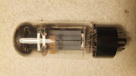
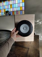
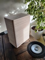
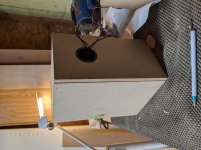
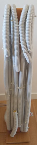
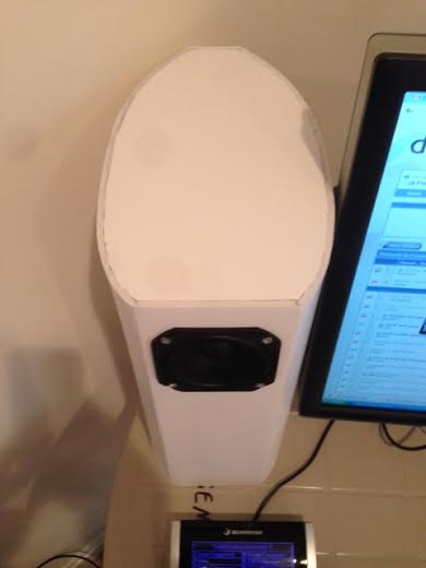
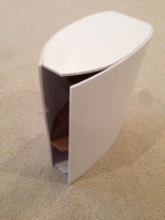
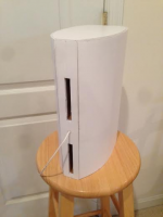
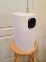
Here is the completed speaker:
404491d1394331762-foam-core-board-speaker-enclosures-dcr-vifa-photo-01.png


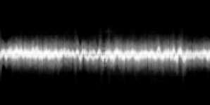
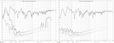
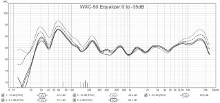
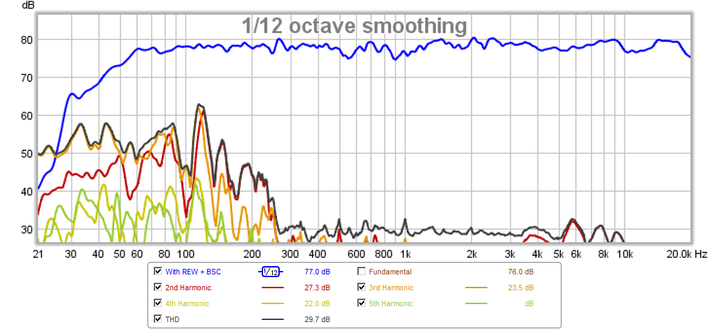
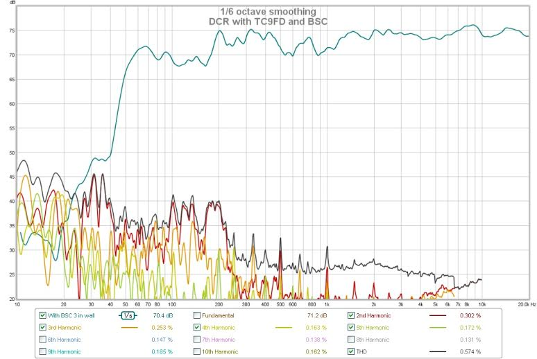
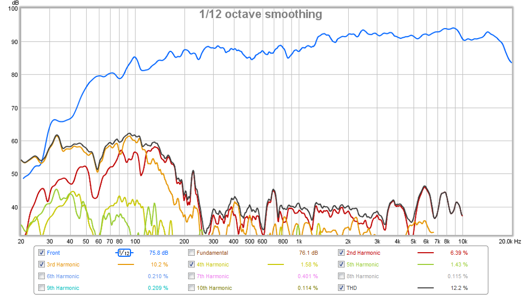
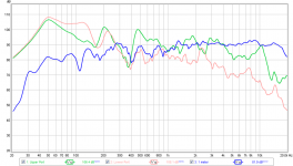
Preview of performance - here is what the FR and HD looks like with digitally applied BSC and bass smoothing with REW via miniDSP:
405087d1394537242-viva-la-vifa-curvy-cabinet-dcr-tc9fd-dcr-vifa-bsc-rew-hd.png


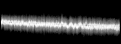
Here is the harmonic distortion performance with a speaker-level BSC and no DSP applied at the desktop listening position:
405849d1394805227-viva-la-vifa-curvy-cabinet-dcr-tc9fd-dcr-vifa-bsc-rew-hd-3in.png


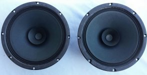
In doing this I wanted to try a dual chamber reflex (DCR) - an alignment I have not tried before. Maybe not the best driver for a DCR, but I am using the venerable Vifa TC9FD to see if I could build a bold looking single point source with some decent bass as an all-in-one solution for excellent bookshelf, desktop, or even lower-volume stand-mount duties. I was not sure if it is possible with TC9FD, but my ultimate goal would be to be able to build a mini-monitor with flat response and low harmonic distortion (-20 dB) down to about 80 Hz, and better than -40dB HD above 300 Hz where the vocals and telephone band are.

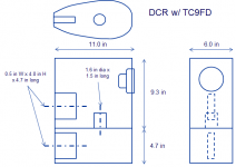
I started with a model of the DCR in Akabak and used a typical volume required for such a high Qts driver like the Vifa. I also tried to keep in mind what a useful size would be for desktop of bookshelf speaker and set on no more than 14 in (35.6) high x 11 in (28 cm) deep. I set the width based on the minimal volume required to achieve significant bass extension (recommended volume by WinISD is 15 liters), while still keeping the profile small and attractive. I settled on a 50 Hz tuning frequency to really push this design below the 55 Hz tuning limit suggested by WinISD for BR design for a driver with an fs of 120 Hz. The HD may be terrible but we will have to see how it works out for nearfield (1 meter) listening at moderate 70 to 75 dB levels where cone excursion may be quite small and HD may not be too bad.

I arrived at a design that was about 12.5 liters total volume with dual ports each having 2.0 square inches (~13 cm^2) of CSA and a vent length of 4.7 inches. The volumes would be divided using the standard DCR design practice of 2/3rds for the upper chamber (where driver is located) and 1/3rd for the lower chamber. Normally, the interconnecting port is the same length but in the model I found that reducing its length helped to smooth the response in the 150 Hz region. So the interconnecting port is the same CSA but only 1.5 in (3.8 cm) long. In order to get an approximate volume required and have curvy corners, the maximum width was set at 6 in (15.2 cm) wide.

But there is another aspect to the design that I always consider: using the minimal amount of FC material as possible and making it so that it looks seamless from the front. I sketched the truncated teardrop (or airfoil) shape on a piece of paper ensuring that the flat front was wide enough to mount the Vifa - so I set it at 4.0 inches (Vifa is 3.5 in wide). I then rolled the template along a length of FC board to trace the circumference of the shape to make sure I could fit. With a little trimming I was able to achieve a shape with nicely rounded front corners, a gradual slope towards the back, a flat on the back for mounting the rear firing slot vents (and I think it looks better than a sharp knife edge), that fit in a 30 in long FC sheet length with exactly a strip equal to the rear flat left over. That is, the circumference of the speaker including the back is 30 inches. I had considered making the speaker 15 in tall but making it 14 in tall saves 6 in of material that will be needed for the top and bottom panels. The middle divider is not visible so I made that out of double wall cardboard. So this is a "1 FC sheet" design (or $1 in FC). This time, I only had the nicer thick paper facing Elmers FC on hand so I used that instead. It provided a much sturdier build and I would suggest that others use this too as it substantially improves the strength and durability of the structure once done.

The construction method is fairly simple but may be tricky for those new in FC construction. I would not recommend this as a first FC speaker build as the curved wall construction requires some experience. However, you can certainly practice and it doesn't cost anything if you mess up.

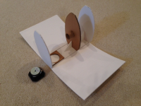
Start by cutting 3 of the rib shapes which define the internal curves. Locate that on a sheet of FC to establish where the two rounded corners are on the front. Then score cuts along along the 14 in length direction every 3 to 5 mm piercing through the first layer of paper with a razor. You will want a straight edge (or a metal drywall "T" is the perfect too to make this go fast) to make sure the lines are parallel. Do not score the flat 4 in wide section in front. The take a razor and remove a 1/8 in wide channel of paper and foam from the corner where the front is to allow a clean fold that does not crunch the paper. Now use a rounded object like a PVC pipe, a radiused countertop edge, etc to pre-curve the shape to allow it bend and wrap around the ribs without too much effort, being careful not buckle it and crease the FC this ruining the piece. Check that the curve can sufficiently follow the curve on the rib without too much force.

404867d1394457584-viva-la-vifa-curvy-cabinet-dcr-tc9fd-dcr-vifa-photo-03.png


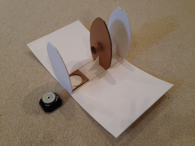
Now glue the 3 ribs to the correct locations on the sheet (top, bottom, and 4.7 in from the bottom), add 90 deg braces to the ribs to set the squareness and reinforce them for the next operation. Then add a second layer of either FC or double wall cardboard behind where the driver goes to give the screws more material to grip.

404870d1394457584-viva-la-vifa-curvy-cabinet-dcr-tc9fd-dcr-vifa-photo-05.png


Now here is the tricky part, start gluing the outside panel to one side of the ribs a section (half the length from the front) at a time. You need to make sure the hot melt glue gun has a full stick of glue to start the operation (or have a spare ready and held in your teeth to reload quickly) as you do not have much time and there are 3 strips of glue about 5 inches long each that need to be applies, in addition there is the 14 in long gap where you removed the foam from the crease that needs to be filled with hot melt glue. Once you quickly apply the glue, use your hands to firmly hold and clamp the panel to the ribs to ensure a tight fit (including the middle divider rib). You only have seconds to work and hold it for a good 45 seconds before releasing pressure. Now use the glue gun to add fillets of hot melt glue internally to the joints to make an airtight seal. Next, repeat the hot melt glue and clamp with the remaining length all the way to the rear of the speaker. You may notice that because the speaker is curved and rounded, it is hard to hold steady while you apply hand clamp pressure. You may need to employ your knees, lap, and carpeted floor in combination. It wants to roll and squeeze its way out of your hands as you clamp it. Again, add hot melt glue fillets to seal.

404868d1394457584-viva-la-vifa-curvy-cabinet-dcr-tc9fd-dcr-vifa-photo-bracing.png


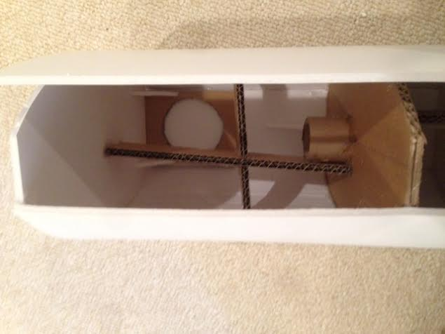
Now repeat with the remaining side, but before doing so, add some internal bracing to reduce the drum head resonances on the large side walls and the top and bottom panel. I used cardboard trimmed to size. You have to wait until the final side panel is glued on partially before adding final side bracing. If you have small hands (and a small hot melt glue gun) there is enough room to squeeze inside and seal the joints on the second panel before gluing the final stretch. On the final stretch, you have to apply copious amounts of hot melt glue to the divider rib because you cannot get to it after the fact so ensure an airtight seal there. The end ribs are not as critical as you can still seal it from the outside as needed.

404871d1394457584-viva-la-vifa-curvy-cabinet-dcr-tc9fd-dcr-vifa-photo-04.png


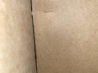
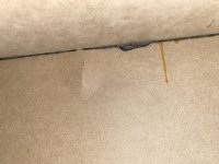
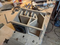
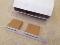
Once you have the curves single piece wrap around side on, it looks like a real speaker. Now trim the rear wall to have beveled edges to fit perfectly into the gap created by the one piece wall, cut two port slots (0.5 in x 4.0 in tall) in the rear wall. Make two slot ports out of FC or cardboard using hot melt glue and then glue them to the back of the rear wall strip. Either use binding post mount or poke a small hole and feed the speaker wire through the rear wall and seal with hot melt glue. Cut the driver hole with an xacto (it is 3.0 inches dia exactly), make sure you have enough wire coming out the front and attach crimped quick disconnect terminals. Add moderate stuffing to the top and bottom chamber (I used pillow stuffing) being careful to not directly block the vents. Then glue the rear wall on - the speaker is now finished except for the BSC circuit.

404872d1394457584-viva-la-vifa-curvy-cabinet-dcr-tc9fd-dcr-vifa-photo-02.png


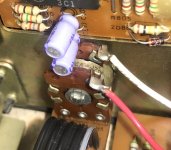
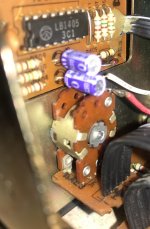
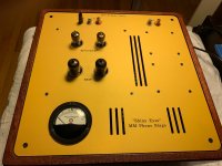
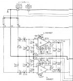
Install the driver using wood or drywall screws. For those wanting to go the BSC route, put a 1.0 mH air core coil plus a 10 ohm x 10 watt resistor in parallel plus an optional 0.47 uF capacitor in parallel. Put all this in series with the posititive terminal to the driver. Hot melt glue this somewhere in the chamber (preferably at the bottom for stability) before you seal up the speaker.

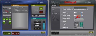
I am going with the EQ'ing the speaker through my music player on the PC for now until I can get the BSC. It sounds really nice and I think you will like it and agree that the clarity and imaging will be superb. The bass is sufficiently deep at about 50 Hz when the speaker is placed near a rear wall such as when used as a bookshelf or desktop speaker. For in stand mount duties away from a wall, a sub woofer will most likely be needed to get sufficient bass.

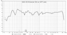
Here is the Freq Response from the ports and the integrated sound - far from walls:
404874d1394457660-viva-la-vifa-curvy-cabinet-dcr-tc9fd-dcr-1-meter-integrated-ports-no-bsc-spl.png


Here is response close to a wall and at 0.5m away and lower drive voltage:
404877d1394458995-viva-la-vifa-curvy-cabinet-dcr-tc9fd-dcr-integrated-no-bsc-spl-hd.png


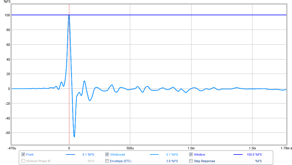
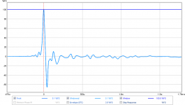
Here is the Impulse Response:

404878d1394458995-viva-la-vifa-curvy-cabinet-dcr-tc9fd-dcr-impulse.png


I will build the matching stereo pair as soon as I get some time (about 4 hrs to make a piece) and more FC. have a listen to the sound clip and I think you will agree that it is a great sounding near field desktop speaker, or computers speaker.

404584d1394377264-foam-core-board-speaker-enclosures-dcr-vifa-photo-06.png


404601d1394377728-foam-core-board-speaker-enclosures-dcr-vifa-photo-07.png


Cheers,
X

Sound Clip Here:diyAudio

Attachments

  • DCR-plan.png
    DCR-plan.png
    20.9 KB · Views: 3,435
  • DCR-Vifa-photo-03.png
    DCR-Vifa-photo-03.png
    514.6 KB · Views: 7,211
  • DCR-Vifa-photo-bracing.png
    DCR-Vifa-photo-bracing.png
    279.3 KB · Views: 6,756
  • DCR-Vifa-photo-05.png
    DCR-Vifa-photo-05.png
    210.7 KB · Views: 7,270
  • DCR-Vifa-photo-04.png
    DCR-Vifa-photo-04.png
    549.6 KB · Views: 8,333
  • DCR-Vifa-photo-02.png
    DCR-Vifa-photo-02.png
    163.3 KB · Views: 6,688
  • dcr-1-meter-integrated-and-ports-no-bsc-spl.png
    dcr-1-meter-integrated-and-ports-no-bsc-spl.png
    85.7 KB · Views: 8,576
  • DCR-Vifa-photo-01-hr.jpg
    DCR-Vifa-photo-01-hr.jpg
    109.1 KB · Views: 369
  • dcr-integrated-no-bsc-spl-hd.png
    dcr-integrated-no-bsc-spl-hd.png
    129.8 KB · Views: 7,446
  • dcr-impulse.png
    dcr-impulse.png
    42.4 KB · Views: 6,960

ZV7R rebuilding

Hello! It’s been fifteen years since I built my ugly lovely ZV7R with a lot of help from forum members.
Although it sounded wonderful, it is too large to keep in my narrow room. So I disassembled it and I’m currently rebuilding a bit smaller one.
My question is if I use 40V power supply, what is the best value of the voltage at gate Q3(4V), drain Q3 (5V), gate Q1, Q2 (9V), and drain Q1, Q2 (20V)?
What I could adjust were gate Q3=4.9V, drain Q3=5.6V, gate Q1, Q2 =9.9V, and drain Q1, Q2=21V.
Thank you.

Aleph J Trouble

Greetings All,

I'm trying to get an Aleph J build running and while in the homestretch I've hit a snag that I'm not technically savvy enough to resolve myself. I'm good at following directions, but a lousy EE.

My trouble: One channel is functioning as expected, and I've been able to zero the output and set the bias, but the second channel is sending V+ (25.7V) to the output. Messing with R7 has no effect.

What I know:
Swapping power supplies has no effect.
I measured each resistor before populating the boards.
Q2, Q3, and Q4 are oriented correctly, though untested.
I'm using 2SJ74's instead of the 2SJ109. Also oriented correctly but untested.
Gate voltages on Q5 and Q6 read +25.7V and on Q7 and Q8 read -25.7V.
On Q5 and Q6: Source and Drain voltages are approximately equal at ~25.6V.
On Q7 and Q8: Source reads -25.8V but Drain reads +25.7.
I haven't seen any smoke from any of it (yet)😀.

I'm not sure where to go from here and hope someone with more familiarity with the amp/board/electronics-in-general would be willing to share their wisdom. No suggestion is too rudimentary as analog electronics is entirely new territory for me. I have extras of most components for swapping as appropriate.

Thanks very much in advance, all.

DC voltage on channel outputs (Faulty Yamaha receiver)

Hi guys,

I'd like to say in advance, I'm not very savvy when it comes to electronics. My background is in software engineering, but I like solving problems(and saving money) and this is my dads old amp, so I'd really like to see if I try and fix it.

The problem:

I have a Yamaha RX-V340 RDS, that is going into protection mode on startup. In the diag menu, the error log reads: 'DC PRT 14%' (The percentage amount sometimes fluctuates between 9 and 16%), which according to the service manual means "The DC output of the power amplifier is abnormal".

My deductions so far:

When putting the amp into protection override, I'm measuring DC volts on the output terminals of -1.4V on the RR, R, L and RL channels. Basically everything except center.

Initially I was told it could be a DC offset adjustment issue, but after looking there are no potentiometers on this board, so I'm not able to adjust that.

My board has 3 big 'IC's. One for center, and one each for R and L, which contain the outputs for both main and rear within them. From the service manual(schematic on page 56) I can see that the outputs for the rear and main channels of a single IC should all read roughly zero, however I'm getting -1.1V on all. That must be related to my +- -1.4V on the outputs, no?

It's also worth noting that I'm not getting the expected (roughly) -40V on pins 5 and 12 on either IC302(R) or IC303(L), and also not on pin 5 of IC301(C). Instead I get around -1V on those. I'm not sure how this could be related, but it does seem pretty far off from where it should be.

This all makes me think there is some issue upstream from the each channels power amp, since they all have similar problems. But then again, I am not too clued up here.

Am I on the right track? Any ideas for things to try which might narrow it down?

Service manual: Download Yamaha RX-V340 Service Manual | ManualsLib

Thanks for your time!
Rob

Valve/tube choices and understanding the simulation charts

I'm building an SSE (waiting for the board to reach me, so at the component collecting stage), and am being a bit dim with the simulations charts on the Tubes and Applications page;

Tubes and Applications | Tubelab

Essentially I'm not clear on what the columns are;

Tube Type - this is pretty obvious.

B+ voltage - is there a way that people estimate this from PT values? I know that different rectifier tubes make a difference, but I'm assuming there is more to it than that with chokes etc?

Load Z - I'm assuming this is the primary winding on the OPT (given the speaker load being as per the stated output value, or does this not matter? i.e. 5k/8ohm transformer with a 6ohm speaker no longer Load Z of 5k?)

Vp - Voltage but not sure what 'p' is. Plate was my guess, but it is just that.

Vk - Again voltage, but not sure what 'k' is

Rk - Resistance but still don't know what 'k' is...from the value I can see it's likely the cathode resistor. This may explain 'k' as 'cathode', but I'm guessing rather than knowing there!

Ik - Current of 'k'

Diss (idle) - power disipation at idle

Pwr Out - power out

We've then got distortion values at different points, but at this early stage I'm more trying to understand the process of choosing the glass and the bits to match it in terms of things being iside opperating values and nothing making smoke etc!

My real world situation with my initial build is that I've gone high on the PT (374bx - 375-0-375), but initially am trying to build it with some little 5w OPTs, so need lower power output numbers from higher B+ numbers.

The first thing I think I need to understand is how to work out the likely B+ values based on what bits go into the power supply - is there a simulator for this?

I've built a few vale bits over the years (5F1 clone, 18watt clone, Bottlehead Crack plus mods etc), but Im hoping to come out of this with some more first principles based understanding of what and why, rather then just buidling from a parts list because someone else said it works! 🙂

Optimally driving a (VPI) synchronous turntable motor

Driving a synchronous turntable motor needs two signals 90 degrees apart, generated with a stable 50Hz/110V or 60Hz/230V frequency depending on the country where you live.
The simplest way is to use the local mains frequency and a capacitor to do the phase shifting for the second phase.
The mains frequency however is most of the time not being a perfect sine shaped wave and may be further polluted by many high frequency peaks caused by domestic equipment, apart from the fact that the mains frequency is jittering around the nominal frequency caused by varying loads in your local area.

Stable phase shifting by means of a capacitor works only when 1) the input signal is a perfect sine shaped signal and 2) with a non-varying load. None of both is true when feeding the motor directly from the mains supply.

To have a better situation to start with, VPI offers the SDS, a device that is producing a stable sine shaped signal to directly drive the motor, thereby isolating all problems that comes with the mains supply.
However, phase shifting needed for the second motor drive voltage is still done by the same capacitor as before. Since the load that the motor presents to this capacitor is not stable, the second phase will be a jittering signal leading to torque changes and hence to rumble.


Linn with its well praised LP12 turntable, uses the Lingo power supply to provide the two motor phases electronically, thereby ensuring a perfect constant torque motor drive, preventing the need to use a super heavy platter to damp the motor vibrations.
That a capacitor is not the ideal component for making the second phase can be shown with a so called Lissajou figure, by offering one phase to the X input and the other phase to the Y input of a scope.
Two sine shaped signals, each 90 degrees apart, will result in this way in a perfect circle.
Zero degrees phase shift will result in a straight line, tilted 45degrees and all phases in between will result in an oval shaped, but only if the phase shift between the two phases is constant all the time.
If the phase shift is not constant, it will result in a distorted oval or circle.

So lets have a look at the Lissajou figure of the phases directly on the motor driving a VPI Scoutmaster.

220V-Condens.jpg

So what you see is a distorted oval, telling two things. Because it is not a circle but an oval means that the phase shift is not 90 degrees, causing the motor to have less torque.
And because of the distortion of the oval it is obvious that the phase shift jitters, and so does the motor thereby causing rumble.
The solution is of course the way Linn did it by supplying the two phases instead of just one, and to get rid of the dreaded capacitor used for this function.

Block Diagram.jpg

The 50/60 Hz generator can be made in many ways, to give a few examples:
- precision sine wave generator
- digitally, starting with a Xtal osc, dividing to 50 or 60Hz, then bandpass filtering to get a sinus shaped signal
- using a uProcessor and let the internal D/A convertor generate a sinus
In my case I used a Project Speed box that is using the third example and generated a signal of 50Hz and 67.5 Hz for 33 1/3 and 45 RPM, but it will be pretty easy to use some low cost uP and do the programming yourself.
Depending on the quality of the signal you may have to add some filtering.

Then comes the phase splitter.

Phase Splitter.jpg

The frequency where the phase shift is 90 degrees is 1/(2 x Pi x R3 x C1).
In the example above this is 50Hz.
By changing the value of R3, you can alter the 90 degree phase shift point to your need.
You could even add a second resistor plus a switch parallel to R3 to be able to switch between 33 1/3 and 45 RPM.

Gain of this splitter is 1X, so both phases have the same amplitude. It is therefore wise to have a signal coming from the generator that can be varied in amplitude, this will affect both phases.

Next in line are the 2 amplifiers steering the turntable motor.
You could make your own design for a 110V or 230V amplifier, which can be done, but it is not the easiest way.

What I did was to use a cheap (second hand) stereo amplifier and feed it with the signals from the phase splitter to get an output signal of 15 Volt, by varying the amplitude of the generator output.
The output of the stereo amp is fed to two small 15V/230V toroid trafos that are directly feeding the turntable motor.

Again displayed as a Lissajou figure, this is how it looks.

two-phases.jpg

Hans

SBAcoustics 61-NRXC with SB17NRX2C35-8

Hello, I'm intrested in building this open kit SBAcoustics-61-NRXC with newer SB acoustics woofer SB17NRX2C35-4 (main reason beacause I already have drivers🙂).
I read this article www.audioexcite.com >> Blog Archive >> SB17NRX2C35-4 vs SB17NRXC35-4 and how I understand drivers almost interchangeable but still need some tweeks. In past builded couple of kit's but never designed a crossover. So how could I figure out those tweeks ? Just try to put this crossver in some sort of crossover design software ? And also in the article is this sentence "Also, another factor to consider is that if combining the two NRX versions with the same tweeter, the drivers relative acosutical off-set is about 3-4mm larger using the new NRX2 driver compared to the old NRX driver." What is relative acosutical off-set? Information that I managed found myself was to technical to understand.

PHL 1160 vs 1040?

I have a chance to buy a pair of 1160 but already have a pair of 1040s that I found to be very nice when listening to the naked driver (free air, no XO).

Of course, PHL don't ever publish FR and impedance curves. From what I have gathered from various international forums (fora?), the 1160 has the same FR as the 1060 which has the same FR as the 1040/1050. Toutehauteparleur has a blurb that the 1160 has slightly better bass extension.

What I can see from the data sheets (1160 compared to 1040) is
- loss of 3.5 dB of efficiency
- half a mm more x lin
- virtually the same fs
- slightly higher Qts

Have I missed an obvious upside or downside?

Triad Transformer Official Archive - name change

Triad Transformer Official Archive - name change

The official Triad Transformers web archive (their fine old catalogs, generously hosted) has had a name change.

Please dis-use "http://www.triadtransformers.com/"

and now use "http://www.triadtransformer.com/"

The site with the original name, containing the "s" at the end, now leads to a garbage link farm. A speculation would be that a sleazy person used an ICANN technicality to take the original url from Triad without consent or notice. But no point in speculating.

Wishlist: Op Amp Characterization Curves in Datasheets

Since it's the holiday season I thought a wishlist thread would be appropriate! So what additional characterization curves do you wish to see added to op amp datasheets in the future?

I'll start the list:
THD for high source impedances to characterize input impedance linearity
FFTs of the output distortion to show which harmonics are dominant

Philips CD610ii. Mods

I have a Philips CD610ii in great condition, for plastic.
CDM4/19 transport and TDA1543 DAC, only an 8 pin type, I'm guessing it's not as good as the TDA1541?
I have a Marantz player with the larger non A and a Rotel DCD-855 with the (A) that I'll also be having a play with. These are just for learning, I have a Wadia in my main system and a Parasound Pass Labs DAC.

I wanted to use it as a sample player to play around with, Opamps and maybe go a little further.

First I replaced the electrolytic capacitors only changing the value of the main smoothing cap only from 3300uF to 4700uF and the rest same values. Added 0.1uF ceramic capacitors to the regulators. Nothing major here

I then (for the first time ever) added some sockets for the Opamps and put the original LM833 chips in, gave it a good listen for a few hours. Swapped the LM833's out for trusty, brand new, NE5532's (many players similar to this have them).

Straight away they seemed brighter, had the sibilance around 8kHz that does my ears in. I gave it an hour or so but really is like torture to me that sibilance. I replaced back to LM833's. Sibilance was not there, or at least not as sharp.

I replaced the LM833's with the well respected LM4562's.
What have I been doing all these years? What an amazing difference. Sounds like a better player entirely.

The other two a lot more similar and easily can tell it's the same player yet I've 'upgraded' to more expensive players a lot in 25 years and not got that much difference more often than not.

Which OPA Opamps would you recommend? I'll try a couple more for now

I want to build a separate power supply with variable regulation, 317/337 so I can test Opamps at different voltages. I'll dig my scope out and adjust the implementation if needed.

stupid question about SPL vs power

Example:

I have two sets of speakers.

One is ~3R5 with 83db "typical in room" SPL (Micca RB42)
Two is ~6R with 95db "typical in room" SPL (Energy RC-70)

Assuming the same perceived volume, and the fact that I know it takes more power because I had to increase the volume to compensate, is that power just being wasted as heat in the crossover/drivers then? I assume yes, but I'm having a brain fart.

Help modeling “vintage” loudspeaker cabinets in WinISD

I’m fairly comfortable using WinISD but on my current project, I’m trying to reverse engineer the response of an Altec 605A duplex driver in the 612 utility cabinet. In the early/mid sixties this combo was often used as a studio control room mixing monitor. I found the Thiele-Small parameters of the 605A easily enough so I was able to add it to my WinISD driver inventory. The problem arises when trying to model it in a 612 enclosure (approx 6.8ft3); the 612 is an old school cabinet with a 5.375” x 13” cut-out but no appreciable “port length” to speak of, sans the 3/4” thickness of the ply that has the cut-out.

When I model it as a vented enclosure I cannot use the cut-dimensions as a rectangular port with a 3/4” depth (the depth is ghosted). When I model it as a sealed enclosure I cannot access the Ql parameters to make it look like a “leaky” sealed cabinet. If I model it as a vented enclosure but zero out the vent dimensions, the sim kind of falls apart and gives up providing useful data.

Any pointers here?

Novice questions to bass traps.

Hi folks,

Not sure if my questions are advanced or quite novice, but:

1. Let's say I placed one audio system in a definitive way. Afterwards of course I've located places in the room where the amplitude of some low frequencies is high. As far as I've read, this is where I should place bass traps for these frequencies.

2. But what if I decide to have a second system placed somewhere else in the room? Will the previous "hot spots" for treatment will be the same, or shift?

3. How should be the a bass trap placed if the hot spot is located at the corner of a tilted roof (vaulted ceiling)?

Best regards!

NAD C300 keeps blowing Mosfets

I've got a C300 here which was working well until someone accidentally turned up the volume up past halfway, which killed the Mosfets on the right channel, blown 2 fuses, and took out a rectifier. These Mosfets are like delicate little flowers lol I've fixed a few of these previously.

I've replaced the faulty rectifier and fuses with the same type.

I have stable and correct voltages on the output of the regulators.

The voltages at the Mosfets are:

Left channel (Mosfets measure good)
Q307
G, 2.3V D, 30.4V S, 0V
Q308
G, -27.7V D, 0V S, -30.1V

Right channel (blows Mosfets)
Q407
G, -26.8V D, 0V S, -30.1V
Q406
G, -2.3V D, 30.5V S, 0V

I have tested all the transistors and diodes in the right channel, pulled one leg from resistors and they all appear good. I even pulled the vertical line/driver board and all transistors and diodes measure good. I replaced the 22uF cap as it measured very high ESR. The emitter resistor tests well.

Fuses don't blow anymore yet R/C Mosfets blow on startup with no load.

The service manual is here NAD C300 Stereo Integrated Amplifier Manual | HiFi Engine

What am I missing? Much appreciate any guidance in advance

Mono outdoor upgrade

I am looking to make some upgrades the outdoor music system I had made a few years back. Currently I have echo dots setup around my property which send their audio to each other and one dot then sends the audio via 3.5mm cable back to an Sony amp running in mono mode. The amp then goes to a volume switch controlling each zone. I bought some new speakers which are capable of 300 watts / channel which is well above the 100 watt output of the sony amp. I also do not think the Sony amp is doing a great job at sending out mono audio. While I am upgrading I was debating changing the 3.5mm audio to a wifi and or Bluetooth receiver and changing the sony receiver to a more powerful one and maybe a biamp nexia cs for the mono audio control. I would also need a speaker switch that can handle the extra wattage and was looking at few by OSD. Currently I am thinking along the lines of Echo dots to bluetooth/wifi receiver to Biamp nexia CS to Amp to OSD. Is there anyway to combine some of these things into one device without getting a Sonos system?

audio research 100.2 trouble

Hi Guys,
i have a ARC 100.2 in trouble here. The muting circuit is always on and the led flash. I have 0V in gate of Q47, 0.06V in base of Q41,42, -7V in gate of Q44 and 0.6v in pin2 of U3. I d'ont understand the utility of the circuit with the optocoupler RY3. Someone can help me?

I found this schema on the net

Maxpou

Attachments

  • audio research 100.2 protect.png
    audio research 100.2 protect.png
    300.4 KB · Views: 133
  • audio research 100.2 amp.png
    audio research 100.2 amp.png
    505.6 KB · Views: 129

Adapting polyurethane adhesives for panel speaker applications

Hi all

I like the idea of polyurethane adhesives (e.g. Gorilla glue) for a number of tasks on panel speakers, but I would like it to be thinner sometimes (for applying) and to foam less or hardly at all.

I have read on another thread that acetone is an effective thinner, perhaps 1:1. Does it affect bond strength or foaming?

How about other relatively benign things: water, alcohol, lighter fluid? I'm not a chemist so if any of these are really stupid ideas then my apologies!

M

The Further Adventures of the 6p3p Kit - 12AT7 Driver Mod

Greetings, Friends. I've seen several older threads on this amplifier, but none seemed to touch on this mod, so Here Tis: I've reworked the 6p3p DIY amplifier kit available from a variety of online resellers to use Western tubes.
rLGAfBb.jpg


The original kit came with a pair of 6p3p power tubes, a 6n1 driver, and a 5z4p rectifier, or in my case the Soviet 5Ц4C. Here's the schematic that comes with the kit
1uvlszA.jpg


I found an older thread on this site dealing with this kit, and an improved design was produced by user Raindance. I've taken his pretty drawing and made 2 changes: by swapping the cathode resistors on the driver tube to 470R, we can use a 12AT7 as the driver tube. And the power supply section as designed is a tad hungry, so I've replaced the 47u with a 18u and the 330u is then replaced with the 47u to keep the rectifier from working so hard. I also have a 5uF mylar cap as bypass on the 47uF, but that's not mandatory.

I currently have it set up with an old GE 5R4GB rectifier and new Ruby 6L6GC power tubes, with a Ruby HG 12AT7 Driver. Sounds Great.
Uu41RWH.jpg

Symmetric preamp PSU using 2 positive PSU

Hi,

Makes it any sense to build a symmetric preamp PSU using 2 positive PSU in series?

I've build a PSU using one positive and the complementary negative PSU. LM317 + LM337 & IRF510 + IRF9510 cap multiplier. Shunt regulator part is identical.
The issue here is that it needs a lot of tweaking to get output voltages within 100mV the same.

I know the 317 is better than de 337 part. But does the circuit as attached is really better than using a positive and a "real" negative PSU.

Attachments

  • Symm preamp PSU.JPG
    Symm preamp PSU.JPG
    110.6 KB · Views: 246

Second attempt at Building my own amp from scratch

Ive been reading this forum and have greatly enjoyed all the experience of the members here.

Here is my 2nd attempt this time I really want to learn.

Criteria is a 100W amp into 8Ohm, with acceptable performance,
I dont expect a great result as this is a first and very new to me.

I wanted to keep it simple. I drew have 2 circuits,
Ive made a toner transfer pcb of the first circuit and will build it as
time allows.
The second circuit is just a thought, to be more flexible at various supply voltages.
Ive only spent about 2hrs on second circuit.

Pls inform of changes I should make.
Ive tried to do the best I can, but I need advice.

Attachments

  • 1.schematic.jpg
    1.schematic.jpg
    180.1 KB · Views: 1,474
  • 1.pcb.jpg
    1.pcb.jpg
    361.2 KB · Views: 1,400
  • 2.schematic.jpg
    2.schematic.jpg
    179.3 KB · Views: 1,352
  • 2.pcb.jpg
    2.pcb.jpg
    438.2 KB · Views: 1,289

Cambridge Audio P60 Repair

I'm working on a Cambridge Audio P60, which puts out a very loud buzz on all outputs, including headphones. Unfortunately it's a massive struggle to get anywhere, as the schematic available does not have a board diagram, and bizarrely my P60 does not have part labels on the board! So none of the components are named and therefore it is very difficult to know what is what according to the schematic.

Has anyone experience with working on one of these who could help me out?

Many thanks,
R.

Symasym - the next generation (supersym)

After many E-mails and even a few download attempts at my "supersym" PCB ( It's not done yet.. have patience :bigeyes: )
, I am starting a new thread to : 1. Share the existing amp (PCB and construction advice) , 2. Design a professional board that will maximize performance and fidelity. , and 3. develop it further with JFET inputs (anatech's suggestion)and a MOSFET OPS.

The design as it is now...
An externally hosted image should be here but it was not working when we last tested it.


It has been the best sounding by far of my DIYA creations.
It stays biased within 2mv , any environment , drives paralleled 15" 3-ways all day at full volume .. no turn-on thump , completely stable in every way. 😎

The base schematic is here ..
An externally hosted image should be here but it was not working when we last tested it.

I am using C21 as my HF compensation. I have a 470K in place
of c6/r13.
Attached is the LT file to see for yourself (all models included). Make sure the "supersym .txt" in the zip file is in the same directory as the .asc file (models)..
OS

Attachments

Projects by fanatics, for fanatics
Get answers and advice for everyone wanting to learn the art of audio.
Join the Community
507,772
Members
7,887,917
Messages

Filter

Forum Statistics

Threads
406,206
Messages
7,887,917
Members
507,772
Latest member
Hypertone