I spend a lot of time listening to music of all kinds. For my needs, SPL 80-90 dB, in a small room 4 x 4 x 3 meters, my prototypes work fine. As a DIY I've always worked with full-range systems. I use two unconventional acoustic loads at the same time:
- a frontal one (MDDFL) to make the emission at high frequencies omnidirectional,
- a rear one (MDDBL) for medium-low frequencies which I think can also be sized for a sub.
At the moment I don't need to build a multi-way system. I want to report my prototype for an opinion on the use of the MDDBL acoustic load for a sub-woofer.
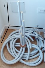
An image better explains a concept of many words. You can see a possible shape of the sub in the prototype MDD3H240, 8 waveguides in spiral sheath for electrical systems, are between 1.2 and 2.4 meters long. The guides are fixed to a one meter high wooden and aluminum support. An earlier prototype 22C71L8 resembles a giant squid with 8 tentacles. With a 3 ”driver, the 3FE25 from Faital-Pro can reproduce 40 Hz in small environments down to about 90 db.
The use of flexible waveguides would allow the guides to be folded into a cube, to position the guides inside a wall or a piece of furniture in the room. The waveguides have different lengths to which different resonances correspond, it is possible to position the outputs in different positions to optimize the interaction with the resonances of the listening room.
The MDD3H240 prototype has a compression chamber 80 x 80 x 80 mm, 8 waveguides in 25 mm spiral sheath are fixed to the chamber. If we consider the system as a whole it has a closed side, the resonances are between: c / (Lmax * 4) and c / (Lmin * 4), as in TL. If we consider the individual waveguides, they are open on both sides (external and compression chamber), in this case the resonances are between: c / (Lmax * 2) and c / (Lmin * 2). By inserting a cube of foam rubber at the end of each waveguide, the merit factor Q of the individual waveguides is reduced, the resonances partially overlap and compensate each other. In my prototypes, the lengths are distributed over an octave with a logarithmic series.
Thanks for your attention, I am available to anyone who would like more information.
https://www.claudiogandolfi.it/
https://www.claudiogandolfi.it/mdd3a89.html#h
https://www.diyaudio.com/forums/pla...idirectional-single-drive-17.html#post6599019
Attachments
Last edited:
Interesting speaker designs! Does it sound like a conventional speaker with the sources arrayed vertically like that?
The rear wave from the two-sided Rice-Kellogg driver has been the "tail wagging the dog" for 100 years. It has shaped virtually all thinking about low freq. A lot is driven by an exaggerated fear of wave cancellation that is stronger on textbook diagrams (esp with circular baffles) than in real rooms.
So I think it is important to be creative about dealing with the rear wave - as this thread introduces - instead of endless nit-picking about port sizes.
Long pipe to sequester rear wave
B.
So I think it is important to be creative about dealing with the rear wave - as this thread introduces - instead of endless nit-picking about port sizes.
Long pipe to sequester rear wave
B.
Interesting speaker designs! Does it sound like a conventional speaker with the sources arrayed vertically like that?
In an array with vertical drivers the emissions are simultaneous, the MDD emissions have increasing delays. I have no experience of listening with arrays, I can say that the MDD emission with multiple delays helps to perceive a virtual emission with a much greater volume than one would expect from a 3 "driver. Another factor that contributes to perceiving a much larger image than the driver. In the MDDBL acoustic load each waveguide has a different resonant frequency and an emission point at a distance of about ten centimeters from each other, different frequencies also have different emission points in space.
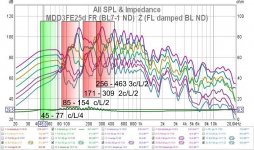
I am attaching the graphs of the measurements made with the microphone at the output of the individual waveguides of the MDDBL acoustic load of the MDD3FE25d project. The microphone positioned at the output of the waveguides partly interferes with the emission but the peaks relating to the resonances between c / (Lmax * 2) and c / (Lmin * 2) are clearly noted. The individual emissions have an irregular trend but the various peaks compensate each other and the listening is very good.
Attachments
Right. The stochastic advantage of multiple different lengths should be very beneficial. But odd to my eyes that the bumps seem to align a bit instead of be all over the place. There may be common elements causing those alignments.
On the other hand, you can get the same sort of advantage by simply having (1) an irregular baffle, (2) one that mixes different path lengths rear to front or (3) canny use of wall reflections which is all but inevitable in any dipole mounted properly away from the wall.
While I get along fine with random mixing in life, others may find the engineered approach of this thread more appealing.
B.
The alignment of the peaks derives from the series of lengths that I have chosen for the waveguides of the MDD3H240 project. The series is calculated with the inverse formula of the logarithmic distribution of the notes. Using the Excel-like style notation, with i = 0, ..., N where N is the number of waveguides:
f = fr * POWER (2; i / N)
replacing Lmax = Vsuond / fr and L = Vsuond / f the lengths are
L = Lmax / POWER (2; i / N).
On a logarithmic scale, the peaks dependent on the length of the waveguide are evenly spaced.
The responses of the two channels are made asymmetrical by the arrangement of the furniture in the listening room. Paths of different lengths could also be created by taking advantage of appropriate baffle shapes and the position of the speakers in the room. With a folded waveguide it is easier to manage lengths of 4 - 5 meters.


