Hi all!
I thought I'll do a quick write up on what I've found out the other day - programming the CSR8675!
The CSR bluetooth chips are the most well known BT modules out there on small china amplifiers. Although the Chinese are outsourcing for a cheaper chip, the CSR BT modules is still a much better option when it comes to changing parimeters or eq. Some CSR versions even have a test app where you can change some eq settings on the fly! (Only known to work for CSRA642xxx and CSR867x).
The reason why I'm doing this write up is because I've struggeled to get the CSR8675 modules to be programmed by any software. This is because both the software and the firmware on the modules have to match to work, and they often don't! I've also spent tons of time trying to find the most up to date version of the ADK, but had no luck in fining an ADK that matched the firmware on the BT receiver I had. Then I came across TinySine and they write up on their BT 5.0 modules/amplifiers. They also use the CSR8675, and was kind enough to send me the firmware for their products. This made it possible to flash the module with a firmware that would work with the ADK they had posted on their site.
Just to give some pros and cons on the CSR8675 modules:
- Transmitter and receiver mode, up to 100x(?) can be liked together, not just TWS where it only supports 2 connections.
- More feature for DSP in the CVC software, including crossover and dynamic bass adjustment (key point for me, still testing it)
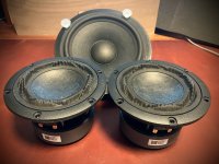
- 3 analog outputs (L, R, SUB)
- Working audio prompts (.wav files to be played on events, not just beeps)
- APTX-DH
- Some issues with connecting to the programmer, needs to be reset by PS tools to properly connect sometimes
- New software, no other writes up on it
So lets begin. First off, go to TinySine's web page and read up, that will give you a jump start on what I'm taking about. I would also recommend to just go for the CSR64215 if you don't need the advance DSP settings or multi connection. The CSR64215 can do EQ, TWS and APTX and is much more stable to program and use. There's also some amplifiers you can buy on ali that uses the CSR64215:
My fav CSR64215 amp combo:
Note: even got a working AUX input that is routed through the CSR chip, so you get seemless switching between line-in and BT. You're EQ/DSP settings also work when you route it through the CSR chip! Also got connectors for LED, BTN etc. I love using the LED on a BT switch for my speakers, you can create cool patterns to let you know what's going on.
More generic, and a little cheaper:
Note: does not have AUX in, nor breakout for an LED.
I do not recomend to go for neither the CSR8630,-35 or -45 unless you don't care for changing anything. You can do it, but they do brick easily. It is possible to get them to work if you brick em, but just don't...
Quick tip:
If you only want to change the name, you can use a generic USB SPI FTDI programmer and use PS tools to change the name. Take a look
here for more info. For any other changes, you do need a dedicated
USB to SPI adapter from CSR.
Info to get you started
Change Name:
EQ settings:
https://www.tinyosshop.com/index.php?route=information/news&news_id=86
Restore for older versions: (8635,-45, A6215)
https://www.tinyosshop.com/how-to-restore-bluetooth-audio-module-default-settings
For other great CSR info in video format, visit
Darie on YouTube, a great friend and CSR-BT master!
------------------------------------------------------------------------------------------------------------------
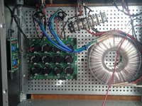
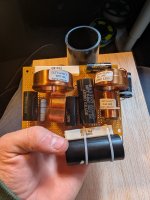
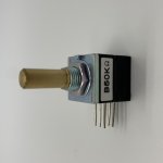
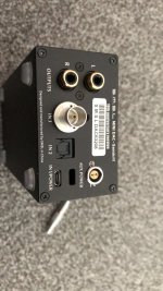
Now, to get going you will need a
receiver. There are some other breakouts and they will work, you just might need to change some of the PIO's. Also, you WILL need a x64 bit version of win to get the software to work properly, I've tested it with win10.
Firstly, go and download the tool at TinySine, the ADK 4.3 is all you need. You can also fin the software in my dropbox folder along with a lot of other info regarding CSR, both software and a ton of documentation. It's kind of messy, and I will add more of the CSR stuff I got laying around.
Dropbox heaven for CSR
EDIT 18.02.21:
Google Drive folder
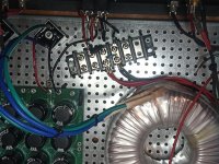
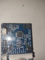
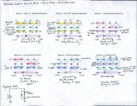
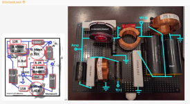
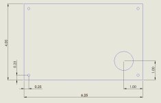
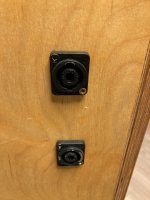
Secondly, to be able to do some changes you need to connect the programmer to the module, there's kind of a "standard" layout on most BT amplifiers/breakouts for SPI.
G -GND
V -VCC (3v3)
E (blank) - SPI enable (connect it to 1v8 or with a resistor to 3v3)
I - MOSI
K - CLK
B - CSB
O - MISO
Next is to burn the correct firmware on to your BT module. This will make the module exactly identical to the TSA6175 that TinySine is selling. One thing to note is that you need to do some changes if you're doing to to this to several modules. The main issue with copy-paste the firmware is that every BT module has the same address and is identifies as the same device. This is not a good thing. I will explain how to fix this after you have burned the new firmware:
Find the folder called "8675_firmware" and copy it. You will then need to open "BlueFlash". Connect the module to the SPI and the software should prompt the SPI converter. Click on "Stop Processor" if your BT module is running. When the module has stoped, find the folder with the firmware and click on the "dump" file. Clock on download, and the software should do the rest. Your module is now updated and you should be able to use the "ADK Configuration Tool" to change buttons and the general behaviour of the module!
To make every BT module unique you will need to open "PSTool", connect through the SPI and when you have read the chip you will be prompted with the BT modules address. Just change the value (change a 1 to a 2), click on "Set" and you're good to go!
To test if everything went well you should be able to connect to the BT module we just updated. To do this on
this module you will use a wire between "KEYCOM" and "vol-". First turn the module on, you should hear a sound. Double tap the "vol-" with the wire and you should hear "pairing". If not, use the wire to single tap KEYCOM and "NEXT" then do the "vol-" double tap. This will set the module in receive mode and in pairing mode. If you tap the "PREV" you will go into transmitting mode. I've not tested anything else at this point than receive mode. "The name will be "CSR6875" if you got it into pairing.
To change the name or any DSP settings follow the guides at TinySine that was given above.
Last part in this tiny guide is to pull up the "ADK Configuration Tool". Here you can use it to change mot of the setting. Be warned, some settings can cause if to not work properly, but no worry, if everything goes south, you can always reflash the firmware and you're on safe ground. Try to stay away from most of the settings except the once in "User Interface" that seems to be the most safe. Also DON'T delete all the settings under "User Events" etc, leave at least one if not you WILL brick it!
Have fun, and let me know if this was helpful. I would recommend watching YouTube videos and read up on things before you mess up. You should be able to fix a bricked module, but it can be a pain. Just ask questions if something was unclear, and I'll try to explain it. Do take a look in the Dropbox folder, as it contains a lot of info and some pictures.