Last year I struggled to mark a frontplate made from solid brass. The process involved countless tries and errors and turned into major project itself. Since I documented my findings in my private wiki, I thought it might be worth sharing them here as well.
The situation
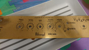
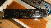
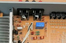
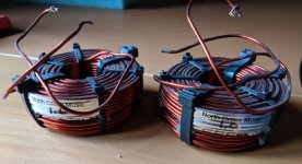
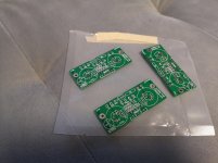
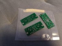
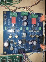
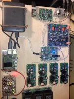
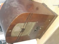
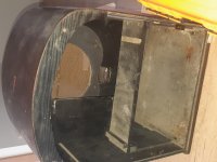
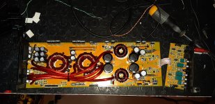
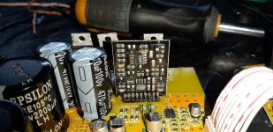
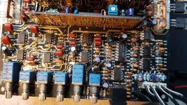
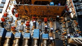
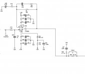
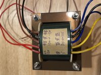
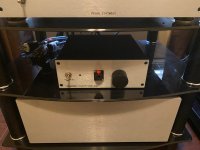
I bought a diy-ed preamplifier on eBay that came in a custom made housing made only from solid brass. It was "untested" and completely unknown to me. The brass however sparked my interest right away so that I could not resist and bought the thing for little money.
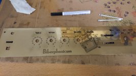
The brass definitely needed some cleaning and polishing. As far as I could tell the scales and lables on the frontplate had been made with rub-off letters. It looked quite impressive, but unfortunately the letters would come off immediately when polishing the metal. In fact the brass would even need some serious sanding before I could even get to polishing.
I therefore needed a way to apply new markings and labels. Preferably something that would withstand future polishing and would not ruin the distinct look of the brass.
I looked into a whole variety of techniques including engraving, toner transfer, mod podge, laser engraving and what not. But nothing seemed to fit my toolset or expectations.
TL;DR
The solution I came up with involves a combination of laser etching and acid etching (just like we used to etch PCBs in days gone by). I own one of those cheaper Chinese Laser engravers. These are by far not strong enough to etch brass directly, but they are very well suited to remove a layer of etch-resistant in whatever form or shape required. The laser engraved plate is then etched in Ferric Chloride. Lastly the etched engravings can be filled in with lacquer or color of choice.
The template
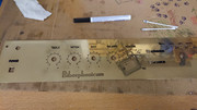
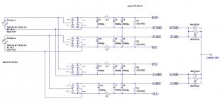
I started out by designing the complete frontplate in InkScape. Since the markings had to fit the already existing holes, cut-outs and knobs, this step required a lot of measuring.
Next I printed the layout on transparent slides (as used for overhead projectors) to verify the alignments.
The transparent foil also helped a lot to mark squares around the individual elements to assist in positioning the laser.
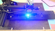
Since my Laser (an Ortur 20Watts) has a limited working area, I could not engrave the whole plate in one go. Instead I had to move and align the laser after every element.
Positioning the laser is always a bit tricky, since the only way to "preview" where the laser will be firing is by outlining the shape with ver low power output.
The Etch Resist
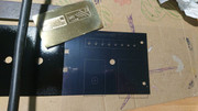
Now it was time to apply an etch resist to the plate. An etch resist is simply some sort of protective layer that keeps the acid away from parts that we do not want to etch. The easiest way to apply etch resist is to simply spray paint the part with acrylic paint. I decided for black paint, as black is the easiest color to laser - it simply absorbs light the most. Nevertheless I had to test several brands of spray paint, as some of them don't adhere to brass very well or are not as "resistant" to acid as expected (some can be easily peeled off or crackle after drying, which would allow the acid to flow in from underneath). I found the spray paints from edding to work really well and also some no-name can from my local store turned out really good.
Great care must be taken to cover really every tiny spot in paint. Don't forget the edges and insides of holes and cut-outs. Every bare spot of metal will be etched away if not properly protected. Little spots can easily be corrected or improved with an edding pen (the ones containing actual lacquer and have that metal ball you need to shake before using it).
For the backside of the plate I simply applied generous amounts of overlapping packaging tape, which also makes for great etch resistant.
Activate Lasssszzzer
Now it was time to engrave my layout into the etch resistant. The laser basically burns away the spray paint and reveals the bare metal where we want to etch. Finding the right settings for the laser was another lengthy process. After some tries I found that the following worked well for me. The settings will very likely be different for another laser and other spray paint:
- Speed 500mm/min
- 90% power
- 2 passes
- 1bit b/w dithering pass-through
Even if you don't happen to have a laser at home, you can still remove the resist by any other means. You could even scratch it off by hand in your own writing or create a stencil. The possibilities are countless from hereon.
 The Etching
Time to actually etch the brass plate. After a few experiments I found that about 10 minutes in Ferric Chloride create the desired effect. Any shorter period will result in lower engravings that cannot be filled with color very well. Longer than 10 mins and you risk to loose details - fragile letters like 'A's and 'e's will become unreadable.
The acid was less problematic to handle than I first anticipated. Just make sure to wear rubber gloves and eye protection. All materials involved should be acid resistant of course. Just don't poke around with metal or organic parts and you'll be safe.
It helps a lot if you warm up the ferric chloride before using it. If you have the possibility, you could also heat the acid bath during the process - for me it worked just fine without.
I kept the solution in motion by gently stirring with a (plastic!) brush over the plate from time to time. Make sure that no bubbles accumulate underneath the plate or in hidden spots.
After the etching time is over you need to neutralize the acid to stop the etching process. I simply purred normal baking soda over the whole plate, which works just great. Keep your neutralizer always at hand if something goes wrong during the process.
Remove Etch Resist
After the etching is done a nasty crust of neutralized ferrit chloride and etch resist has to be removed. Start by carefully washing and brushing the now crusty baking soda of.
To remove the spray paint you will need something stronger though. Universal paint thinner should do the trick to disolve the spray paint. It is quiet a mess though and should be done in a well ventilated area. Also make sure that you have plenty of paper towels at hand, since you will need it in great quantities. Initially I expected the acid etching to be the messy part, but removing the paint was by far the greater hazzle.
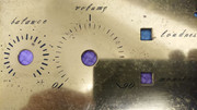
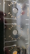
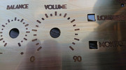
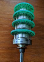
See below a close-up of the etched scale:
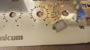
Now is the time to give the brass a good polish. The best polish for brass that I found so far is "Autosol", which I happily recommend.
Filling the Engravings
You can either leave the engravings as they are or take another step and flood fill them with color of your choice. The engraved areas will darken (faster) then the rest over time, which can also look appealing. I decided to fill out all writings and leave the scales as they were.
The filling is quite simple in theory: you pourr plenty of lacquer into the engravings and sand or polish everything plane after the lacquer has dried - leaving only the etched areas filled with paint. The practical application was again not that easy though and required once more several tries. Some of the paint I tested did not dry "hard" enough to be sanded. Other sorts of paints or lacquer attracted dust from the sanded brass parts, which again looked ugly.
The best results were obtained by using the same lacquer edding pen I used before as an etch resist. I painted several times thick layers with the pen and then used plain office paper wrapped around a block of hardwood to "sand" the excess paint off again. Professionals apparently have special filler paint or waxes for this task, but I was happy with the results I was able to generate with household items.
 Finishing Touches
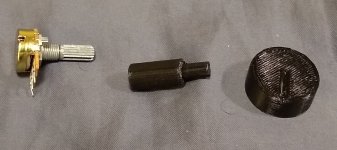
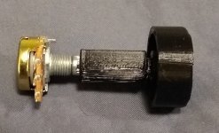
Lastly, I wanted to preserve the shine of the polished brass. It took again many tries (involving Zapon lacquer and the like) until I was recommended "Renaissance Wax". That wax seems to be used a lot by watch makers and was originally developed by the British Museum to preserve all kinds of materials without damage. It is a bit costly, but the smallest can will last you live time and is definately worth it. Just apply a very thin coat of the wax and you will not have to polish the brass for a long time. Even the frequently touched parts, like poti knobs, still look great.
I hope this write-up will be of use or inspiration to someone.
🙂


 (in any order)
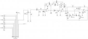


