Hi, lock down has provided me with the opportunity to work on a project I had been keen to explore for some time.
The task was to create an easy to drive "loudspeaker" of sensible efficiency that was flat in power response and FR across a wide horizontal angle that could be used from around 800Hz upwards. The components had to be currently available and with real world prices. Passive circuits were integrated into the design to produce the final result.
I would like to take this opportunity to thank the forum member who converted my circuit designs to gerber files and JLpcb for producing the boards.
The challenge is..."what type of speaker am I"!! For those interested I will post details later. No prizes except smug satisfaction for those who "guess" correctly!
I am posting the plot clues below. Just some supplementary info. The ARTA levels are not calibrated, I use Omnimic for that. Both programmes used the appropriate calibrated mic. The SPL level of 100dB was taken at the surface of the "driver". The distortion plots include the whole system as they are derived from the Omnimic V2 test CD. You will note the 2nd harmonic is around 1.5% at 100dB, (inaudible?) and the 3rd harmonic around .08%. The system includes RME DAC, KT EQPT "pultec" valve EQ, TL audio 5013 parametric, Rane 23s X over and relatively low cost cass AB power amps...EQ was flat for the plots and active crossover set around 1kH/24dB/LR.
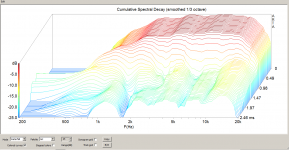
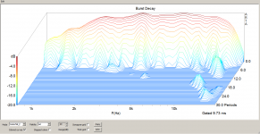
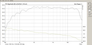
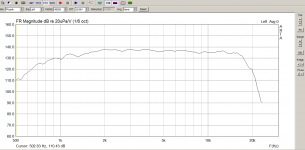
The plot with the FR response and minimum phase is ARTA gated. THE BD and CS plot are derived from ARTA impulse response. The plot of just FR is "in room" at around 1m. The On/Off axis are 0,15,30 and 45H degree plots at 1m. The impedance and phase plot is created by DATs.
So..what type of loudspeaker am I??
The task was to create an easy to drive "loudspeaker" of sensible efficiency that was flat in power response and FR across a wide horizontal angle that could be used from around 800Hz upwards. The components had to be currently available and with real world prices. Passive circuits were integrated into the design to produce the final result.
I would like to take this opportunity to thank the forum member who converted my circuit designs to gerber files and JLpcb for producing the boards.
The challenge is..."what type of speaker am I"!! For those interested I will post details later. No prizes except smug satisfaction for those who "guess" correctly!
I am posting the plot clues below. Just some supplementary info. The ARTA levels are not calibrated, I use Omnimic for that. Both programmes used the appropriate calibrated mic. The SPL level of 100dB was taken at the surface of the "driver". The distortion plots include the whole system as they are derived from the Omnimic V2 test CD. You will note the 2nd harmonic is around 1.5% at 100dB, (inaudible?) and the 3rd harmonic around .08%. The system includes RME DAC, KT EQPT "pultec" valve EQ, TL audio 5013 parametric, Rane 23s X over and relatively low cost cass AB power amps...EQ was flat for the plots and active crossover set around 1kH/24dB/LR.
The plot with the FR response and minimum phase is ARTA gated. THE BD and CS plot are derived from ARTA impulse response. The plot of just FR is "in room" at around 1m. The On/Off axis are 0,15,30 and 45H degree plots at 1m. The impedance and phase plot is created by DATs.
So..what type of loudspeaker am I??
Attachments
-
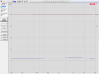 Impedance + Phase.png20.4 KB · Views: 460
 -
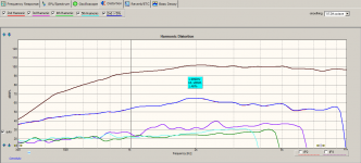 Distortion Plot. Whole system, 2nd Order harmonic, 100dB.png32.7 KB · Views: 122
 -
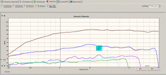 Distortion Plot. Whole system, 3rd Order harmonic, 100dB.png33 KB · Views: 127
 -
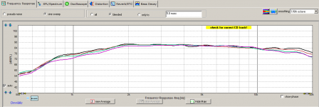 0,15,30,45 Deg.png27.9 KB · Views: 141
 -
 Cumulative Spectrum from Impulse.png112.4 KB · Views: 453
 -
 Burst Decay from Impulse.png85.6 KB · Views: 549
 -
 Gated +Phase.png26.6 KB · Views: 459
 -
 In Room FR.png25.8 KB · Views: 457
Last edited:
What am I
Indeed, implementing a passive crossover at either end of the frequency spectrum will be a doddle..it's 6 ohms all the way!!
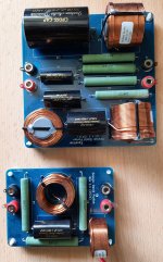
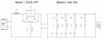
Some have got very close, but I'm not giving it away yet!! But I am posting the circuit layout and pics of the final boards to add to the jigsaw!
I have been involved at the design end of audio for 40 odd years and have always sought innovative solutions. I prefer measurement and listening first and subjective assumptions and popular beliefs never! I am not swayed by brand name or cost because science doesn't care what name is on the front or how many $/£0000's there are...
I also accept perfection is a pointless goal because somewhere there will always have to be compromise. The trick is putting the compromises where they are least audible? My intention with this design was to enable "it" to be integrated into two way system design. A better option than three way and not as perfect as the unachievable one way!
So yes, as observed the BD is less than perfect above 10khz. But as we know there is very little information in this octave..and I'm 67!! You can simply add a "super tweeter" which was tried both with passive and active crossover..tweeters tried were the Visaton tl16..utterly flat to 30Khz and much, much cheaper than its competition..Bob Crites CT125, Beyma CP25's, etc..but in all cases, at least in my listening room, the additional source, even with time delay adjustments was more "obvious" than all the sound from 800Hz upwards coming from one source...
Indeed, implementing a passive crossover at either end of the frequency spectrum will be a doddle..it's 6 ohms all the way!!
Some have got very close, but I'm not giving it away yet!! But I am posting the circuit layout and pics of the final boards to add to the jigsaw!
I have been involved at the design end of audio for 40 odd years and have always sought innovative solutions. I prefer measurement and listening first and subjective assumptions and popular beliefs never! I am not swayed by brand name or cost because science doesn't care what name is on the front or how many $/£0000's there are...
I also accept perfection is a pointless goal because somewhere there will always have to be compromise. The trick is putting the compromises where they are least audible? My intention with this design was to enable "it" to be integrated into two way system design. A better option than three way and not as perfect as the unachievable one way!
So yes, as observed the BD is less than perfect above 10khz. But as we know there is very little information in this octave..and I'm 67!! You can simply add a "super tweeter" which was tried both with passive and active crossover..tweeters tried were the Visaton tl16..utterly flat to 30Khz and much, much cheaper than its competition..Bob Crites CT125, Beyma CP25's, etc..but in all cases, at least in my listening room, the additional source, even with time delay adjustments was more "obvious" than all the sound from 800Hz upwards coming from one source...
Attachments
What am I
Well that would give it away of course!
The point of the challenge I guess is what you have in a sense suggested...a loudspeaker has measurable properties. We have come to recognize many by their response and impedance, such as the classic ribbon flat impedance and often flat response.
A nod here to the software developers who have provided us with programmes to dig deeper into loudspeaker behaviour with gated response, impulse and consequently burst decay and cumulative spectrum, polar response, circuit simulations, etc...opportunity here to thank them for there great work, couldn't have done it without them!
I am a designer and have been for 40 years, I put scientific method and listening before subjectivism, brand names and commonly held and often misguided beliefs.
It was my conjecture that a loudspeaker is just part of a circuit. Making the load, in this case, virtually a pure resistance must bring benefits in terms of consistent damping and an easy load for those who may like "esoteric" valve amps. Also a gift for those who like passive crossovers!
Passive EQ would be implemented to provide another important performance parameter, substantially flat frequency response in the bandwidth of interest and with consistent results on and off axis to provide even power distribution.
The EQ circuit must work with the impedance leveler as one circuit to provide both performance goals.
In other words it works as a single entity. There would be little, or indeed no value in just publishing what in effect were the Thiele Small parameters of the driver by itself which would clearly defeat the purpose of the whole exercise? The "total" performance, as shown in the plots, is a result of all the components working together...
looks like any speaker that has a crossover and eq. what do we have to guess ? since all the attributes are gone. ! it could be any speaker. whats the point?
how can people say it looks liek a heil ? why ?? please. since it does not make sence , i can make multiple speakers that have the same distortion patern.. impedance could be any since there is a crossover in place. so whats the deal WHERE are the guesses based on ?
couyld be any planar magnetic. AMT, RIBBON, PLANAR, RUBANOIDE (depending on the coil design)
Last edited:
Sorry to mislead. There is a single LP choke on the eq board..the first one set at 8khz for those that want to use a super tweeter. You will see it is shorted out in the circuit diagram...there is no passive crossover component in circuit in the plots. As per the original post an active 4th order LR is applied at around 800Hz.
Otherwise it is purely a passive eq circuit and impedance leveler circuit (RCL +zobel)..I repeat, there are no passive crossover components in circuit to produce the plot results.
Otherwise it is purely a passive eq circuit and impedance leveler circuit (RCL +zobel)..I repeat, there are no passive crossover components in circuit to produce the plot results.
Last edited:
- Home
- Loudspeakers
- Planars & Exotics
- What am I?