Translated From Mr Makoto Ohashi's forum
World Premiere - Western Electric WE300B/2021 Lot REPORT #1
In 2006, the Western Electric 300B was discontinued without any notice although manufacturing announcements were repeated on the WE homepage,
no one even saw the actual product in the United States, and gradually the people concerned said that it would be difficult to revive even in the meantime,
and it had been 15 years since the production was discontinued.
That is the complete announcement. I contacted the site immediately and confirmed that it was true, it seemed to be true this time. So I immediately placed an order.
The reason is electrical measurement and sound quality confirmation. For that purpose, 2 valves are not enough, so I decided to purchase a matched quad (4 valves).
The local price is US $ 3099. If you add tariffs and shipping costs, it's a lot of money, but that's not the case.
When it comes to the revival of the original Western, I have to get it anyway ... I felt like that sense of mission.
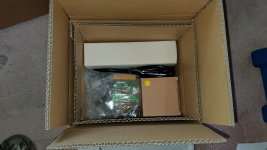
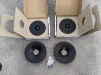
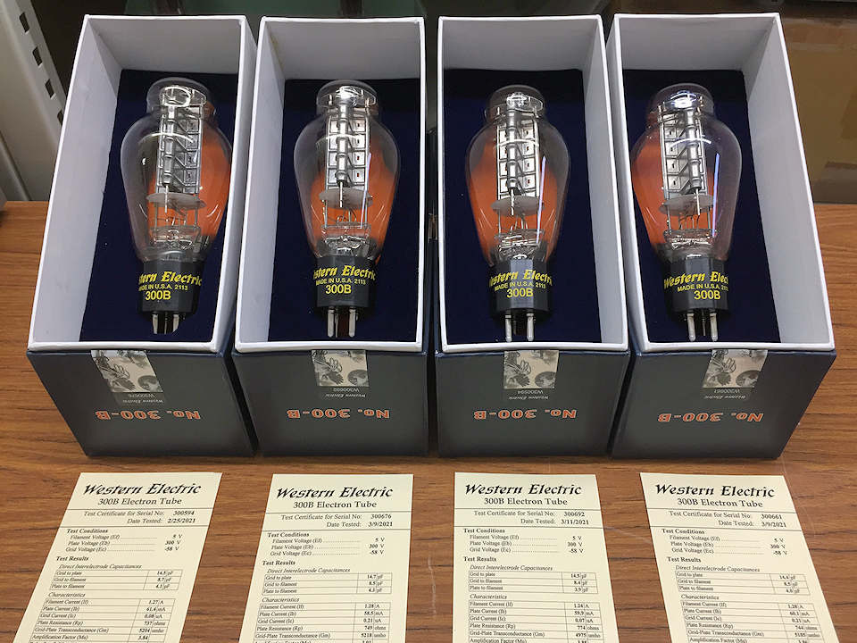
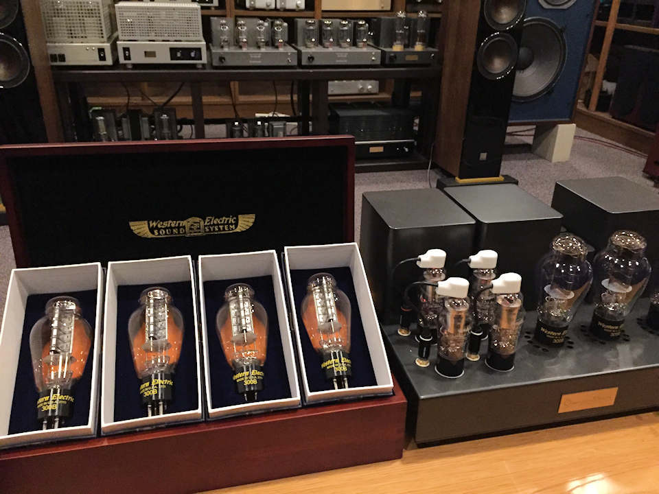
What appeared in front of me after unpacking it ...
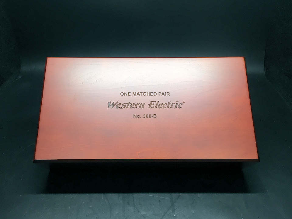
There is no different from 15 years ago. This is the best of the original Western Electric.

There is no different from 15 years ago. This is the best of the original Western Electric.
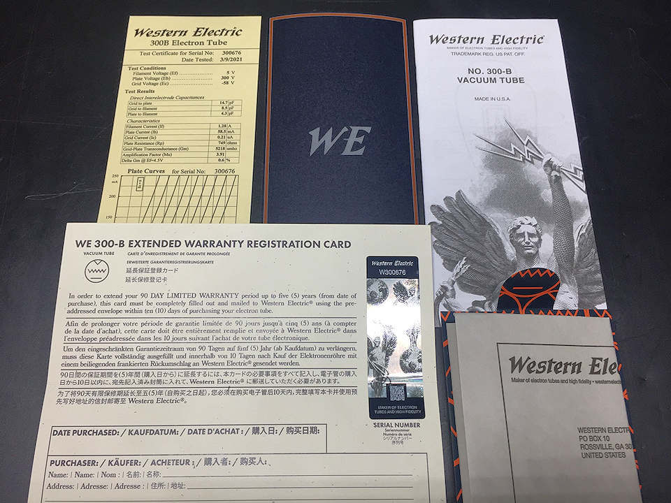
In the box, the instruction manual, measurement data with serial number, and warranty registration card are stored as they were in 2006.
The most important measurement data sheet. The method of measuring the Ip value at Ep = 300V and EG = -58V is the same as at that time.
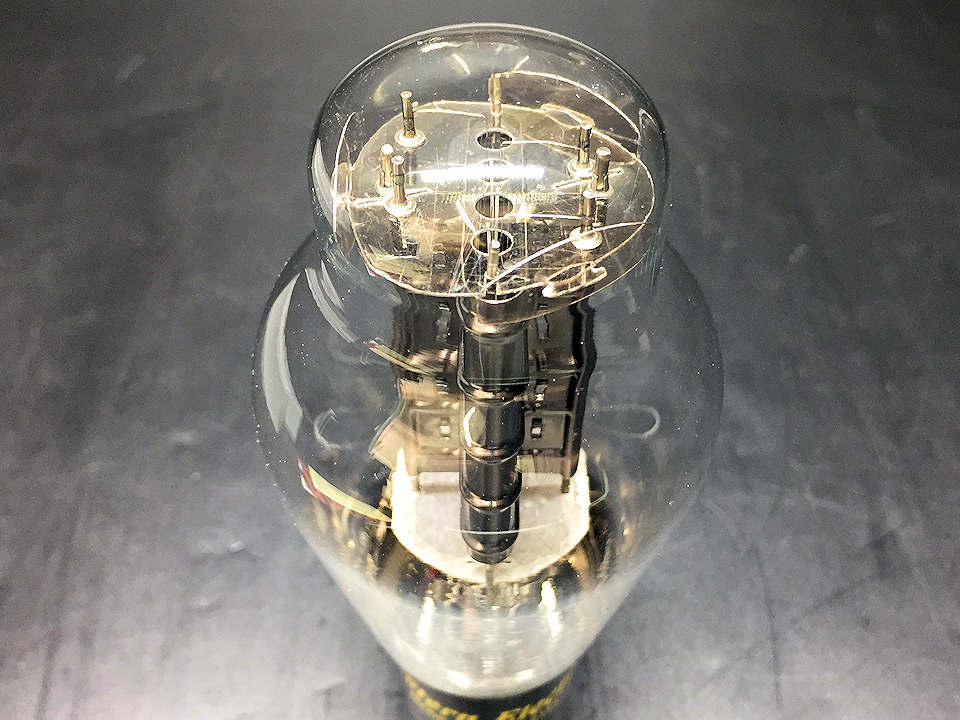
Each part in the valve has not been changed from the original. The thinness of the glass remains the same as it was at that time.
The pitch of the sound when the glass clicked with the index finger is also unique to the WE300B.

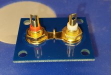
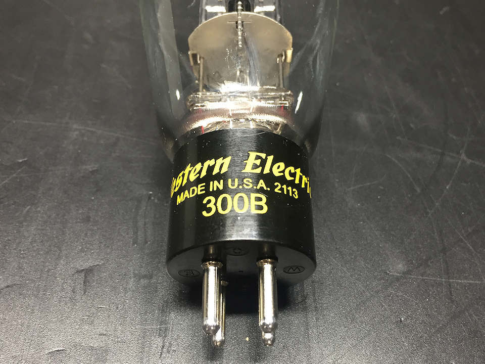
Print of the base part. The miracle of date code 2113 (first quarter of 2021) will be handed down forever.
The appearance of the rice ball-shaped mica, including the filament hook shape, has not changed at all.

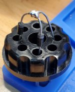
This is the serial number stamped on the base. The new lot starts at 3.
It can be said that the product is complete only when these three numbers, the outer box, the data sheet, and the engraved base, are complete.
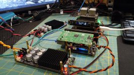
So far, it's perfect, it's better than expected. But my biggest purpose today is from here. How does the electrical characteristics compare to the conventional original WE300B?
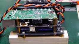
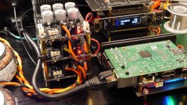
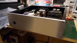
…about it. For that purpose, a helper was called in a hurry. We decided to have Mr. S, who is asking us to assemble our amplifier,
come to the showroom and perform precise measurements. Is the objectivity of the attached data sheet guaranteed?
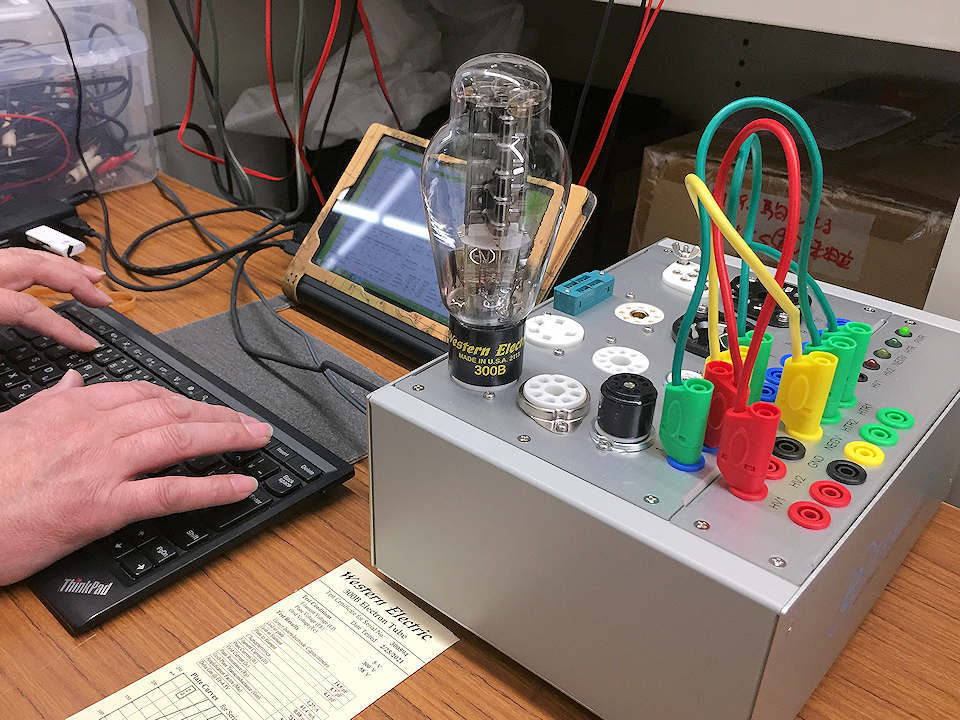
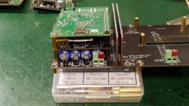
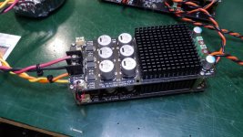
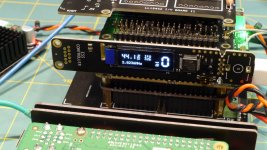
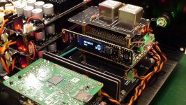
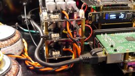
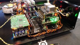
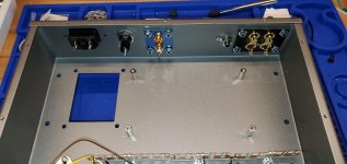
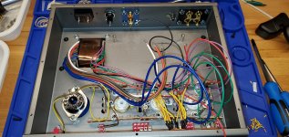
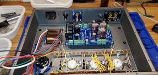
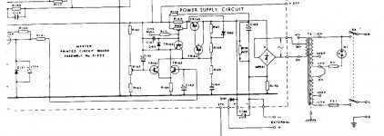
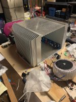
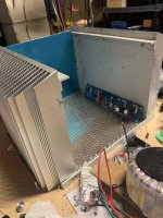
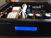
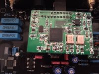
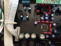
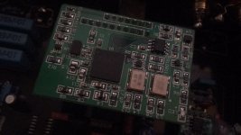
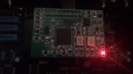
This is a device that records the dynamic characteristics of a vacuum tube by swinging the plate voltage and grid bias.
All control and data management is done on the computer.
Is it easy to understand the device for measuring the Ep-Ip curve that is often found on vacuum tube data sheets?
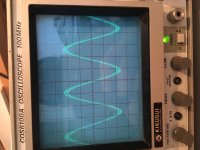
Is the wonderful Ep-Ip characteristic attached to the reissue WE300B ?
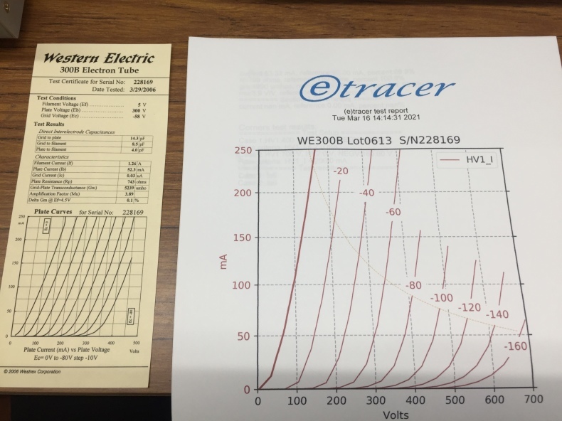
The data sheet attached to the product is on the left. The data on the right is the data measured in kind today.
First of all, I tried to collect data on individuals in the first quarter of 2006.
Although there was a 2-3% difference that seemed to be environment-dependent when compared,
the same difference was observed at almost all points, indicating that the reliability of the measurement results is extremely high.
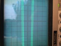
Finally, when I take the data of this lot ...
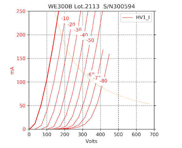
Plate current: 56.93 mA, internal resistance: 800 Ω, transconductance: 4891 μm hos, μ: 3.9 V / V

Plate current: 56.41 mA, internal resistance: 820 Ω, transconductance: 4753 μm hos, μ: 3.9 V / V
Data log was detected. It is a unique value to the head family, which is completely impeccable.
First of all, I was very satisfied with the fact that the electrically incorrect one was reprinted.
Let's check the sound quality before checking whether it can be said that the price is about twice as high as it was in 2006.
Change the place to the listening room and burn in 300B first. After getting used to it until tomorrow morning,
I plan to take the time to listen to the comparison. Please stage tuned the second report (listening)!


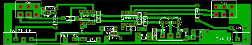
![2021-05-11 09_10_04-LTspice XVII - [Opamp THD Test.asc].png](/community/data/attachments/873/873952-ab7e6cec6afe14593127d30dc40f525c.jpg?hash=q35s7Gr-FF)