I have a TU-8200R that I have put together with kind assistance from Victor, who has been awesome to deal with. Victor pointed out that at p.19 of the manual there is chart with reference voltages that can be checked. I am careful and this is new to me, so I want to be sure I know what to do.
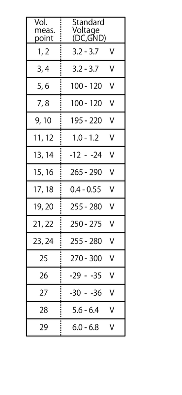
I found the points in the circuit board, and see, for example, that the first row says 1,2 3.2-3.7v. Is this DC or AC? (I presume DC but am not sure). Do I measure voltage between points 1 and 2, or do I measure each of them to ground?
Any clarification on this would be appreciated. The amp appears to be working well, and sounds beautiful.
TIA.
It's true that the instructions are ambiguous, and should be improved to be more clear.
After all, kits like this are mostly assembled by novices unfamiliar with such details.
However, odds are that your interpretation is correct, DC voltage between points 1 and 2.
After all, kits like this are mostly assembled by novices unfamiliar with such details.
However, odds are that your interpretation is correct, DC voltage between points 1 and 2.
Last edited:
Then I would recommend that you revise that chart.
For a beginner, it is just too confusing.
Each test point to ground should be on a separate line.
Test Point #........Value (DC Volts to ground)
1........................3.2 to 3.7
2........................3.2 to 3.7
3........................3.2 to 3.7
4........................3.2 to 3.7
etc.
For a beginner, it is just too confusing.
Each test point to ground should be on a separate line.
Test Point #........Value (DC Volts to ground)
1........................3.2 to 3.7
2........................3.2 to 3.7
3........................3.2 to 3.7
4........................3.2 to 3.7
etc.
The chart is good. When the test point are on the same line, they refer to the same point on the left and right channels. The closer they are, the more the channels are in balance.
I have only one comment on point# 28. 5.6V heater voltage is too low, it needs to be between 5.8 and 6.4 Volts.
I have only one comment on point# 28. 5.6V heater voltage is too low, it needs to be between 5.8 and 6.4 Volts.
I have just talked to MK
The chart is very clear to him now
No issue to understand
It is clear now. Thank you Victor. (A personal phone call to help on a long weekend!) What Victor told me is that you check EACH point to ground. So point 1 to ground should be 3.2-3.7v DC. Point 2 to ground should be the same. Each point is together in the chart to deal with right and left channels to compare them. Testing requires power on, tubes inserted, and cover off, so be careful.
My instructions look slightly different
 which might have been some of the need for clarification.
I checked all my values and they were within spec. A couple were a few percentages bigher, perhaps due to my wall voltage or maybe the Lundahls?
I have never done this before, and though I have skill, I lack experience. Victor has been helpful, patient and professional even with someone like me. I highly recommend dealing with him.