Hello all,
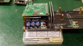
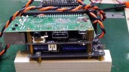
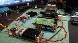
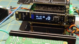
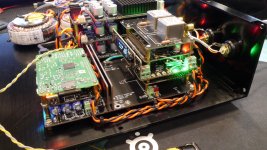
After enjoying a couple of years with Ian Canada's DAC stack, I thought I would build version 2. This would encompass using some of his new boards and use the StationPi as the platform. This is not a full evaluation of the sound, but rather a peek at some of the stages of my build using the new parts. I'm still listening to it on my bench, and have a couple more tweaks to finish it up.
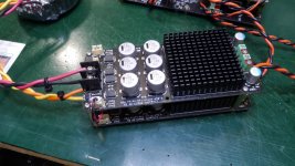
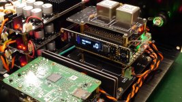
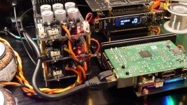
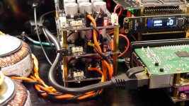
A few notable differences from my first version are the addition of the new ConditionerPi, the FifoPi Q3, the StationPi, and the use of Ian's new LinearPI PSUs. To add to the versatility of the streamer, I also added the ReceiverPi for additional inputs - primarily Toslink. Oh, and of course the addition of a transformer output stage. Using a transformer output stage is a first for me, so will be interesting to compare the sound to my opamp output stage of my original.
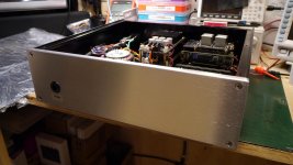
Using the StationPi, the layout is less spread-out and more compact. The stackable PSU really helped gain back some chassis space too. I used 3 of them for the necessary 5.0 and 3.3v. Still had to use 2 xformers though, to get enough independent secondary windings. In addition, I did not need the +-15V PSU for the opamps of the Std I/V stage, so that helped with space as well. A cool feature of the LinearPis is they can be strapped for Master/Slave control. The external front-panel switch controls them all using this feature.
I put it all in the temporary chassis, so I could easily move it into my listening room and compare the sound using roon. The case is not up to my usual standards, but it's workable for the foreseeable future. Enjoy the pictures.
Note: Ian has some other new goodies supposedly to be revealed later this week.
After enjoying a couple of years with Ian Canada's DAC stack, I thought I would build version 2. This would encompass using some of his new boards and use the StationPi as the platform. This is not a full evaluation of the sound, but rather a peek at some of the stages of my build using the new parts. I'm still listening to it on my bench, and have a couple more tweaks to finish it up.
A few notable differences from my first version are the addition of the new ConditionerPi, the FifoPi Q3, the StationPi, and the use of Ian's new LinearPI PSUs. To add to the versatility of the streamer, I also added the ReceiverPi for additional inputs - primarily Toslink. Oh, and of course the addition of a transformer output stage. Using a transformer output stage is a first for me, so will be interesting to compare the sound to my opamp output stage of my original.
Using the StationPi, the layout is less spread-out and more compact. The stackable PSU really helped gain back some chassis space too. I used 3 of them for the necessary 5.0 and 3.3v. Still had to use 2 xformers though, to get enough independent secondary windings. In addition, I did not need the +-15V PSU for the opamps of the Std I/V stage, so that helped with space as well. A cool feature of the LinearPis is they can be strapped for Master/Slave control. The external front-panel switch controls them all using this feature.
I put it all in the temporary chassis, so I could easily move it into my listening room and compare the sound using roon. The case is not up to my usual standards, but it's workable for the foreseeable future. Enjoy the pictures.
Note: Ian has some other new goodies supposedly to be revealed later this week.
Attachments
-
 P1020587.jpg980 KB · Views: 1,907
 -
 P1020589.jpg945.9 KB · Views: 2,038
 -
 P1020593.jpg968.1 KB · Views: 1,795
 -
 P1020600.jpg1,005.1 KB · Views: 2,492
 -
 P1020601.jpg928.3 KB · Views: 1,987
 -
 P1020615.jpg991.7 KB · Views: 1,605
 -
 P1020617.jpg1,004.1 KB · Views: 1,565
 -
 P1020619.jpg982.7 KB · Views: 1,580
 -
 P1020623.jpg1,014 KB · Views: 1,625
 -
 P1020626.jpg829.5 KB · Views: 1,760
@redjr
Very well built system. You did good job. Looks very nice. Congratulations!
I'm now working on the StationPi Pro (SMT finished) project. It will bring more powerful features to the system and the mounting screws will be compatible with StantionPi DIY.
Just hope having more fun with your projects.
Regards,
Ian
Nice build redjr. Good to see someone else using the Chinese output trafos. I've built 2 Ian systems aswell, one for my brother. He has a serious commercial system and he prefers these trafos over the IVSTD. And it saves a psu which saves space for other goodies!
Good work sir.
Good work sir.
Thanks jimk. The Chinese ones will have to do for now. I wish I could afford the bisesik output xformers. They are highly recommended and Ian likes them as well. I've been listening to my upgraded DAC this afternoon - just casually. So far there's nothing not to like. Same quality sound! I suspect the sonic differences will be subtle. Due to the influence of the ConditionerPi and the xformer output stage primarily. Everything else is fairly similar to the original. Since I use roon as my whole-house digital distribution system, it's very easy to set up two sources (end-points), link them together and feed them into two separate analog inputs on my pre and then do an A-B comparison simply by changing inputs. Level matching may be tricky due to my original being STD I/V opamp output stage, and this one being transformer. Well see.Nice build redjr. Good to see someone else using the Chinese output trafos. I've built 2 Ian systems aswell, one for my brother. He has a serious commercial system and he prefers these trafos over the IVSTD. And it saves a psu which saves space for other goodies!
Good work sir.
Red,
Beautiful and clean build! I was wondering, could you explain how you went about earthing everything? I have an Allo USBridge Signature and an Allo Shanti LPS. The Shanti has the IEC input ground wire attached to the chassis and an external grounding terminal. The USBridge Signature also is grounded to the chassis and the chassis also contains a grounding terminal. Allo recommends attaching both terminals together. This is easy enough for a beginner like me but I don't know what to do if I put everything together in one chassis like you've done.
My chassis will include the Shanti LPS without the enclosure, the USBridge Signature without the enclosure, 3 of the UcConditioner and 2 LinearPi being fed from one transformer. The UcConditioners have an earth terminal and I'm not sure about the LinearPi. I just want to understand how to ground everything properly and not create ground loops. Can you give me some pointers in a way where other beginners like myself can understand? This forum is a great resource!
Hi WuBai,
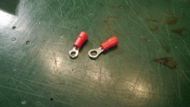
What I typically do is first ground the IEC to the chassis with a short piece of GREEN ~18AWG wire. I generally use a 4mm bolt by about 8-10mm long as a grounding post from the bottom of my chassis. The length will be determined by the thickness of your chassis and how many grounding wires you need. Be sure and sand off any paint or anodizing from around the hole in your chassis. Then use an external toothed washer to make a solid connection of the 4mm bolt to the chassis with a nut. You should be left with about a 4mm extension of the bolt to add additional grounding cable/lugs from your circuitry. I always use the round crimp connector and solder the cable to the connector first. Using the round connector ensures that it will not come off the grounding bolt. See picture below. These are useful to keep in your shop. You can get a variety-pack from Amazon here.
For this project, I used Ian's suggestion and ran a grounding cable from the StationPi (as noted on the PCB) to the grounding bolt near the IEC as mentioned above. Any other PCBs that have a specific ground point, run a separate cable back to the grounding bolt. This is considered a 'star' grounding scheme. Most DIY'ers like to use it, some are not so sure.") Personally, I ALWAYS use green cable for earth ground. It's a standard color used in the US for earth ground. And you can easily, visually identify that's it the ground!
Personally, I ALWAYS use green cable for earth ground. It's a standard color used in the US for earth ground. And you can easily, visually identify that's it the ground!
I'm not familiar with the Shanti PSU, but you will want to run an earth ground cable back to the grounding bolt, unless the ground wire from the IEC goes directly to the Shanti PCB connector. You will also want to run a cable from the USBSignature to the grounding bolt since it has an earth ground connector.
For this particular build of mine, I did not ground the LinearPis. Both of my Ian Jin DAC stacks have been working without any hint of hum, or ground loop noise. (That I can hear.)
Hope this helps. Good luck with your build.
Rick
What I typically do is first ground the IEC to the chassis with a short piece of GREEN ~18AWG wire. I generally use a 4mm bolt by about 8-10mm long as a grounding post from the bottom of my chassis. The length will be determined by the thickness of your chassis and how many grounding wires you need. Be sure and sand off any paint or anodizing from around the hole in your chassis. Then use an external toothed washer to make a solid connection of the 4mm bolt to the chassis with a nut. You should be left with about a 4mm extension of the bolt to add additional grounding cable/lugs from your circuitry. I always use the round crimp connector and solder the cable to the connector first. Using the round connector ensures that it will not come off the grounding bolt. See picture below. These are useful to keep in your shop. You can get a variety-pack from Amazon here.
For this project, I used Ian's suggestion and ran a grounding cable from the StationPi (as noted on the PCB) to the grounding bolt near the IEC as mentioned above. Any other PCBs that have a specific ground point, run a separate cable back to the grounding bolt. This is considered a 'star' grounding scheme. Most DIY'ers like to use it, some are not so sure.
Personally, I ALWAYS use green cable for earth ground. It's a standard color used in the US for earth ground. And you can easily, visually identify that's it the ground!I'm not familiar with the Shanti PSU, but you will want to run an earth ground cable back to the grounding bolt, unless the ground wire from the IEC goes directly to the Shanti PCB connector. You will also want to run a cable from the USBSignature to the grounding bolt since it has an earth ground connector.
For this particular build of mine, I did not ground the LinearPis. Both of my Ian Jin DAC stacks have been working without any hint of hum, or ground loop noise. (That I can hear.)
Hope this helps. Good luck with your build.
Rick
Attachments
- Home
- Source & Line
- Digital Line Level
- My Version 2 of the Ian Canada DAC Stack