Hi all,
I have a Gould J3B signal generator from the late 70s that I want to repair and restore as it has some very useful capabilities for audio work. It arrived looking good on the outside and grim on the inside and I can't get it past the "sort of half repaired" stage and would be grateful for some help chasing down the issues.
It has a Wein bridge oscillator in a shielded box and a power amplifier that can drive very low impedance loads directly, which makes woofer testing easy, as well as a 600 ohm balanced output transformer, for testing pro audio gear, as well as a square wave and auxiliary outputs for sync. In short it's perfect for what I want and there doesn't seem to be new equivalent available and so I'm quite keen to fix it.
Please find the service manual and schematic here: http://bee.mif.pg.gda.pl/ciasteczkowypotwor/Gould/gould.__j3b._._service_and_operating..pdf
It had a blown fuse and the power supply needed repair. I replaced the blown components and all the small capacitors as they were reading high and leaky.
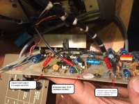
The PCB for this is shared with the power amplifier and it appears that the power amplifier had been repaired at some point in the past and mismatched transistors used in the final outputs ( TR105&TR106). The service manual specifies 2N6179 & 2N6181 whereas this one has a BD237 & BD131 fitted. As I understand these parts are not equivalent and I have ordered MJE172/182 transistors as the closest I could find that is available new.
TR104 and TR108 were damaged and were replaced with NOS BC239 and BCY70 transistors.
The PCB then powered up and the test voltages were within spec. I set up the bias current through TR105&TR106 as per 5.6 (i) in the service manual and couldn't get the current quite high enough, even by turning the pot the whole way. In fact the pot didn't seem to have any sort of linear effect, it just seemed that at some point some bias current (~6 ma) would flow. I left this as it was, although the level specified was 18-30ma, and soldered the various wires ( to and from the oscillator as well as power, meter, outputs and grounds ) and with an ammeter between the test points I powered it up.
The bias shot up and the fuse blew again. After much swearing I checked everything over and powered it up again to find that now, for some reason, the biasing worked as per the manual and that everything seemed fine...
The problem is that now, when the output is turned up the output from the amplifier and the Wein bridge oscillator distort by oscillating like mad. This does not happen when the oscillator is isolated from the amplifier board.
Could the wrong output transistors cause this or have I damaged the oscillator somehow?
I have a Gould J3B signal generator from the late 70s that I want to repair and restore as it has some very useful capabilities for audio work. It arrived looking good on the outside and grim on the inside and I can't get it past the "sort of half repaired" stage and would be grateful for some help chasing down the issues.
It has a Wein bridge oscillator in a shielded box and a power amplifier that can drive very low impedance loads directly, which makes woofer testing easy, as well as a 600 ohm balanced output transformer, for testing pro audio gear, as well as a square wave and auxiliary outputs for sync. In short it's perfect for what I want and there doesn't seem to be new equivalent available and so I'm quite keen to fix it.
Please find the service manual and schematic here: http://bee.mif.pg.gda.pl/ciasteczkowypotwor/Gould/gould.__j3b._._service_and_operating..pdf
It had a blown fuse and the power supply needed repair. I replaced the blown components and all the small capacitors as they were reading high and leaky.
The PCB for this is shared with the power amplifier and it appears that the power amplifier had been repaired at some point in the past and mismatched transistors used in the final outputs ( TR105&TR106). The service manual specifies 2N6179 & 2N6181 whereas this one has a BD237 & BD131 fitted. As I understand these parts are not equivalent and I have ordered MJE172/182 transistors as the closest I could find that is available new.
TR104 and TR108 were damaged and were replaced with NOS BC239 and BCY70 transistors.
The PCB then powered up and the test voltages were within spec. I set up the bias current through TR105&TR106 as per 5.6 (i) in the service manual and couldn't get the current quite high enough, even by turning the pot the whole way. In fact the pot didn't seem to have any sort of linear effect, it just seemed that at some point some bias current (~6 ma) would flow. I left this as it was, although the level specified was 18-30ma, and soldered the various wires ( to and from the oscillator as well as power, meter, outputs and grounds ) and with an ammeter between the test points I powered it up.
The bias shot up and the fuse blew again. After much swearing I checked everything over and powered it up again to find that now, for some reason, the biasing worked as per the manual and that everything seemed fine...
The problem is that now, when the output is turned up the output from the amplifier and the Wein bridge oscillator distort by oscillating like mad. This does not happen when the oscillator is isolated from the amplifier board.
Could the wrong output transistors cause this or have I damaged the oscillator somehow?
Attachments
Last edited:
Hi,
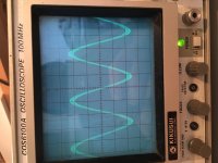
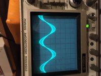
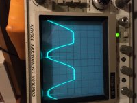
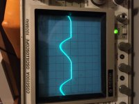
The sine wave in the first photo appears "thick." Is this a high frequency oscillation riding on the oscillator output? Is this the distortion you mention? If the output amplitude is set to 0 via the level pot (R10) and the oscillator is measured at the top of R10, is the oscillator then clean?
Would you provide details about the test points being probed in your photos? e.g. What points in schematic, volts/div and time/div. BTW, I also advise using x10 scope probes to minimize load capacitance when probing internal test signals.
Good luck!
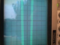
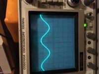
It is, the second photo is that of the "thick" sine wave in the first photo zoomed in using the scope.
The test point is as advised in the service manual and is clean and showing the right amplitude ( about 8V pk-pk) both when the power amp is disconnected ( i.e. just the power wire connected ) or if R10 isn't turned up high enough to cause the oscillation.
Thanks for your help, I've learned a lot fiddling with this thing, these pre-IC era circuits are fun to work on.
Attachments
So if I'm interpreting correctly, the signal behaves reasonably until sudden onset of higher frequency oscillation.
To take a super wild guess with scant evidence, I'd suspect power supply bypass defect and would look for supply misbehavior at onset of oscillation.
Assuming your scope is dual channel, I suggest the putting oscillator test point on channel 1 and using channel 2 to poke around for sudden appearance of the spurious oscillation on the supply rail. Supply ripple should be only few mV, I think. If ripple seems suspicious, failed cap might be the culprit.
If supply looks ok, poke elsewhere for clues and keep us posted. I can suggest additional experiments if problem not found.
Good luck.
Thanks for your suggestions, I shall probe the power supply rail and see if there is an overload.
Your surmise is correct but I think that increasing the output increases the oscillation riding on the fundamental, becoming very obvious at full output. I think I see the line thickening as I turn it up.
I have completely recapped the entire unit, I was bored and it's a lockdown, so I don't think it's the capacitors.
Attachments
Also, something that might be relevant.
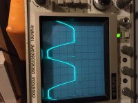
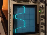
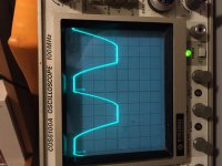
In the service manual it says that when the 'scope is connected to the test point and power applied, the oscillator should build up, die down and then build up again.
It does not do this, on the scope DC builds up in one direction and then in the other. then a very clipped sinewave is produced which seems to be at rail voltage peak to peak.
This clipped sine wave, almost a square wave, has a nasty spike at the top of the leading edge.
I'll try and get a photo of it with the digital 'scope.
I wonder if TR165 might have failed as well. It's hard to imagine that TR164 would fail with TR165 still surviving. But if TR165 collector was open, TR164 would have to carry all current and might fail by excessive dissipation.
Do you happen to have a current-limited bench power supply that could supply +37V during debug?
Do you happen to have a current-limited bench power supply that could supply +37V during debug?
if the pass transistors in the supply ar popping and you did not do something obvious then the zener current limiter may have failed.
I would do the following as an initial troubleshooting step-
1) Open the current sens link on the amp and the corresponding resistor in the positive rail to prevent big currents going there.
2) Ensure that the necessary heatsinking for the pass transistor in the supply is in place.
3) Check the current limit Zener D162 is working right or replace it with a known good Zener.
4) make sure all the caps are in correctly. A backwards Electrolytic can ruin your day. They have ruined many of mine.
5) If all OK give it a quick blast to charge the supply and see if the primary caps go to 40V or 50V and that the regulated voltage is around 37. You don't leave the power on for more than a moment. if the 37 does not come up or it sags to zero instantly you have a short on the regulated supply. You can also check with an Ohmmeter back in step 4. You should see K Ohms across the supply.
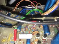
When you have the supply working your oscillator issue may be the AGC. I suspect there is a light bulb in the feedback but I could not find it in the schematic. If there is it may be open.
I would do the following as an initial troubleshooting step-
1) Open the current sens link on the amp and the corresponding resistor in the positive rail to prevent big currents going there.
2) Ensure that the necessary heatsinking for the pass transistor in the supply is in place.
3) Check the current limit Zener D162 is working right or replace it with a known good Zener.
4) make sure all the caps are in correctly. A backwards Electrolytic can ruin your day. They have ruined many of mine.
5) If all OK give it a quick blast to charge the supply and see if the primary caps go to 40V or 50V and that the regulated voltage is around 37. You don't leave the power on for more than a moment. if the 37 does not come up or it sags to zero instantly you have a short on the regulated supply. You can also check with an Ohmmeter back in step 4. You should see K Ohms across the supply.
When you have the supply working your oscillator issue may be the AGC. I suspect there is a light bulb in the feedback but I could not find it in the schematic. If there is it may be open.
Also, something that might be relevant.
In the service manual it says that when the 'scope is connected to the test point and power applied, the oscillator should build up, die down and then build up again.
It does not do this, on the scope DC builds up in one direction and then in the other. then a very clipped sinewave is produced which seems to be at rail voltage peak to peak.
This clipped sine wave, almost a square wave, has a nasty spike at the top of the leading edge.
I'll try and get a photo of it with the digital 'scope.
Good suggestions from Demian.
I believe the manual is trying to describe the "bounce" in amplitude of the sine wave as the thermistor level control settles to equilibrium. This portion of the instrument was working earlier as demonstrated in your first photo. I suspect that the most crucial thermistor (R44) is still intact, as I doubt the circuit would oscillate if it were open. Were you perhaps experimenting with the setting of R34 in pursuit of observing this phenomenon? If this pot setting is too high there will be clipping of the sine wave. BTW, the other thermistor is meant to compensate for internal temperature rise inside the instrument; its role is minor and the instrument could still work in its absence. R44 is responsible for amplitude stabilization.
I suggest a divide and conquer approach: I’d set R10 level to 0, perhaps even disabling the amplifier as Demiam suggests. Once you have the power supply again working and R10 still at 0, try adjusting R34 to get the specified oscillator amplitude at the test point. If the oscillator works and is absent spurious oscillation, assume it’s OK and install its cover to ensure it's well shielded.
Assuming misbehavior returns as R10 is advanced, I suggest disconnecting the oscillator at the top of R10 and instead driving R10 from an external generator. The amplifier can then be tested for problems without having to suspect unknown coupling back to the internal oscillator. I bet the problem is local to the amplifier.
Last edited:
Thank you very much for taking the time to look at this all and make your suggestions, it is very much appreciated.
@ BSST,
Unfortunately I don't have a power supply capable of more than 30 volts, I have two old Farnell 0-30V power supplies, a L30B and a E30/2. Given that they are different models, I am not sure whether it would be safe to connect them in series, as I understand is possible with certain types of identical power supply.
I have a sort of plan to link two primaries of a 18V AC transformer and build a circuit with an LM317 to give it's maximum of 36 volts but am still researching this as it seems that there is a reasonable chance of blowing that up too by dint of operating on it's limits.
I shall try your suggestions and report back.")
@1audio,
Thank you Demian, very kind. I shall check the points you suggest and report back.
Thanks again chaps, I would be utterly stuck without you.
@ BSST,
Unfortunately I don't have a power supply capable of more than 30 volts, I have two old Farnell 0-30V power supplies, a L30B and a E30/2. Given that they are different models, I am not sure whether it would be safe to connect them in series, as I understand is possible with certain types of identical power supply.
I have a sort of plan to link two primaries of a 18V AC transformer and build a circuit with an LM317 to give it's maximum of 36 volts but am still researching this as it seems that there is a reasonable chance of blowing that up too by dint of operating on it's limits.
I shall try your suggestions and report back.
@1audio,
Thank you Demian, very kind. I shall check the points you suggest and report back.
Thanks again chaps, I would be utterly stuck without you.
if the pass transistors in the supply ar popping and you did not do something obvious then the zener current limiter may have failed.
I would do the following as an initial troubleshooting step-
1) Open the current sens link on the amp and the corresponding resistor in the positive rail to prevent big currents going there.
2) Ensure that the necessary heatsinking for the pass transistor in the supply is in place.
3) Check the current limit Zener D162 is working right or replace it with a known good Zener.
4) make sure all the caps are in correctly. A backwards Electrolytic can ruin your day. They have ruined many of mine.
5) If all OK give it a quick blast to charge the supply and see if the primary caps go to 40V or 50V and that the regulated voltage is around 37. You don't leave the power on for more than a moment. if the 37 does not come up or it sags to zero instantly you have a short on the regulated supply. You can also check with an Ohmmeter back in step 4. You should see K Ohms across the supply.
When you have the supply working your oscillator issue may be the AGC. I suspect there is a light bulb in the feedback but I could not find it in the schematic. If there is it may be open.
1) done
2) done
3) I unsoldererd the Zener and tested it with the multimeter, Open one way, 0.651 something thew other way so I think it's ok. I'll measure the voltage across it and check it clamps to 24v
4) All caps checked, values and orientation are correct.
5)I measure M Ohms and climbing across the AC inputs and K Ohms and climbing across C166
I soldered in a new BC107 at TR164, checked in the GM328 based type transistor checker and verified to work, and did as you suggest with a 200 ma fuse.
The Voltage at the primary cap immediately built up to 48 volts and primary rail voltage rapidly climbed to 20 volts and stopped there. it normally shoots up to about 30 volts and builds to 37 more slowly, I shall hunt for bad components.
Yes, or 2N3904 would serve equally well at the TR163 position. I think this may reveal a deficiency. I suspect the current limit pot was set to the end that provided a low-resistance path from TR165 emitter through TR163 base-emitter to power supply output. Shorted pass transistor then kills TR163 in collateral carnage, maybe damage to the pot as well. I suggest a grape 1K resistor in series the TR163 base lead. Common practice in other designs.
The pot might have been at the extreme end in a well-intentioned effort to set conservative current limit.
The pot might have been at the extreme end in a well-intentioned effort to set conservative current limit.
Last edited:
I have found out two facts, neither of them particularity pleasing.
The first is that mystery of why I repair the amplifier and it keeps blowing up may have something to do with the fact that there seems to be around half of mains AC voltage on the shield of the bnc connector on My Tektronix TDS360 'scope...
It persists even when the power is off and I'm sending it off for repair and calibration...
So using the trusty old Kikusui I isolated the oscillator and powered it with the 30v bench supply.
The following photos are what happens, it doesn't do what the service manual says it should I think. The whole sequence takes perhaps 10-15 seconds. The vertical is set to an effective 5V per division (by means of the best probe I have on 10x), the DC offset is considerable. The sine wave obtained at the end is the 8v pk-pk that the service manual specifies.
Attachments
- Home
- Design & Build
- Equipment & Tools
- Gould J3B signal generator repair help