1/2 of the line voltage would be normal if the scope is not grounded. The line filter does that when no ground is connected on the power cord.
Oh right.
It should be grounded, I noticed the ground lead was sparking against the signal generator chassis.
That can’t be good for anything it’s connected too, can it?
It should be grounded, I noticed the ground lead was sparking against the signal generator chassis.
That can’t be good for anything it’s connected too, can it?
Sorry about your scope and I hope it proves to be a cheap repair. Was your safety ground intact? Big volts on the BNC shell seems a bit spooky, scary.
The thumbnails pics all present just fine when selected one at a time.
So what's your assessment? Aside for the lengthy bias settling time which may be normal, the waveforms might be reasonable once the oscillator is trimmed to the prescribed 8V p-p; last pic looks very promising. But Pic 7 seems that it might have the previous spurious oscillation. Any details about what's going on in that pic?
Keep up the good work!
Just saw Demian's post. So maybe the scope is ok?
Last edited:
Basically the photos, if viewed in the order indicated above, are stills from a video I took of the oscillator starting up when completely disconnected from the amplifier and with an external power supply it 30 volts.
I do end up wit a sine wave but the hard clipping with the nasty spike on the leading edge is not normal I’m sure.
I do end up wit a sine wave but the hard clipping with the nasty spike on the leading edge is not normal I’m sure.
My kikasui scope is grounded, if the Tektronix has a floating ground it is not by my design. I have a fluke scope meter for making floating measurement. My research before buying scopes indicated it was a bad idea to disconnect the scope ground.
Is this the case?
Is this the case?
You may be giving the designers too much credit in assuming that the waveforms are clean during turn-on. I think a good confidence test would be to try increasing sine amplitude to the point of misbehavior. If 8V is well removed from problem threshold, it maybe OK. Be sure to confirm good sine wave at all frequencies.
If an instrument has a three prong AC plug, it ought to be grounded. 😉
If an instrument has a three prong AC plug, it ought to be grounded. 😉
My kikasui scope is grounded, if the Tektronix has a floating ground it is not by my design. I have a fluke scope meter for making floating measurement. My research before buying scopes indicated it was a bad idea to disconnect the scope ground.
Is this the case?
Take an Ohmmeter from the BNC shell to the ground pin on the power cord. It should be zero. The typical line filter will be 2 .01uF caps, one each from line and neutral to ground. If that ground is not connected you have a voltage divider between line and neutral. The current is small but still enough to cause problems. Also check on the Gould to make sure its grounded as expected.
Thank you chaps, it turned out to be a faulty IEC cable and the scope is now properly grounded. I’m not sure how much damage this would have done but at least it’s now fixed.
The reason I think there may be a problem in the oscillator is the section in the service manual that says that D4 is supposed to stop rail to rail sticking?
The reason I think there may be a problem in the oscillator is the section in the service manual that says that D4 is supposed to stop rail to rail sticking?
Attachments
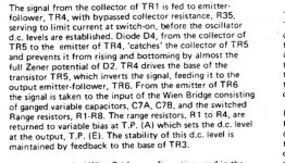
Indeed, there seems to be some sticking mechanism in play, though it may not be debilitating given that eventually a clean sine wave appears.
D4 should prevent TR5 from being driven into saturation and should begin to clamp base drive to TR5 when the emitter-collector voltage is driven within roughly 3V of saturating--- hard to be precise. You may be able to provoke this mechanism for steady-state examination by adjusting R34 for increased amplitude. Maybe you can capture some scope pics if there's any remaining mystery.
Increased sine amplitude might also be useful in exploring the suspicious waveform in the next-to-last pic.
More musing.
Schematic resolution is marginal, but I take C28 near TR5 base to be 470uF--- relatively huge. I'm not surprised bias stabilization to equilibrium is slow. Steady state behavior may be markedly different from power-on.
Schematic resolution is marginal, but I take C28 near TR5 base to be 470uF--- relatively huge. I'm not surprised bias stabilization to equilibrium is slow. Steady state behavior may be markedly different from power-on.
I hesitate to even suggest this thought, but if you become severely frustrated with the existing circuit and are adventurous, I think the oscillator active circuitry could be replaced with a TI OPA1656 opamp. Similarly, I think the power amplifier could be replaced with TI TLE2301.
Power-on behavior of the oscillator stage will still be slow because of the long bias time constants, but I believe the weird narrow spikes and spurious oscillation would likely be cured. I’m also very skeptical of the original power stage design. Both its circuit design and mechanical implementation (plus the repair history) suggest it was a work in progress.
I believe these modifications could be “graped in.” I have some thoughts about installing the TLE2301 on a small piece of double-sided copper clad without requiring etching.
If these notions don’t spook you, I can elaborate if you wish.
http://www.ti.com/lit/ds/symlink/tl...l-digikeymode-df-pf-null-wwe&ts=1589811907388
Hi BSST,
Thank you for your thoughts and ideas, I appreciate the time helping clueless folks like me takes! 😀
I have put the project on the back burner whilst I wait for a kit of parts to arrive, when I have them I shall have another crack at fixing this thing, taking the time in between to swot up on how amplifiers are designed and work as poking around blindly, knowing only enough to use a DMM, isn't going to cut it. 🙂
I like you idea of junking the guts and keeping the box with modern stuff in it, the build quality is all in the mechanical parts in this and the output transformer alone would be very expensive to buy new.
The specs of the chip you posted are certainly good enough for what I want, particularly the ability to drive low Z loads for speaker T/S testing.
Edit: On further reading I must confess however that much of that datasheet is beyond me, not sure what a "3 state facility" is for example... 😀
Last edited:
The “3-state” feature puts the TLE2301into a low power mode in which the output stage presents high impedance. I imagine the description come from digital IC buffers which often feature 3-states: high, low, and high-Z.
The suggestions below represent ideas I’d pursue if this were my own project but they’re certainly not gospel. You should apply your own ingenuity and skills.
The oscillator PDF depicts my thoughts re modification to incorporate an OPA1656. I’ve used “White Out” on the schematic to denote the parts I’d remove to disable existing circuitry; remaining components I’d leave in place as a “just in case” exit path. I’ve used one opamp section to drive the active shield since it’s conveniently present. The opamp IC would be installed on a SOIC-to-DIP adapter board and short lengths of bus wire would both establish connection to the oscillator circuit board and support the adapter mechanically. I’ve drawn the schematic to be suggestive of possible connection points to the PCB but adopt what seems most direct and robust. I recommend incorporating a 100nF ceramic on the adapter board to ensure good supply bypassing.
The amplifier PDF uses similar depiction of my tentative suggestions. I envision a small piece of two-sided PCB that would attach flush against the heat sink, anchored by the two screws that currently secure TR104 and TR106. The IC would reside in the middle between the screws. Small holes would pass pins 4,5,10,12,13,15 through to the bottom side. Remaining pins would be bent to stay topside with the IC body and clear of the top ground plane. (Careful to avoid fracturing leads where they enter the IC body.) Bend the through pins tight against the copper foil and solder both bottom and top to establish good electrical and thermal connection to both layers. Bits of bus wire can air-wire connections between 2,7 and 3,6 and compensation capacitors also air-wired. The unsupported IC pins need to be somehow protected from stress coupled from connecting wires to the “mother” board. I often thread connecting hook-up-wire connections through snug small clearance holes to limit transferred wiring stress. There’s lots of opportunity for ingenuity in this project. 😉
Maybe this is enough for now…
Steve
Attachments
Last edited:
This is amazing, I can’t thank you enough. I will need to research and read this all carefully but I am more than happy to implement your improvements, especially as you have gone to all this effort of my behalf! 🙂
Thanks again, I shall reply in substance once I’ve had a chance to go through it.
Thanks again, I shall reply in substance once I’ve had a chance to go through it.
Apologies for the delay in updates, I decided I needed to build myself a 0-60V 0-5A current limited power supply for... you know, stuff. 😀
With this power supply the oscillator starts up as per the book, I.e. builds up and dies off before building up and settling down again.
It still however shows hard clipping and the weird dip on the top plateau but it all settles much faster now.
I’m going to pull that diode is meant to prevent clipping and test it next.
I am struggling to find a TLE2301, there are NEE and NeE4 versions?
Edit: D4 tests fine, I will now obtain an OPA1656.
Last edited:
Mouser lists them. $6. Not sure what the difference it but I would go with the NEE since the datasheet only shows that. Probably something about either temp range or the like.
Thanks Demian, I prefer RS pares because Mouser UK is a shell and everything is posted Fedex from the US, at the moment it's a bit slow but I don't mind putting in an order.
The bits should be with me in a week or two.
The bits should be with me in a week or two.
Hi,
I'm late in responding, perhaps too late to be helpful. You may be able to order directly from TI. Pricing looks friendly to prototyping and the ordering website appears to have a UK address option but I did not explore enough to discover shipping charges--- they make this path unattractive. Bits of the TI order page are copied below.
Good luck!
TLE2301INE
ACTIVE
Excalibur 3-State-Output Wide-Bandwidth Power Operational Amplifier
Type : IC
Customer reference #
25 | TUBE
3,684
Box or tube 2
$4.19
$8.38
Coupon code
Apply
Subtotal$8.38
Order total (USD)$8.38
*Taxes are not included in the total
Continue shopping
Hi BSST, thanks for your efforts.
I’ve managed to obtain an original from a source over here, I have to wait a bit longer for the op amp.
I’m excited for this project! 😀
I’ve managed to obtain an original from a source over here, I have to wait a bit longer for the op amp.
I’m excited for this project! 😀
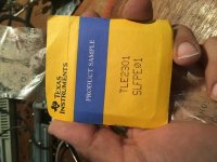
Tada!
By luck from eBay, it does say TLE23011NE on the actual chip.
I have gotten to thinking... 😀
This signal generator has an input for an external power supply, I am assuming because the transformer is unshielded in the case and might increase the distortion by a very small amount or something.
Would there any mileage in making a metal cage for the transformer and retrofitting some sort of more modern, quieter power supply on there?
Say the retrofit lm317 denoizinator on the power supply forum?
Attachments
- Home
- Design & Build
- Equipment & Tools
- Gould J3B signal generator repair help