SEE: Severe hum
I have fired up my SSE and there are a severe hum in the speakers, I still hear it when I leave the room with the door open.
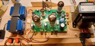
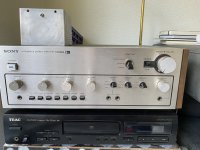
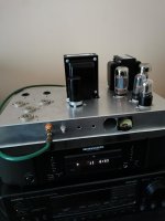
This is my first build and the setup are:
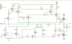
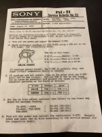
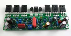
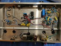
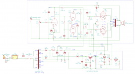
The amp are now configurated in triode without feedback (see pict)
The board are grounded via the PCB together with the zero point of T1, the center of 375-0-375.
Incoming signal are grounded via the PCB at the IN-connectors (pin 2 & 4)
Speakers are grounded via the PCB at connector T2&T3 sec
I have not grounded the power and OPT shields, it is on my ASAP to-do list.
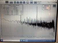
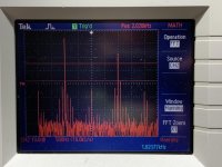
Measurments:
Things I consider to try out, in specific order
Will negative feedback help?
Shifting the sec of OPT?
I’m considering a choke. However are this related to cost (I have already exceeded my budget) and lead time, if I order today will I not receive it until next week, the weekend will be spoiled. Therefore is this not my primary solution, more like a backup.
Anything else, what have I missed?


This is my first build and the setup are:
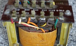
- Power: Hammond 374BX
- JJ 5AR4
- JJ 12AT7
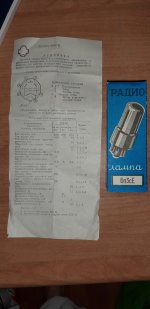
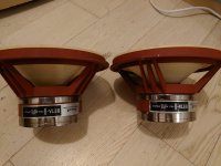
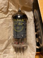
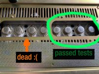
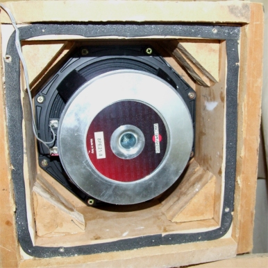
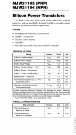
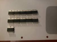
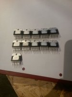
- Russian 6L6GC equivalent (see pict)
- OPT: Edcor GXSE15-8-5
- No choke, R1 = 150 Ohm
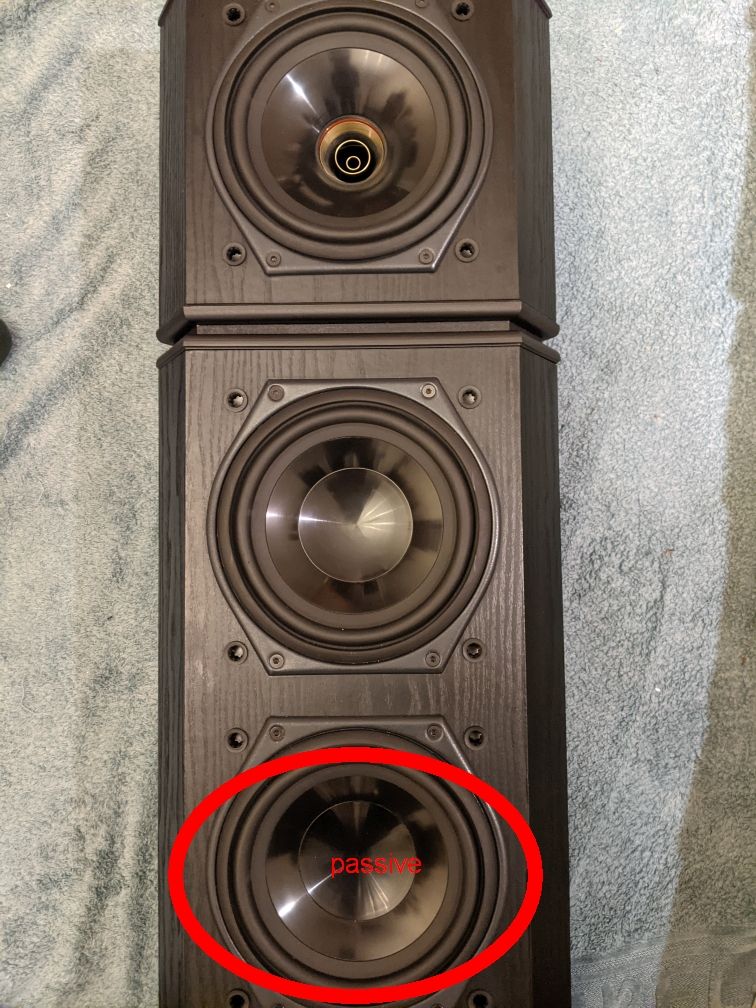
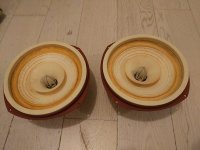
- Speakers: No name 8” + 1” tweeters from the 1995-isch.
The amp are now configurated in triode without feedback (see pict)
The board are grounded via the PCB together with the zero point of T1, the center of 375-0-375.
Incoming signal are grounded via the PCB at the IN-connectors (pin 2 & 4)
Speakers are grounded via the PCB at connector T2&T3 sec
I have not grounded the power and OPT shields, it is on my ASAP to-do list.
Measurments:
- B+ = 454 V
- R17/R27 = 680 Ohm, wired to the outside of the PCB for easy exchange during the test period
- U_R17/R27 = 35 V
- I = 35/680 = 52 mA
- P = (454-35)*0,052 = 21,5 W
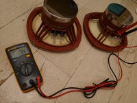
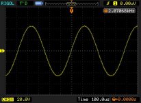
- VAC in idle on the OPT-sec are 24 mV on left channel and 54 mV on right channel, measured with my DVM.
Things I consider to try out, in specific order
- Ground the casing of transformers
- Twist power wires (5, 6,3 and 375 V)
- Add a capacitor at T1 red/yel-GND
Will negative feedback help?
Shifting the sec of OPT?
I’m considering a choke. However are this related to cost (I have already exceeded my budget) and lead time, if I order today will I not receive it until next week, the weekend will be spoiled. Therefore is this not my primary solution, more like a backup.
Anything else, what have I missed?


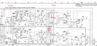


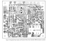


 I'm hoping someone may be able to shine a light over my recent trouble with a Rotel RB-970BX.
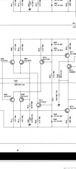


