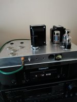
After a long while recovering from a fractured humerus at last I dusted up the soldering gun, and was able to put something together that surprisingly for me works quite well.
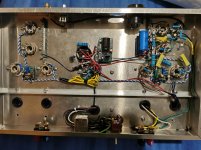
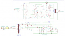
Attached the schematic and build. The point to point layout is a mess, I have never been a tidy builder, and is "great" to see things have not improved a lot in that area 😱
I get around 13.5V RMS on 8ohm before the distortion appears on the FFT, visually the signal looks and sounds quite good at up to 15V RMS. After that the first stage start drawing current (me guessing) from the LTP. The UL curves for a 5881 with Zp-p 6600 ohm and B+ 400V show a peak power around 29W so it seems to match quite well. 100 Hz hum is very quiet on my speakers (90db), need to go close to the speaker with volume pot to the maximum to hear it.
Things I'm thinking about before I build the second channel:
Adding the screen limiting resistors. Do we still need them for UL?
Adding a soft start to HV, it makes a relatively loud crack on the speaker when I turn it on (sign of something very wrong?)
CCS on the LTP. Does it improve things a lot?
Add a bigger capacitor to the power supply.
Any suggestions/criticism is very welcome.
I'd also like to thank the people in the forum for their very useful advice, especially (original thread: "Newbie looking for advice on stereo amp layout"):
@Eli Duttman for suggesting the Eico 89 as a fool proof starting point. Spot on!
@HighVoltageHit for layout recommendations and encouragement
@Tim Bavus for suggesting chassis reinforcement.
Regards,
Jose
Attachments
A fractured humerus is definitely not humorous. 😉
Have you measured frequency response of your amp? You might be getting some premature HF roll off with a 500k input level pot (or is that a volume pot?), when the pot is turned to the mid-rotation position.
When applying global loop feedback, the cutoff frequency created from R6/C3 may "get in the way" and lead to some marginal or full-on LF instability. But whether it's a problem or not depends largely on the output transformers. Have you checked your amp for LF stability?
Just curious how much global feedback is being applied?
A good CCS will force balance out of the differential pair, so it's mostly a good thing, but there are always inherently some imbalances down stream in the output stage and output transformers themselves. What matters most is perfectly balanced signals at both ends of the output transformer so that the phase correct and phase inverted signals get perfectly recombined inside the output transformer--that will produce the lowest distortion. My view though is if you have no better means of tuning the amp, a CCS is not a bad option.
If it "cracks" right at a cold start, that does point to something amiss in my mind. The tubes aren't conducting that quickly so it can't be coming from the audio circuit. May be due to some magnetic coupling or interaction somewhere with the output transformer.
I can confirm nothing humorous about that, I definitely was not laughing 🙂A fractured humerus is definitely not humorous. 😉
Have you measured frequency response of your amp? You might be getting some premature HF roll off with a 500k input level pot (or is that a volume pot?), when the pot is turned to the mid-rotation position.
When applying global loop feedback, the cutoff frequency created from R6/C3 may "get in the way" and lead to some marginal or full-on LF instability. But whether it's a problem or not depends largely on the output transformers. Have you checked your amp for LF stability?
Just curious how much global feedback is being applied?
A good CCS will force balance out of the differential pair, so it's mostly a good thing, but there are always inherently some imbalances down stream in the output stage and output transformers themselves. What matters most is perfectly balanced signals at both ends of the output transformer so that the phase correct and phase inverted signals get perfectly recombined inside the output transformer--that will produce the lowest distortion. My view though is if you have no better means of tuning the amp, a CCS is not a bad option.
If it "cracks" right at a cold start, that does point to something amiss in my mind. The tubes aren't conducting that quickly so it can't be coming from the audio circuit. May be due to some magnetic coupling or interaction somewhere with the output transformer.
The first pot is a volume one. I'd probably prefer 100K, but used what I had. I'll get some lower values. I did briefly run the amp at 15 kHz, did not notice any significan difference in the output signal, but I will do some more precise measurements, including open loop gain, gNFB level etc.
How would I check for LF stability? I did not notice anything weird with the oscilloscope, but maybe I was not looking in the right place.
I used 0.47u for C3 because I thought 0.1 would be a bit low, and had none clise to 0.25, which is what the HF-89 uses. Looking at other designs it seems that 0.47 is a bit too high indeed, I'll fix that.
Thank you for your feedback, appreciated!
You can test LF stability easily by setting up a dummy resistive load on the speaker connections, setup your scope to measure the signal at the dummy load. Then apply a signal to the amp's input and then remove that signal suddenly. Watch how quickly the scope trace settles to zero. If it takes a few bounces to settle it could be marginally LF stable. A well designed/executed amp should see that scope trace settle nearly instantaneously.
Try the same test with no speaker load but hit the input with a small amplitude signal so as not drive the output more than what would be about 1 watt if it were connected to a rated load on that given output tap. In the worst of cases I've seen, the amp breaks out into LF oscillation under those conditions. By LF oscillation I mean oscillating at several cycles per second.
Sometimes you can see LF oscillation, if it's egregious, by sending a HF signal through the amp (like a 10 KHz sine or square wave) when a dummy load is connected to the speaker terminals. You'll see on the scope display the entire wave jumping up and down slightly at several cycles per second.
Also 1M/0.47uF may not be too large. You may in fact need to make one or both of those components larger to address it. Then again you may have no problems at all in this area. Best to know by testing for it directly.
Edit: I just re-examined your schematic and see you are using a Hammond 1650-HA. Sorry I didn't see this earlier. My experience with Hammond output transformers is you will likely NOT have issues with LF stability given your circuit schematic if you are applying a moderate amount of feedback, say in the 12 to 14 dB range or lower. Still worth a quick test though...
Last edited:
Here are some measurements:
gNF, following Aikenamps' "designing-for-global-negative-feedback"
Ri = R2 = 100 ohm, Rf = R14 = 5.1K
Open loop:
V0 = 10.3, Vi = 57mV
Measured Aol = 180 (ground Ri)
Closed loop
Vo = 6.37v, Vi = 150mV
H = Ri / (Ri + Rf) = 100/(100 + 5.1K) = 0.0192
Calculated Acl = Aol / (1 + Aol* H) = 40
Measured Acl: 42.4: Close enough.
gNFB = -20*log(Aol/Acl) = -20*log(180/42) = -12.6 dB
>>Have you measured frequency response of your amp? You might be
>>getting some premature HF roll off with a 500k input level pot (or is
>>that a volume pot?), when the pot is turned to the mid-rotation
>>position.
Rough bandwidth measurements (dB calculated as 20*Log(V_F/10.1V):
Freq (Hz) RMS Output (v) (Vpot 100%)
1K 10.1 0 dB
10K 9.92 -0.16 dB
20K 9.76 -0.30 dB
50K 9.45 -0.58 dB
100K 7.3 -2.82 dB
Freq (Hz) RMS Output (v) (Vpot ~50%)
1K 10.1 0 dB
10K 9.54 -0.49 dB
20K 8.7 -1.3 dB
50K 5.67 -5.01 dB
100K 2.48 -12.2 dB
Bingo! it is affecting the bandwidth especially after 15 KHz. I have ordered some 100K and 50K pots to replace RV1.
I did the test you recommended to check for LF instability, but could not find anything abnormal. Turning on/off the input signal by results in the expected on/off of the output voltage.
Many thanks again, very useful feedback!