Some ages ago I built the Elektor current dumping amplifier. It was a good amplifier, I liked it!
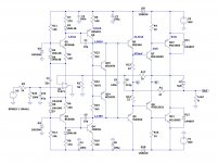
Last month I decided to revisit that circuit and after some research and several simulations I got to this improved circuit.
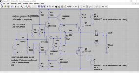
It has a class A stage followed by a class B and class C dumpers. And of course the famous Quad 405 bridge RLC network.
Now I have to order the PCBs and build the thing.
Mark Jordan
Last month I decided to revisit that circuit and after some research and several simulations I got to this improved circuit.
It has a class A stage followed by a class B and class C dumpers. And of course the famous Quad 405 bridge RLC network.
Now I have to order the PCBs and build the thing.
Mark Jordan
Nice to see some interest for this great design!
BTW You could benefit from a more linear opamp. Years ago I experimented with an OPA627 I think it was in one channel of my 405-2 and the distortion dropped markedly.
Jan
BTW You could benefit from a more linear opamp. Years ago I experimented with an OPA627 I think it was in one channel of my 405-2 and the distortion dropped markedly.
Jan
How is the bias stabilized?
It's a Sziklai endstage, stable on its own by the NPN-PNP compound.
Keep Q5-6 away from Q7-8-12-11.
(See: Hiraga designs)
How is the bias stabilized?
Mark, there is no bias in a current dumper amplifier, that's the whole idea of current dumping.
The class A low power drives the output at all times, and when the dumpers come in, the bridge feedback lowers the loop gain to avoid a kink in the transfer due to the additional gain provided by the dumpers.
Though, in later versions of the 405, Peter Walker used a single diode to keep the dumpers from shutting off completely near zero output, and that did improve performance.
Jan
BTW You could benefit from a more linear opamp. Years ago I experimented with an OPA627 I think it was in one channel of my 405-2 and the distortion dropped markedly.
Wouldn't opamp quiescent current have a marked difference on this circuit's bias levels though?
I might use a constant current source/sink to supply extra current. This may necessitate getting Q3/Q4 bases further away from supplies, losing a bit of voltage swing, but increasing R9/10 may not be a bad thing anyway.
If this approach works out, you could use an opamp with a more linear current draw, e.g. LF356 (which appears to run plenty of output stage bias current). Then the only issue remaining would be its common-mode nonlinearity - but since the opamp effectively already is cascoded anyway, one might modify this circuit to use common-mode bootstrapping. (I know, the OPA627 would be good, too, but I like doing things on the cheap...)
Last edited:
Though, in later versions of the 405, Peter Walker used a single diode to keep the dumpers from shutting off completely near zero output, and that did improve performance.
That's exactly why Q7/Q8 are biased in class B.
What do diodes D9 and D10 do besides decreasing maximum output swing?
And yes, I'm also somewhat sceptical about sensing the opamp's supply current and amplifying it's swings. There might be much better ways to translate signal swing from the opamp's +/- 15 V to the rails' level. For instance, look at how RCA has it done in the Power Transistor Manual or how ELEKTOR themselves did it in their 300 W PA amplifier.
Best regards!
Last edited:
Wouldn't opamp quiescent current have a marked difference on this circuit's bias levels though?
Yes it does here. But this concept was not used in the original QUAD, so there I could freely experiment.
Jan
What do diodes D9 and D10 do besides decreasing maximum output swing?
They prevent discharging C7, C8 when the supply droops with load bursts. Shottky's are a good choice here. But I would make those caps bigger.
Jan
That's exactly why Q7/Q8 are biased in class B.
Yes I noticed. About 500mV bias?
Jan
Actually, they may end up doing exactly the opposite, by keeping pre-driver supplies from being drained whenever the outputs are drawing some major current pulses. How much of an effect that has, not sure (it would depend on how saggy your rails are), but I imagine it doesn't take that much to outweigh the static drop of a Schottky. This may also be improving effective PSR.What do diodes D9 and D10 do besides decreasing maximum output swing?
I had been wondering about these, too, including why you no longer see them in more modern designs. I guess people have become more concerned with good power supply bypassing, keeping inductance low and all of that.
Ok, thanks, I see 😉. Anyway, continuous RMS output power (Sinusleistung in German) will be decreased, won't it?
Best regards!
Best regards!
I am perplexed. What is the output of the op-amp doing? Feeding Ground?
The power supply leads feeding the op-amp - they are actually the signal path?
Where does the "dumping" occur?
The power supply leads feeding the op-amp - they are actually the signal path?
Where does the "dumping" occur?
But Q7 and Q8 are close to conduction, so I can see the circuit drifting to pure class B when hot.Mark, there is no bias in a current dumper amplifier, that's the whole idea of current dumping.
The class A low power drives the output at all times, and when the dumpers come in, the bridge feedback lowers the loop gain to avoid a kink in the transfer due to the additional gain provided by the dumpers.
Though, in later versions of the 405, Peter Walker used a single diode to keep the dumpers from shutting off completely near zero output, and that did improve performance.
Jan
I am perplexed. What is the output of the op-amp doing? Feeding Ground?
The power supply leads feeding the op-amp - they are actually the signal path?
Where does the "dumping" occur?
The supply rail current of the opamp is indeed the class-B signal path. [ whoops, I was wrong here, there's 33nF: "There is thus a lack of decoupling for the opamp (not all opamps handle that well)" ].
The dumping is the output transistors not conducting at low signal levels, Q5/6 feed the output in class A via the 47 ohm resistor and at large signal swings the main devices switch on and contrubute (they are class C, basically). The output gain is thus lumpy across the voltage swing and crossover distortion is higher than standard class B (for large swings).
Last edited:
The output gain is thus lumpy across the voltage swing and crossover distortion is higher than standard class B (for large swings).
That's what you would expect but it is not the case thanks to the bridge feedback arrangement. That ensures that the 'lumpiness' in the gain through the signal cycle is cancelled. It's quite nifty!
The bridge has an inductor and a capacitor in opposite arms which (another stroke of genius from Peter Walker!) ensures dominant pole compensation and inherent stability.
There is a very detailed discussion by Vanderkooy and Lipshitz in an AES paper that give a very nice analysis of the concept. I'll see if I can find it.
Edit - found it, attached.
Jan
Attachments
Last edited:
- Home
- Amplifiers
- Solid State
- Current Dumping revisited