Hello,
I've got this posted on the Dynaco tube forum but am also posting here to cast a wider net. This is about my M-125 monoblock build (tubes4hifi).
I am looking for some debugging advice to help me narrow down something that has been bothering me. My right monoblock is not as loud as my left one. I've been using the gain on my sp14 to compensate (about 4 clicks), but I want to figure out why it is softer. My conclusions so far:
- it's not just room acoustics - at low volume listening a foot from the speakers the right output is obviously softer
- it is not the speaker or speaker cable - I swapped them and it follows the monoblock
- it's not the input - I switched the rca cables
- it is not the output tubes - swapped all 4 KT-88s between monoblocks
- it is not the driver tubes - swapped them
- voltages at all 8 pins on the 4 output tubes are all within published range.
I don't hear any audio artifacts. They both sound great to my ears, it is only a volume difference. But I want to isolate what is different and am asking for advice on how to do that. Are there measurements I should be taking at the speaker binding posts? Could a bad soldering job there cause this? Could it be a wrong/bad component on the board?
Thank you
Check the feedback connection
If the opt secondary isn't feeding back due to an open feedback loop, then you'll be looking for the problem in the higher gain amplifier.
The louder one
Verify the opt secondary has both a ground connection and a feedback connection on both amplifiers.
If the opt secondary isn't feeding back due to an open feedback loop, then you'll be looking for the problem in the higher gain amplifier.
The louder one
Verify the opt secondary has both a ground connection and a feedback connection on both amplifiers.
Is this ultra-linear amp? Have you check the windings?
One way to debug is to injet tone or music (via high voltage cap) into various input stage and compare the sound level.
One way to debug is to injet tone or music (via high voltage cap) into various input stage and compare the sound level.
Thank you for the response. Sorry, but I don't know enough to act on your advice. Could you give me a little more info on this so I can figure out what I need to check?
Thanks for the response. It has a switch to play in ultralinear or triode. I verified the switch is not wired backwards (quieter in triode mode). I din't know how to check the windings. I will look for more details on injecting a tone into input stages.
You can burn a CD with various test tone freq if you don't have a tone generator. The CD gives 3V output you can reduce it with resistor/attenuator. Use a high voltage capacitor to isolate high DC voltage. Use DMM in AC range to measure the output on speaker posts.
P/S I recommend you get some of this:
https://shopee.com.my/SHNGki-Profes...Flexible-Testing-Probe-i.163592123.4617929590
P/S I recommend you get some of this:
https://shopee.com.my/SHNGki-Profes...Flexible-Testing-Probe-i.163592123.4617929590
Last edited:
Midnight Mayhem - I double checked the ground and NFB connections and they are both wired correctly and look to be soldered well.
I did notice the wire grounding the black speaker jack on the right (softer) monoblock is much thinner than the wire grounding it on the right one. Looks like 20 gauge versus 14. I accidentally wasted wire from the kit and had no thicker wire left. I wouldn't think this would matter but wanted to check.
IEales in here has experienced and on his website about this amp. I personally emailed him couple times.
Teaching VTA M-125 to sing
ieLogical VTA M-125
Teaching VTA M-125 to sing
ieLogical VTA M-125
I did notice the wire grounding the black speaker jack on the right (softer) monoblock is much thinner than the wire grounding it on the right one. Looks like 20 gauge versus 14. I accidentally wasted wire from the kit and had no thicker wire left. I wouldn't think this would matter but wanted to check.
It shouldn't as long as it connects to signal ground with the first cathode resistor.
The secondary needs to put current through the load(speaker) as well as the negative feedback network which includes the cathode resistor, on both amplifiers.
Gauge of wire is less important than verifying that the circuit is intact and working.
Make sure that all the output transformer secondary wires go to the correct terminals,
and also that the feedback connection is from the correct terminal.
Sometimes an internal resistor can be different than was intended.
Check at least the feedback resistors for value.
and also that the feedback connection is from the correct terminal.
Sometimes an internal resistor can be different than was intended.
Check at least the feedback resistors for value.
Last edited:
Post some pictures please,we may notice something you don't. The pics don't need to be 50 million mega pics, just good quality and from a few angles so that we can see all the components and wiring.
Have you got a multimeter to check voltages? The # 1 rulein electronic de-bugging is " Tholt shalt check voltages" . The idea is to compare the readings from a good known working channel, to one that you think is faulty.
Andy.
Have you got a multimeter to check voltages? The # 1 rulein electronic de-bugging is " Tholt shalt check voltages" . The idea is to compare the readings from a good known working channel, to one that you think is faulty.
Andy.
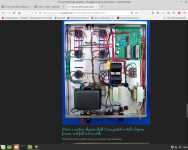
Here are pictures of the right (quieter) monoblock. Will post pictures of the left as well. You will see from the pictures I am new to this and my wiring management is not very good. I am definitely open to all criticism about the quality of my work if you think it may be contributing to the issue. I do own a multimedia but am not good at reading schematics so I need to know what voltages I am looking for. The expected voltages at the pins of the output tubes are specified in the manual and I have measured the 8 pins for the 4 output tubes on both amps. All readings are within the range specified. For comparing voltages between channels I should have a tone generator shouldn't I? At this point I am willing to buy one if it is needed to resolve this - if you have any recommendations please let me know.
Right (quieter monoblock):
https://www.amazon.com/photos/shared/Yj_ZzY6gSQisj3VARqHn2g.CiwRCnhuyGlwM5axgrDizv
Note - you will see the resister on V2 looks different. It is a 1000 ohm 1 watt resister like it is supposed to be, and the problem predates my needing to replace this resister. I have Vishay resisters coming and will replace it will a physically larger resister for better heat dissipation.
Last edited:
Left (louder monoblock): https://www.amazon.com/photos/shared/YMwofMnHRiqbbkeP-N30Ng.3_tyshaeQ4gW9THdsT610Y
The wiring is less than optimum, it makes fault finding more difficult. It should look more the pic attached. I can see a few other less than perfect oddities but nothing that jumps out as a possible cause for your issue; others might do.
As mentioned this needs some voltages taken and even better a look at with a scope. However, there is one thing you can do, that's swop valves between the two. Start with V1,then work your way through. Don't know what V1 is, tried to find a schematic for your build in the little time I had, nothing.
One thing though, make sure you leave the OP valves to cool down a bit and caps to discharge between each swopping of valves/power up, else you may blow something.
Andy.
Attachments
Acknowledged on the wiring. I have eliminated input from the preamp, speakers/cables and output tubes as a cause by swapping them between the two amps.
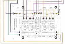
Do you have missing connection? In your snapshot, the autobias module you have V1,V2 ground pad not connected to anything?
Attachments
Last edited:
I do not believe I have a missing connection. The diagram shows a dotted line connection to V1 and V2 GRD. The instructions with the board do not include any connections to those. V1, V2, V3 and V4 bias readings on the tube sockets are all consistent (around .5 V)
How many volt on top 100k grid resistors (KT88)? I suppose the grid bias voltage is around -50V.
P/S between cathode and grid, how many volts?
P/S between cathode and grid, how many volts?
Last edited:
From v1-v4:
Pin 1 - .462 .462 .458 .459 (autobias recommended .45 for KT88)
Across pins 2&7 - 6.6 6.6 6.6 6.6
Pin 3 - 512 511 512 511
Pin 4 - 513 513 514 513
Pin 5 - -59.8 -60.1 -59.9 -60.4
Pin 6 - -59.8 -60.2 -59.9 -60.4
Pin 8 - .462 .462 .458 .459
Voltages for the left amp are basically the same (very minor voltage differences)
- Home
- Amplifiers
- Tubes / Valves
- M-125 Monoblock Debugging Advice