Modifying the output stage of the miniDSP 4x10HD

The output opamp of the miniDSP4x10HD is an JRC2068 with a DMP8 outline. As i have the idea to replace this opamp i just compared the outlines and footprints of DMP8 and SO8 packages. It seems that the footprints differ not too much - so a SO8 opamp should fit into the footprint of the DMP8 package. Has anybody done this change yet?

Is the C in series to each output really needed? The opamps have dual supply rails and the signal coming from the DACs output is symmetrical, so i assume there is no DC offset at the output (not verified yet). If i am right i think it could be replaced by a simple piece of wire... any opinions anyone?

Introducing the Hermes-Amanero

Hello Folks,

You can get the Hermes-Amanero (along with the Cronus/Rhea) here:

Cronus Reclocking

This module allows you to use the Amanero with the Cronus in a fully isolated manner with the Amanero in slave mode - and the Cronus providing the audio master clock.

This give you an ideal isolated USB audio solution that supports PCM/DSD(via DoP implemented in the Amanero)

All frequencies from 32Khz to 384Khz are supported and transitions between 44.1 and 48Khz sample rate families are seamless.

I am currently (and strongly recommend) using the following configuration.

Cronus:
45/49Mhz clock with Hermes clock output set to 1:2 - this means the Amanereo is sourced with 22/24Mhz - while the clock for reclocking (and optionally the DAC) is 45/49Mhz.

Amanero:
CPLD Firmware = "Slave_For_1080"
CPU Firmware = "firmware_1096c" or "firmware_1095b" - but do not use "firmware_1095c" as it is broken.

Hardware setup is very simple - just connect the appropriate headers and stack the Amanero with the Hermes (either on top or bottom depends on your needs) Then stack the Hermes (once again either top or bottom) on the Cronus. This makes the interface very clean and short - and at the critical point (the Cronus outputs) everything is time aligned with the Cronus master clock.

I have tested this combination in Windows using Foobar and on my MacBook Pro using Vox and other players.

PCM and DSD both work fantastically and play lists that move between sample rates and DSD/PCM types work as expected with no pops (using a B3SE) or any other nastiness. The highest sample rates work perfectly (352/384khz) with the firmware indicated above.

I am very pleased with the result - and since everything is perfectly time aligned with the Cronus clock from input to output the audio signal is clean and pure. No data errors - no data loss - no isolator induced phase noise. With Hermes/Cronus there is no need to for anything else between you and music.

This is not really simply reclocking - it is in fact simply a perfectly time aligned USB source.

This is the simplest way to use Cronus - and works very well even with usb hosts like the rpi-2.

Cheers!
Russ

Attachments

  • hermes-am.jpg
    hermes-am.jpg
    33.1 KB · Views: 4,495

ACA 1.8 chassis static electricity

Hello fellow enthusiasts,

My recently built ACA 1.8 amplifier works out great. It seems to operate silently without any hum whatsoever.

When I wanted to feel how hot the heat sinks get, touching the chassis (or heat sinks) resulted in a feeling alike tickling.

So, I switched off the amplifier and waited for cooling down. When I gently touch or stroke the chassis (off, being cold) it feels like the chassis is charged with static electricity.

When disconnecting the 24V power source from the kit the problem goes away. Note: my wall socket is not grounded to earth.

How should I proceed? Is this a problem at all, and how can I measure to pin point if it is and what to do exactly?

Thanks in advance!

Best regards,
Kees

Discussion on making R2R DAC chip by TSMC

Ti's ina1620 integrates a thin-film resistor. It is said that the accuracy of this resistor is very high. Is it more accurate than the resistance corrected by laser in the R2R chip? If the semiconductor process resistance is more accurate, does it mean that TSMC is theoretically capable of manufacturing R2R DAC chips with 32 bit accuracy? Is the cost lower than the previous manufacturing process?

2452.JPG

Valve/Tube HV regulator

I'm looking for a very good (objective & subjective SQ) HV tube valve base regulator, looking for information I see at AudioXpress the attached schematic but I need to know:

-Max. Vin & Vout
-Min. Vin & Vout
-Max. & min. current

I guess is a very good tech design, also I have on hand the valves & sockets, suggested ideas to improve will be welcome.


TIA
Felipe


1642625595345.png

A good TIA/inverting gain block idea?

I need a good output amplifier for a generator. Specs are pretty normal: 30Vpp output, 1MHz bandwidth, 50 ohm capability, but I also want sub-ppm linearity performance, which seriously complicates matters.
However, thanks to the topology, I only need an inverting configuration, which somewhat eases the problem: no need for a NI input, and no common-mode induced distortion.
This makes me think that I could get away with a relatively simple configuration, whereas an opamp-like topology would require two or three dozens of transistors.
I didn't find any satisfactory solution so far, neither of my own nor internet-inspired.
Does someone have a good (clever) starting base to propose?
The impedance level is relatively low, which should also simplify the problem.
This summarizes what I am looking for:
TIA.png

Musical Fidelity MA50 paralleled output question

The MA50 is basically same circuit as A1.

It parallels the two channel of outputs together to make it mono.

the way it parallels couldn’t be simpler, as you can see, it just uses a green wire to link two positive terminals together. Anyone can do the same to any stereo amp by just using a jump lead.

My question is wont the way they did to parallel cause a problem? If the two channels are imbalances in voltage, say due to ageing or something, wont it be causing current feeding from one channel to another?

Is any modifications possible to make it more reliable? Like using link in a diode in each of the channel output provides some protection?
7CAE7ACF-A294-4EEC-A7E7-F551E5CD26BA.jpeg

6820C3AF-BD76-4E6A-8329-9DFE1CFF7B14.jpeg

Low distortion amplifier (LDA) non-profit kits

Hi,

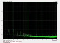
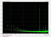
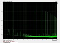
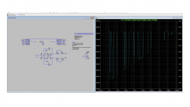
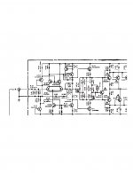
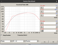
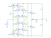
I have a low noise, low distortion distortion transistor audio power amplifier design. Built 2 mono and 3 stereo prototypes so far that work fine. This is a DiY design, but I believe it was more carefully tested under non-ideal conditions than the majority of DiY designs we encounter on the internet. The 1 kHz THD was measured 0.0006%...0.0013% on the prototypes depending on power level and load (loads down to 3.5 ohms, output power from 0.2 Watts up to 200 Watts /3.5 ohms). Below 0.2 watts, distortion harmonics are masked in the noise floor of my equipment even with averaging. Other kind of more challenging distortions like 19+20 kHz IMD and TIM(DIM) -- see images -- are low at all power levels and at all permitted loads. Capable of 200 Watts/ 4 ohms or 110 Watts /4 ohms output power depending on component set.

A nulltest (google "audio nulltest" if you don't know what it is) showed that the amplifier has no audible distortion at normal listening volumes, so it can be considered as totally transparent sonically. (Well, I understand some people like audible distortions if they color the sound pleasantly or interestingly. So this amp is for people who rather like reality.)

My open-ended offer is that I send you the kit you choose (one of the 4 different kits that are available) at a non-profit price. This means you'll get the specified PCB's and components at the price I bought them, and I won't charge my wage of labor either. I do this to make this design and the kits more popular among DiYers. I only ask in return: please give me feedback how I can improve the completeness and quality of the online information, especially the assembly instructions.

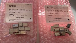
All kits contain the low distortion power amplifier board(s), power supply board(s) and protection board(s) and the components to populate the boards as covered in the online documentation. (User selectable components like chassis, main heatsink, main filter capacitors, power transformer(s) etc. are not part of the kits.)
http://euraudio.dx.am/en/amp/LDA/lda_np_kits_en.htm

The home page of the LDA amplifier is this, where you'll find links to all information that is available right now (kit descriptions, specifications, assembly instructions, some measurements and listening tests):

LDA home

The circuitry is more complicated than the majority of DiY projects, it is not for beginners. If you don't have proven experience in audio amplifier construction, please don't buy it! (If you make a mistake and some components are blown, I can't help in troubleshooting, I can only resend the whole component set for the faulty circuit at the non-profit price until this sale is offered.)
The LDA MIN_np kit is the simplest and cheapest (2x100W stereo) kit of the 4, it has only a minimalist protection circuitry. The LDA 53DM_np kit is the most expensive and most reliable (2x200W dual mono) kit; regarding protection, it survived 3 output short circuits during the testing without degradation of output signal quality due to the fast acting ultra low distortion solid state relay in it.

You must pay the shipping costs, which may be significant outside of Europe (shipping is from Hungary).
Right now I have in stock components for 4 mono amplifiers (or 2 dual mono or 2 stereo). If there will be interest in more non-profit kits than this, then I'll need about 2 weeks to buy the necessary components.
Most of the kits are available on the German and UK ebays and some of them on the Hungarian vatera.hu. The price there contains the fee I need to pay ebay or vatera for the transaction.
If you are in the UK, in Germany, in Hungary, or in an English speaking country where ebay is present, then you can ask me to list your chosen kit on ebay if it is not listed.
If you're in another, non-English speaking country, I think you should transfer the non-profit price of the kit + shipping cost to my PalPay account in advance, which you could rightfully consider unsafe. Still thinking about registering on Amazon...

If you have any question, please ask.

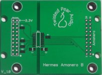
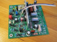
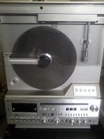
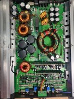
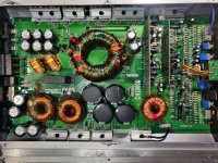
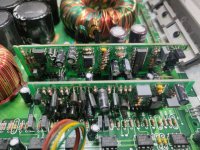
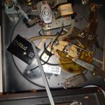
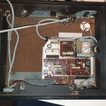
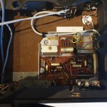
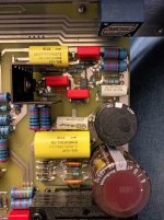
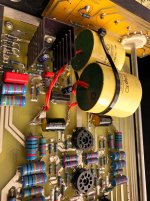
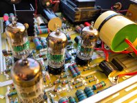
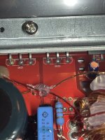
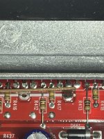
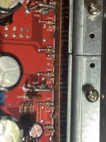
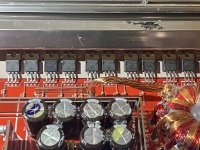
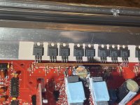
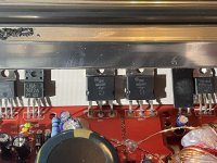
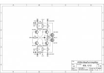
[The image shows only the amplifier board without the output transistors and the tempco transistor. Those transistors are also part of the kits as well as other PCB's with the components specified in the assembly instructions, which, in most cases, are all the electronic and mechanical components that populate the PCB's.]
http://euraudio.dx.am/en/amp/LDA/LDA_53DM_np_assy.htm
http://euraudio.dx.am/en/amp/LDA/LDA_43S_np_assy.htm
http://euraudio.dx.am/en/amp/LDA/LDA_53M_np_assy.htm
http://euraudio.dx.am/en/amp/LDA/LDA_MIN_np_assy.htm

Istvan

Attachments

  • 1kHz_THD.jpg
    1kHz_THD.jpg
    182.1 KB · Views: 841
  • 19+20kHz.jpg
    19+20kHz.jpg
    188.8 KB · Views: 794
  • DIM.jpg
    DIM.jpg
    202.8 KB · Views: 835
  • LDA172hc_assd.jpg
    LDA172hc_assd.jpg
    305.8 KB · Views: 876

Driver board Question

I noticed on this board that R10 has been changed not sure if it from the factory or someone tried repairing it themselfs .

right now it has a 5.1K resistor .
Does anyone know the correct value ?

Also does anyone know what the purpose of this resistor is ?

also should the pins have a jumper on them set to 9 volts ?

it came out of a 10 k amp

Attachments

  • DD26FA7E-1E50-4986-AC18-CA1CD38B34EE.jpeg
    DD26FA7E-1E50-4986-AC18-CA1CD38B34EE.jpeg
    576.6 KB · Views: 115

Distortion in 20 year old push pull transistor ahuja amplifier

I have a 20 year old ahuja push pull amplifier. The problem with that is distortion.I dont know how to eliminate the distortion. I am linking a model of my amplifier but it is not the exact circuit diagram of it but it resembles my amplifier.the same problem exist for another amplifier which is also 15 years old. but there is no other problem. i want to make it as a distortion free amp. i will try to give every details of that amplifier if you ask what you need like parts present in it Thank you for your help


http://www.diyaudio.com/forums/atta...01d1305291115-ahuja-amplifier-scan0002-1-.jpg

LTspice Tian Probe Fully Differential Amp

Hi Folks,

I am new to LTspice and trying to run a loop gain stability check on a fully differential amplifier. Thanks to this forum (especially Dave Zan), I managed to download an example amplifier with Dave Zan's balun.

When I implement the balun probe, and try to run the Tian method for Loop stability, results seem garbage.

Am I doing something silly? Why is the loop gain looks garbage? It is a simple circuit,

thanks!

Attachments

  • AD8137_test.asc
    AD8137_test.asc
    6.2 KB · Views: 161
  • Tian_loopstability_snapshot.001.png
    Tian_loopstability_snapshot.001.png
    48.8 KB · Views: 383

  • Locked
FS: Rek-O-Kut Rodine Jr with AT-1005 arm

I"m selling my trusty old Rek-O-Kut Rondine Jr with outboard motor. It has an AT-1005 tone arm in excellent condition and comes with a VM95E cart and also a Stanton 680 with conical stylus. This is a pinch roller type drive, but I use a little outboard motor which is much, much quieter. The original motor is still installed, but one of the idler wheels is missing (where did I put that damn thing?). New ones can be found.

The platter is nice and heavy and runs very smoothly on a ceramic bearing. The underside of the platter is coated with a 3M anti-vibration spray. The spray and the bearing significantly reduced rumble, and the use of the outboard motor of course made for a huge drop in noise. Silicon+Teflon oil for the spindle and bearing works well.
This is already a nice turntable, but with a better/stronger motor and maybe even a better plinth it will be excellent. The AT-1005 arm was a big upgrade from the original Grado tonearm. I'm the second owner. This turntable sat unused from 1974 to 2011 when I bought it and brought it back to life. Many hours of enjoyment and good music have been had in the past ten years. I'm sad to see her go, but it's time to say adieu.

Price is $125 which will be donated in your name to diyAudio.com You pay shipping from zip code 33904. The box is 20x20x9" and weighs 24 lbs. It will be a bit pricey to ship if you are on the west coast.

ROK-01.jpg
ROK-02.jpg
ROK-03.jpg

SystemD_2kW, any interest for an open design?

SystemD_MD is by far to complex for an open DIY design.
Also I have the feeling that the class D community is heading for higher power.

Since two weeks I am thinking about a DIY friendly design, that could deliver about 2kW into 4R in bridged mode. I am considering to develop this as an open design for DIY class D enthusiasts.

Rough outline of SystemD_2kW:
- Useable as a halfbridge with 1kW/2R
- Useable in bridged mode with 2kW/4R
- High performance and well balanced properties, but of course not as blameless as SystemD_MD
- Simplified implementation of the triangle shaping method known from SystemD_MD
- Instead of mostly discrete, heading for a reasonably simple design
- Selfoscillating, because that's the way to keep component count attractive for DIY
- Hysteresis oscillator, not UcD
- Restrict the really critical parts to MosFets, level shifter and layout

Why a hysteresis oscillator, while the entire classD world is on the UcD trip (or on the IRAUD trip with delta sigma...)?
Compared to UcD the hysteresis oscillator needs just two resistors more and offers the chance to adjust the frequency shift by a dynamic hysteresis control.
At this point I have to highlight, that I am not the only one who has thoughts into this direction. I will post my circuit for the dynamic hysteresis control soon and would love to see postings with different circuits for a dynamic hysteresis control of other enthusiasts, in case you are willing to share it with the DIY community.

What is the best Amp with DSP ??

Hey guys I'm looking @ the Wondom Jab5 amps. I would get 2 of them to run each of my 3 way speakers.

I was just reading around the forums and people were complaining about the sound quality of these amps. Has anyone had any issues with the SQ of them??

I have a zoudio amp, but it seems I only have 4 channels, and I can not output signal to another amp...

Is there another 4 or 6 channel amp out there that allows you to pass through the signal? or any other amps out there that will get the job done? (DSP)

Thanks guys !

Acoustic Energy AE1

Hi,
one of my AE1s has gone kaput.
The mid/bass voice coil is rubbing, well more accurate to say, almost locked solid.
It must have overheated and on cooling became distorted.

Does anyone know of a replacement driver that fits the cornered rebate and is a good substitute for the T/S parameters of the original?

The last time I replaced a driver, Acoustic Energy took £75 off me for an exchange unit and that was about 12years ago. I don't even want to ask their price for one now.

When not logged in, names of threads are hard to read (font too thin)

Before logging in, the display of newest posts uses a very thin font that's quite hard to read. I've seen this behavior (images below) on Brave, Chrome, and Firefox. After logging in, it gets much better. I think visitors to the site might be a little put off when the content is so difficult to read. People who haven't become members yet.

edit- oops! This seems to be the "default style theme" while I have chosen the "classic theme" when logged in. Sorry for my confusion.


_

Attachments

  • nli.png
    nli.png
    12.5 KB · Views: 112
  • yli.png
    yli.png
    16.7 KB · Views: 103

Rare Mitsubishi MC-8000 - Amp Channel Issues

Hello DIYAudio

I have inherited a rare Mitsubishi MC-8000 aka X-10 ...
this is a Vertical Linear Turntable with a builtin Amplifier/Tuner/Cassette !

Date of build is 1981

Problems with its amplifier -
Appreciate any help I can get to get this working and keep it out of the trash!

Was told it powers up ok when it was given to me -
- however on power up the Right channel is silent.

Left Channel worked sort of - Sound could be heard but then the volume decreased and static heard - this happens intermittently
and at the same time the volume decreases the units VU Meters lamps would dim.!

After dissasembly I found right channel output Fuse F821 3.15Amp Blown

The Amps IC is a Sanken Dual Channel SI-1135HD - I believe these have been used in other Amps (Rotel) Only a couple on Ebay I could find
(however are they fake?)


Thanks in advance for replies - what are peoples thoughts... how best to test/check the module? - approach to finding the exact problem given the symptoms?

If it turns out to be the Sanken SI-1135HD wonder is a comparable alternative IC Amp available ?
Suppose if not and its the Sanken then I could try and retro fit a Class D Amplifier Module...

Any thoughts on the above most appreciated

Attachments

  • mitsubishi-mc-8000-vertical-linear.jpg
    mitsubishi-mc-8000-vertical-linear.jpg
    26.4 KB · Views: 654
  • MC-8000-AMP-SEC 1.jpg
    MC-8000-AMP-SEC 1.jpg
    305.7 KB · Views: 487
  • MC-8000-AMP-SEC 2.jpg
    MC-8000-AMP-SEC 2.jpg
    284.1 KB · Views: 437
  • MC-8000-AMP-SEC 3.jpg
    MC-8000-AMP-SEC 3.jpg
    283.6 KB · Views: 610

Suggestions for 50W Mono Class D PCB which can drive 4-16 Ohm speakers

Hello,

I'm interested in a Mono Class D amplifier PCB or populated PCB which can drive 4-16 Ohms speakers to approx. 50W with reasonable THD. This is for an instrument amplifier, so THD up to 0.1% (max.) would be acceptable and a frequency range 60Hz-18kHz would be transparent enough for the application.

I see some very cheap PCBs on eBay/AliExpress and more expensive PCB from various other companies.

But this needs to be reliable, I want something that last and won't blow-up! Any suggestions?

Designing my own is an option and would be fun, but I'm much rather use something that is already well designed and tested; why re-invent the wheel.

What's an appropiate Powersupply for this 50w amp?

First of all, this is my first time trying something like this. I got my hands on a broken Logitech Z623(some of the electronics got fried) and I'm planning on using just the subwoofer as a speaker. I've been looking for a bit and found this amp that seems good to me. Now I'm not sure what to power it with. Perfect would be a mobile solution(battery), so I can bring this speaker places. But all I've been finding requires a cabled PSU(which can't be right lol).

Does anyone know how to properly power that amp? Sorry for the noob question

Compact amplifier recommendations

I am thinking about replacing our ancient CRT television to go for one of those new-fangled thin ones to hand on the wall. Noticing that the sound is pretty much crap on these I would have to buy a sound bar what would add to the cost. I can't see how something so skinny can be that good so I came up with an alternative idea.
I have a pair of very nice B&W bookshelf speakers (8ohm) that are never used now that I have finished building my Paul Carmody Tarkus floorstanders. All I need is a two channel amp to drive them and I could use this setup (plugged into the headphone socket) of the TV to get better sound. I'm not keen to spend a huge amount on an amplifier and have been looking at secondhand Sony amps online but they are not only silly expensive but I'm thinking something much more compact might make sense. A see lots of tiny amps from China but although they are cheap they usually don't come with a power supply and many are mono only so the price just goes up and up.

Any recommendations?

Boss CH3000D remaining on and thumping

Have a Boss CH3000D monoblock here that has an issue where the amp would thump the subwoofer in and out repeatedly when powered up and the amp powers up with remote but remains on when remote is removed and only turns off when RCAs are unplugged.
I found that the bass boost knob when turned would cause the subwoofer to pull in and out also. The knob was swapped out but the problem still exists. After changing the bass boost knob the amp would turn on and had clean output when tested in a vehicle but the thumping returned at high output level and then when the remote was turned off, the amp remained on until the RCA plugs were removed. There were a few strands of wire still soldered to the case of the input voltage selector switch as if there was a ground jumper that came off. I resoldered a wire to it and screwed it down to the regulators heatsink clamp but nothing changed.

Attachments

  • IMG_20220112_221638.jpg
    IMG_20220112_221638.jpg
    717.9 KB · Views: 169
  • IMG_20220112_221710.jpg
    IMG_20220112_221710.jpg
    754.9 KB · Views: 143
  • IMG_20220112_221734.jpg
    IMG_20220112_221734.jpg
    521.6 KB · Views: 166

Port size is uneven

I'm building a subwoofer that fits into a space at the rear of my minivan. Because of design constraints my port starts at 1.75" wide and 8.5" high for the first 26.5"
It then goes from 8.5" to 9.5" (x 1.75") for a 1" stretch
and the last 2.5" is 9.5" Total port length = 30"

I'm using a width of 1.75" and a weighted average height of 8.7"

I have no clue how It will tune, I know it won't be the same as if it's one constant size, but will it be close? I haven't found anything designed this way, normally that's because it's a bad idea. Should I find another Solution?

For Sale Neurochrome Modulus686

Unfortunately, I have to sell my beloved Neurochrome Modulus686. About 2 months ago my home theater receiver died an horrible death and took with it 3 speakers... I now have to replace the system since my family and I watch a lot of movies... A new Onkyo RX-TZ50 to replace the even more expensive one I had (Integra), and since the speakers that burned are from an older series from 10 years ago, I cannot find anymore, then I have to change most speakers as well... Sucks... badly..!
Since the Neurochrome is the only amplifier I own, that I know I can what I want for (as you all know, anything DIY is always hard to sell for even the cost of parts), then it is the one I have to sell. I guess I will build another one down the road, but for now, I have to please the whole family, not just the selfish me...

Here's pictures of my build on Tom's thread
- It is using Neurochrome's ISS Softstart, Guardian-686 speaker protection, Mod-686 modules and SMPS PSUs in a fully dual mono config. Both XLR and RCA on the back, switchable.
https://www.diyaudio.com/forums/ven...-power-amp-extremely-low-thd-post5684470.htmlhttps://www.diyaudio.com/forums/ven...-power-amp-extremely-low-thd-post5684773.htmlhttps://www.diyaudio.com/forums/ven...-power-amp-extremely-low-thd-post5684780.htmlhttps://www.diyaudio.com/forums/ven...-power-amp-extremely-low-thd-post5693718.html
This sale is still very fragile as I'm still debating this decision... It's one of those you're never sure about... Anyways, I'll accept request but allow me 2-3 days to think it over...

Price is firm 2300$USD + shipping (not responsible for any shipping taxes, customs, duties or any other fees)

Do

Counterpoint DA-11.5E CD Transport Not working

Hi all,

I have a CD Drive Counterpoint which is not working.
See picture 2 for overall view


Symptoms are:
-No life sign
-If I push power button I can hear the relay switch (clic)
-If I let the tray open, he's closing automatically which is mean that there is power.
-no light on
-nothing is displayed

starting of my troubleshooting:
-Power source is working
-The previous owner has already try to fix (or get fix) the CD drive. there is a bypass between the optical module PCB to the upper PCB which I definitely not understand.. (See picture 3)
-I didn't check if power is arriving to microchips (next step).


The aim of my post is firstly to share my troubleshooting and (I hope) the repair solution.
Then to ask all of you: Are anyone a good tip to found the counterpoint DA-11.5E SERVICE MANUAL ??

thank you very much in advance 🙂

Attachments

  • image2.jpeg
    image2.jpeg
    726.9 KB · Views: 247
  • image3.jpeg
    image3.jpeg
    397.2 KB · Views: 225

Is high voltage Mosfet capacitance multiplier bypass cap necessary?

Does a high voltage Mosfet capacitor multiplier supply for a valve power amp ( PP class A) need a bypass cap, say, to discourage oscillation? If so, is there any way of determining safe start-up conditions so as not to breach the Mosfet S.O.A., for instance, scaling the bypass cap with the time constant of the filter in the gate circuit to limit current into what is, to all intents and purposes, a short circuit at t=0? Merlin Blencowe has a neat trick in his Preamp book for soft current limiting using the gate to source protection Zener and a resistor, but I think I would prefer that this limiter was not constantly strained at switch on. I've seen quite large bypass caps on BJT cap multipliers which would surely destroy a Mosfet in a microsecond or less.

Many thanks for any ideas and/or experience.

Fully active and sealed, the ultimate Purifi driver implementations.

Hey guys,

Thought I’d make a thread for those interested in getting the very best from the SOTA Purifi driver lineup. And for those of us on the cutting edge, we all know that means there’s only 1 way it can be done, fully active and sealed!

I‘ll be posting information on what I have in the works shortly, but in the mean time feel free to chime in with your Purifi based active/sealed builds, or any questions/comments.

Info on the Purifi drivers under transducers here:

Disadvantages of Capacitor in series with main driver.

I have just got a pair of Mk1 Wharfedale Diamonds to play around with. Hugely successful cheap speaker from the 1980s. One aspect of the design is a 450uF capacitor in series with the main drive unit (which runs full range) (The speaker is rated at 6ohm)

My understanding is that the reason for this is so that a smaller cabinet can be used, and the cap brings down the resonant peak. I believe KEF used this in some of their designs.

This seems a neat trick, but what are the disadvantages?

Weird behaviour of WM8805 - ES9018K2M board

I made a a board with wm8805 as spdif receiver work in software mode and output i2s to es9018k2m. But i just found something really weird, when i use my cm6631 board as optical signal to the wm8805-es9018k2m board then play something through wasapi and then stop, there is a random dc offset at output of DAC like 0.3V, -0.7V, 1.2V ... when power on the board, playing, playing then pause dc offset is 0. Use other i2s signal to this board the problem never happen, seem like wm8805 output something not right to DAC. Does anyone have experience with this?

AC Heaters, dropping resistor vs. regulator?

I've seen my homes power fluctuate down to 118v and up to 125v. I want to use AC heaters on 8BQ5, 6BQ5 or 10BQ5 with a lock key switch to select what voltage tube you are installing. (doing this because I own a lot of 8 and 10 volt BQ5's). I can experimentally come up with the right resistor(s) to switch, but its not regulated. What about AC regulation using LM1084? It would make voltage selection easy peasy.

But would the clipped waveform present noise or power loss issues to make it not worth even considering for AC heaters?

This application but using a beefier 5A regulator not a 317.

ACRegulation.PNG

Dual 1214 HS 37 doesnt get power

Hello all.

Yesterday I started removing the old hardened lube from my Dual 1214 with some WD40.
At this moment, my dual had power and the red indication light turned red. It was also spinning.

The next morning when i was planning to relube the components, my dual didnt get any power and obviously it didnt turn around.

I cant see any damaged components and I replaced the correct fuses without any succes. Ill leave some pictures below.

Attachments

  • 20220119_111134.jpg
    20220119_111134.jpg
    726.3 KB · Views: 301
  • 20220119_111118.jpg
    20220119_111118.jpg
    795.1 KB · Views: 259
  • 20220119_111110.jpg
    20220119_111110.jpg
    565.2 KB · Views: 254
  • 20220119_111134.jpg
    20220119_111134.jpg
    726.3 KB · Views: 187
  • 20220119_111118.jpg
    20220119_111118.jpg
    795.1 KB · Views: 211
  • 20220119_111110.jpg
    20220119_111110.jpg
    565.2 KB · Views: 188

LM3886 in composite Mode, help needed, for a group of young people. Work together on a schematic

Hello,
Iám Rainer and Iám new in the diy Audio Topic.
I make altimes projects with a group of young people.
The last time very much with Arduino in all directions.
We also have made a lot of PCBs and order them form JLPCB. Perfect.

Now the young pupils and I want to do a own Audio Amp.
We read a lot of TDA7293 and also LM3886

We decide of LM3886 and pic out some schematics and try to combine this to
a of our option usefull own schematic.

For me is very important that we got a first good and working result for the young pupils.
So i go the way to this forum and looking for help.
..... Nothing is more bad as unlucky eyes of childs if that what we do not work.....

So I want to ask kindly if I get here the help and the members here have a look of my schematic ,which I want to share and looks for erros?

Hum Help....

I have a Chinese Zero Zone tube PREAMPLIFIER......I have a hum in one channel. Low enough that I can't hear it over even the softest passages of music. But I know its there.
Today I dug into it a bit.
#1) It is a bit louder with the cover off the top of the preamplifier
#2) If I put my hand anywhere near the four tubes, it gets much louder
#3) There is no chassis ground from the three prong plug. There is a yellow wire (see picture) from the ground pin to the Tformer, but there is zero continuity from the plug to anywhere on the preamplifier
#4) If I touch the chassis the hum is cut nearly in half
#5) I checked every connection that could possibly be loose. All tight.
#6) The hum is there with no source connected / with source connected / with shorting plugs on the input
#7) The hum does not increase with volume turned up or down


Should I ground the chassis? Any chance of causing damage if I do this? Should I put some type of device between ground and chassis.

(Randy T has been a big help with this, I totally appreciate him helping. But I didn't want to bother him further...on a Sunday...Thanks Randy)

Attachments

  • P1040812.JPG
    P1040812.JPG
    268.8 KB · Views: 110
  • P1040813.JPG
    P1040813.JPG
    205.2 KB · Views: 103
  • P1040814.JPG
    P1040814.JPG
    377.9 KB · Views: 103

Electrolytic Use in Bypass Caps

My audio "bible" states that the use of polarized electrolytic caps should be avoided for audio filters due to the fact that capacitance, ESR and inductance can change with temperature and frequency. The 50 year old pre-amp I'm working on happens to have a 100uF, 15V polarized electrolytic in a filter circuit. I'm going through it and checking all of the caps with my Sencore LC-101. This cap is marginal (ESR) and am considering replacing it with an MLCC. That is, until I got the sticker shock (~$13.00 for 1 cap). I'm used to paying hefty sums for large electrolytics, but this seems high for a 100uF cap. Questions: is it worth it or would you just replace it with another polarized electrolytic?

211 SE amplifier (UV-211) - need help with bias settings.

Hi Folks,

I have got Sanei UV-211 tube amplifier...

Bias settings according to manual : 90V( Grid) and 65mA(for 211 tubes) bias...at this settings I get distortions in sound...I can get rid of distortions only on high Bias - around 100-110mA.

I tried two sets of tubes result is the same - distortion on manual recommended settings: 90V/65mA.


Is it problem with power capacitors?


Thank you,

Andy.

Audio Research LS7 DIY Rebuild

Awhile back I posted about rebuilding an Audio Research LS1. I actually did two of them. From a what can you do with a bad condition piece to full restoration, this is a great thread: LS1 on DIYAudio.

But I had the chance to pick up an Audio Research LS7 in great condition. So I did. Here's what I did with it and how it compares to the LS1.

I bought 2 Audio Research LS1s as the start of a new system. The LS1 is a hybrid FET/Tube/MOSFET design, using a 6922 in the tube role. It is fully regulated on the 400V+ high-voltage B+ as well as the heater supply. The LS7 is very similar, the power supplies are very close, but only uses 1 semiconductor as a current source and four 6922 vacuum tubes in the gain and output stages.

The LS7 is a simpler preamp, despite having more tubes. Its cable routing is shorter, the PC board is less complex and it lacks switching and balance that the LS1 has. The LS7 being a little newer and being in spectacular condition, didn't require a great deal of work. The main change was to replace all the old electrolytic capacitors and upgrade the power supply film caps to Solen Metalized Polypropylene and the audio path capacitors to USA made Auricaps.

I drilled out the chassis for a proper IEC radio filtered receptacle. Many people are fans of the REL CAP and WONDER CAPS that Audio Research used back in the day, and I'm sure they were good at the time, but every modern manufactured capacitor I have from less than a dollar to $50 a pop sounds better. Manufacturing has changed capacitors as much from 1990s to now as from 1970s to 1990s REL CAPS. Don't keep these old caps. Replace them.

One thing I don't think was in my LS1 post, I ended up cutting out the original PC mount tube sockets and replaced them with new Belton Micalex ones. I haven't done that with the LS7 yet, but I probably will.

In replacing the 2 x 100uf electrolytics, I upgraded to cans/chassis mount instead of PC mount and used 800 and 350uf. The film went from 2 x 2uf to 6.8uf and 3uf on the power supply films.

Output capacitors are 2uf originally (5uf in the LS1) so I did the same as the LS1 and used a 6.8uf Auricap on the output.

The LS1 only has 1 output jack set, so I added a second for the subwoofer amp.

I am using 4 NOS Sylvania 6922s. That is the worst part of the LS7 - DC coupling and its very difficult tube requirements. See below.

So How is the LS7 vs the LS1? Pros and Cons of Each Design​


Both preamps sound fantastic and are worthy of a place in any audiophile system. They are both excellent performers and the differences in the 2 are very subtle. I would imagine the LS1 is the best bet for most users, but the LS7 with some serious time spent matching high quality tubes can attain a slightly higher fidelity.

LS1
  • One tube is much cheaper; the solid state devices make having a premium tube not necessary. The circuit is very forgiving of the typical variations in vacuum tubes
  • 20db gain vs 13db gain for LS7
  • Solid state devices have lower output impedance and can drive solid state amps and longer cables better
  • 6 inputs vs 5 on LS7
  • Balance control
  • Tighter, better low bass and extension
  • Two output RCA jack sets
LS7
  • Slightly better and more open soundstage; better depth and placement
  • The internet rumor of 'lean bass' likely comes from the 2uf output capacitor driving solid state amps; increasing this I hear no lack of bass at all
  • 13db of gain is fine for most systems; however, may not be enough with some equipment
  • DC coupling from input to output makes the tube selection very, very, very tricky as each section difference is multiplied in the DC levels through the preamp; I saw as much as 70V difference from L to R channel on new tubes. The regulated B+ is only 225V. So...
  • Tube selection and matching is critical because of above ... I had to do serious matching to get DC levels to match throughout
  • The trade off for increased hassle of setup and lack of controls is simply a better sound
  • Much, much more expensive to re-tube because of above
  • Only has one RCA output set without modifying

Attachments

  • 001.jpg
    001.jpg
    496.1 KB · Views: 534
  • 002.jpg
    002.jpg
    383.6 KB · Views: 524
  • 003.jpg
    003.jpg
    246.2 KB · Views: 561
  • 004.jpg
    004.jpg
    326.9 KB · Views: 859
  • 005.jpg
    005.jpg
    232.2 KB · Views: 616
  • 006.jpg
    006.jpg
    263.3 KB · Views: 792
  • 007.jpg
    007.jpg
    604.1 KB · Views: 565
  • 008.jpg
    008.jpg
    563.4 KB · Views: 590
  • 009.jpg
    009.jpg
    512.3 KB · Views: 572

“Best” IRF3205 PowerSupply & IRF9640 Output Mosfets

So I know this question may be more generic then it should be, and this question overly long cuz it’s early and I got mad coffee in me lol, but I’ve been coming across this transistor combo a lot lately on “older” (2005-ish) monoblock amps. I’ve noticed almost every one does NOT have matching fets btw, which is something I learned early on is a MUST for a properly and cleanly functioning amp, so I’m considering switching them out on my fav stuff, especially my Orion 2500D.

I know there’s the “don’t fix it if it ain’t broke” but I’ve also noticed a lot of the Fet, ground, etc joints are just not done very well on my Orion and some even almost non existent (mass produced back in the day so it’s gona happen) so I’m going in and redoing them anyway, so I was wondering what is considered the “best” of these 2 transistors? Does this amp play any role in choosing what’s considered “best”? Is price a good indicator like it usually is? What makes a fet better then others within this make/model?

IRF3205

IRF9640

These 2 Fets are used on my Orion 2500D (while Directed owned Orion, not Orion’s best stretch of amps but they still hold their own) and the mosfets are just all mismatched everywhere, solder joints random as all hell with some looking like they were totally skipped over, etc. besides the physical sloppiness of the solder joints there was barely any anti-vib silicon as well. The amp also makes a high pitched “whine” that doesn’t seem to oscillate, just stays steady regardless of settings, gain, etc. still need to figure that out but hoping this helps. Any other fets on this amp that “could be better”?

So I’m thinking I’m going to replace all fets with matched sets, redo all solder joints that need it, etc. and just overall cleanup the sloppiness, reinforce the quality, etc. I really like this amp, it’s my first Orion piece since I’ve made the decision to switch from Alpine X so I’ll prolly have it for forever, and I’m a modder at heart so ya, seems only natural to make sure it’s functioning as good as it can, and hopefully even “fix” that slight high pitched whine problem. It has zero problems other then what’s listed, that I know of. I haven’t pushed it yet.

I’ll be updating my other post on noise issue with sound clip before amp “fix”, but ya I’d really like to know what’s the best IRF3205 & IRF9640 money can buy and why? When I needed IRF3205 for my Kicker 06zx750.1 power supply repair I wasn’t told anything specific, just “get IRF3205” which I randomly picked out and bought, but I’m assuming there’s better specs for this Mosfet right? As well as for the IRF9640 ...so spill some beans my OG Master Jedi Amp Repairerz and bless this Padawan with your knowledge 🙂

Attachments

  • 703399A4-243D-4247-BF80-B18F7CB2D4DE.jpeg
    703399A4-243D-4247-BF80-B18F7CB2D4DE.jpeg
    496.8 KB · Views: 171
  • 16C35E73-8C38-4136-90FD-949F206F62FD.jpeg
    16C35E73-8C38-4136-90FD-949F206F62FD.jpeg
    464 KB · Views: 177
  • C2A10660-C215-4223-893C-E15A9A9E85F5.jpeg
    C2A10660-C215-4223-893C-E15A9A9E85F5.jpeg
    484.6 KB · Views: 175
  • BF2B7CC6-46A0-4977-9DD1-569B3224EF4B.jpeg
    BF2B7CC6-46A0-4977-9DD1-569B3224EF4B.jpeg
    575.8 KB · Views: 165
  • A30AD2A4-F4B2-4070-94E4-CE3DDF2742C9.jpeg
    A30AD2A4-F4B2-4070-94E4-CE3DDF2742C9.jpeg
    512.5 KB · Views: 173
  • A8F44E02-283C-4657-AACE-84069CD6279D.jpeg
    A8F44E02-283C-4657-AACE-84069CD6279D.jpeg
    485.9 KB · Views: 215

Attenuator for a 15W to 25W guitar amp

First of all, hello to everybody.
A new idea came to mind, as I am making an EL86 Push-Pull amp that puts out about 15W normal use and about 20W peak power, it is really loud as I wanted it to be, but i want to get "that mean tone" in my bedroom so i go for a good ole vintage resistor attenuator but I really don't know what do I need...

I was guessing something that looks vintage, feels vintage and uses resistors and sounds good, so what do I actually need? How do I make it, and will it sound good, can I add some passive tone circuitry...


Thanks for helping in forward.

Phono preamp obsession

Hi all. As the title says, I have an obsession with building phono preamplifier stages.
I have built ESP P06, VSPS400, MUFFSY PP3, Solidphono from TNT.
In agreement with all of them, although each one has its imprint.
Now I have seen a clone of PASS ALEPH ONO on Aliexpress.
As a result of this, I went to look for information on the original PASS ALEPH ONO. I thought it was sensational.
But is it worth buying the clone?
Somebody made it?.
Does anyone have an opinion?
Greetings.
https://es.aliexpress.com/item/1005...lo2esp&spm=a2g0o.cart.0.0.148f3c00o5q34z&mp=1

Looking for a PA system for my needs

Hey guys, I don’t know much about speakers, but I’m looking for a PA system. I need a portable system that needs to have at least 3 prerecorded sounds that I can playback, and would like to have at least 125 DB. It just needs to be kind of a loudspeaker kind of thing with the sound only coming out forward. Pardon my mistakes and if I shouldn’t be posting this here. My budget is around ~150. Thanks guys!

Nakamichi PA-5 and PA-7 Design Help Requested

Greetings all,

I have recently discovered the Stasis amps that Nakamichi produced under license from Nelson. I have acquired several with the intent of re-capping them and making them the best they can be.

To that end, when reviewing the schematics between the 5 and the 7, there is a 10uf 35v Cerafine in the circuit on the 7's that has been left out of the 5. It appears the front ends are very similar minus the offset adjustment that is included on the PA-7. I have circled the subject cap in red.

What is the purpose of this cap, and can I eliminate it in the 7's?

I've attached both schematics for reference.

Would there be any problem with replacing the 4.7K offset trimmer in the 7's with a 5K unit? I ask because I'm unable to find a multi-turn 4.7 that will fit while still allowing access for adjustment. Also, any problem with replacing the other 150 ohm bias trimmer with a 200 ohm unit? I'm dealing with the same size and access issues on this one as well.

I know very little about circuit design, so I thought that I'd ask.

Any help would be much appreciated!

Thanks in advance,

Steve

PS - I apologize for the blurry scans.

PA-5 schematic on left, PA-7 on right

Attachments

  • PA-5a.jpg
    PA-5a.jpg
    72.1 KB · Views: 1,321
  • PA-7a.jpg
    PA-7a.jpg
    69.8 KB · Views: 1,111

Pioneer SA-810 rebuild help

Hello everyone, I am just hoping to get a little help and advice on rebuilding my recently acquired Pioneer SA-810 tube amp..
I picked it up off eBay, it was a bit of a blind buy with no inside pictures and little info but I'm really happy with it so far.
I believe it has had some work done at some stage as there were some odd caps in there, resistors replaced etc. but this was done a long time ago..I am hoping that it maybe had tubes refreshed at some stage.
So I am now learning tube gear. I have done a lot of solid state repairs and rebuilds but I'm new to valve amplifier circuits so please go easy on me..

Right, So far I have replaced all electrolytic caps, including almost all of the can caps.. the one left is probably the worse one showing signs of heat at the bottom..its 40uF x2 450V.. I ordered some replacement parts with intention of locating new caps under chassis but there is very little room and I think I am going to re order and maybe stuff the old cap. despite its questionable condition i have no hum.

there are two 100uF 350v high ripple current rated i have replaced, I replaced with some caps i had already, but i need to re order some with lower ESR higher ripple current rating i think.
I have replaced almost all other caps with Panasonic film..I am now studying signal path etc and may change some of these out later.

The reason I am asking for some help is, I now have a white noise issue..
if i turn the treble pots up full its loud on both channels evenly..
I am now looking at replacing all the CC resistors as many of them have drifted high.. and maybe even the treble pots as one is a bit sandy like..
So I'm thinking of replacing all CC's with metal films apart from grid stoppers..
thoughts?
and when we talk about noise in resistors, just how much to the ear can they give? its a fair hiss i have on both channels with treble pots at full..which makes me wonder if i have bad tubes...I hope these are not needle in a hay stack questions.. what ever is causing the noise it is definitely not normal, it is loud enough to come over the top of music.. it does not increase with volume.

Downside to using 6sl7 vs. 6sn7 as first stage in line amp?

I'm working out a line-stage build, and the design can take 6sn7 or 6sl7's, depending on how I configure it. More gain seems like a good thing, if I can achieve it without a cost. Hence my post: Is there a downside to using the 6sl7 instead of the 6sn7? Googling around seems to indicate that they are both fine tubes, but there aren't much in the way of direct comparisons since they can't be rolled in the same amp.

Biamp question

I built Martin Kings 2 way OB using a passive xover. In it I am using the SAL full range driver
crossed over at 500hz but have to pad it 4 db. While it sounds marvelous being driven by
my F5 clone I am wondering if it would sound even better eliminating those padding resistors
and biamping using a 10 W single ended SIT amp just for 500hz and up.

For SALE Laptech XTAL, 10 x 22.5792 MHz and 10 x 24.576 MHz

Hi All,

I've for sale 10 Units each of brand new XTAL, AT Cut, HC-43, Fundamental mode, at frequencies 22.5792 MHz and 24.576 MHz.

Datasheets in attachment.

Regards,
VS

Attachments

Is it allowed to use First Watt name and logo on DIY builds?

Hi all. I read some comment that Nelson Pass allowes DIYers to use First Watt name on their builds. Is that true?
Can somebody give a refference to this permission and/or some usage rules?
Could Mr. Pass himself comment on that (if we are lucky)?

Even if you build just one amp for yourself, you probably want it to have a nice logo on its front panel. Isn't that true? But we all know that most of us build much more amps than we need (or have space for). And sooner or later some of them change hands (offten at a price below the parts cost, I suppose). But we all want the amplifiers we give birth to have a nice name and honorably display their "breed" to the world.

What can we really engrave on the front panel to give honour to Mr. Pass and to show to everyone how good is the amplifier they are looking at and listening to?

I attach a picture with some examples. Are all these OK?
1st line, I think, is OK.
2nd line looks awesome! And could still be OK if we are allowed to use Fist Watt logo.
3rd line probably crosses the line and is NOT OK. Or is it?

I also attach a picture with original First Watt by Nelson Pass logo for reference.

What do you think?

Attachments

  • M2X logo variants.png
    M2X logo variants.png
    98.3 KB · Views: 1,465
  • M2 original logo.png
    M2 original logo.png
    310.6 KB · Views: 1,397

A happy side effect???

I was thinking about using a large blocking cap on OB woofers to provide some protection from excursion damage if connected to a full range amplifier (no active high pass). Hornresp shown an interesting interaction in that the response really resembles an Extended Bass Shelf ported alignment. Is this real? If so it could be useful in a normal sealed enclosure to extend the usable bass response without the driver unloading problem of a ported enclosure. Of course it is entirely possible that the resonances might lead to a bit of flabby bass.

Has anyone messed with this before?

wooferblockingcap-png.1014380

Attachments

  • WooferBlockingCap.png
    WooferBlockingCap.png
    17.8 KB · Views: 894

stax adapter + elekit 8200 tube amp

was weighing my options for a new electrostatic headphone. rather than get a dedicated amp i was looking into using my existing elekit 8200 with an adapter (uses speaker input ->electrostatic headphone output) but i read that amps with a transformer (eg elekit 8200) dont like to power another transformer which is what a stax adapter is (transformer to power electrostatic headphones). can anyone clarify or explain why?

Box size for Dayton PS95-8 dirver?

Hello,

I have couple pairs of Dayton PS95-8 speakers. Currently have built folded TABAQ (ML-TL) version, and the sound is "good" in most of the range and OK or "almost good" at best in the lower Hz. The volume of the TABAQ box is ~9.5 Liters. Obviously the thing those speakers are lacking is decent low end extension. PS95-8 for my ears are not much into sub 70Hz range which TABAQ boxes are made for.

It looks like I have to do the obvious: to reduce box size and probably go with simple bass reflex or closed box just for the sake of simplicity. I don't think I can push those drivers very low. Don't get me wrong - I would like to have some bass extension, but... I am trying to be realistic about driver capabilities.
Tried WinISD, but I don't get good results with it. With closed box the sim results are disappointing. The vented box show some promise, but I am not happy with pretty much all of the results. The only one I like is ~4-4.5 Liters and ~70-75Hz tuning.

Those drivers are pretty popular ones and I have seen them on internet built into pretty much any type of box but as all of you know on Youtube and internet forums pretty much everything works.
Can someone be kind and run the sim for me or share a box and vent size that sounds decent?

Thank you!

Spl dynamics d92

Received this amp. Repaired from the previous owner.. Bad repair, anyway it seems it works. The new owner mentioned, that the amp hasn't the power it should have. Found a damaged master /slave switch.
I have oscillation at each channel..
The amp is out of the heat sink, if I apply power, the r-ground resistor starts smoking.. What can cause this? Some leaking?

Attachments

  • IMG_20220114_183134.jpg
    IMG_20220114_183134.jpg
    472.4 KB · Views: 89
  • IMG_20220114_183138.jpg
    IMG_20220114_183138.jpg
    555 KB · Views: 92

Improved Diamond Buffer Design

Hi All

I was wanting to build a discrete buffer for a preamp/headphone amp, so I started with a classic diamond buffer design and I found that I had to increase the bias to drive the low impedance loads at low distortion, but then the output devices would get hot because of the heavy bias.
I needed a design that can supply large current to the output devices when the output devices needed it.

So I came up with this design here.

Enjoy

Tim

Attachments

  • buffer design.png
    buffer design.png
    15.4 KB · Views: 7,170

TU-8500 Barely audible sound

Hi.
I can barely hear sound if I connect the newly assembled TU-8500 tube preamp to the power amp.
Actually, when I was done with soldering and tested the preamp for the first time, volume was okay but the sound was coming out of the left speaker only. So, I had to desolder some of the joints using soldering wick and resolder over again. Since then this issue started to occur.
Please help me to troubleshoot this issue.

Thanks in advance.
Henry

Icepower 700AS1 Red LED Stays On After Power-off

I built 2 mono amplifiers using Icepower 700as1. They work well but there is a small issue. After about 13 minutes without any input signal, it goes into standby mode from operation and the red LED is on. Then if you turn off the AC power, the red LED keeps on for about 2 minutes. I know capacitors need some time to be discharged but this is still a little bit annoying, because it looks like the power is still on. Is there any simple and safe way to solve this issue? Or to make the LED fade out sooner?
Projects by fanatics, for fanatics
Get answers and advice for everyone wanting to learn the art of audio.
Join the Community
507,772
Members
7,887,912
Messages

Filter

Forum Statistics

Threads
406,206
Messages
7,887,912
Members
507,772
Latest member
Hypertone