Second Speaker Project?

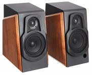
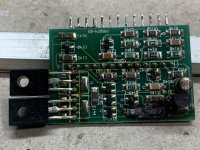
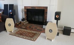
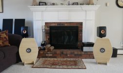
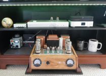
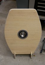
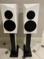
I built a pair of Zaph BAMTM using the sealed option (Link below) with a bit more internal volume as my first speaker build. The extra volume also allowed them to be floor standing. The second speaker is a mirror image of the first. I am very happy with how they perform and like the look of the aluminum cones against the dark walnut. Thanks to the designer! Standard MDF box with solid oiled walnut fronts. I would give my construction/woodwork a B as I rushed it a bit but I did learn a few things on the way. My homemade circle template for my router needs some refinement and I just used some rattle cans for the paint on the MDF. Some drilled Lexan was used for the crossover boards but I probably should of just used some 1/4" ply or hardboard. I have a Technics SU-7300 (48 watt at 4 ohms) powering them. I have a Onkyo TX-4500 II (60W at 8 ohms) that I want to build speakers for next. Musically, I am fairly eclectic and likely to follow a Rush album with Willie Nelson. Any suggestions for my next project? I am kind of leaning towards larger version of these MTMs that would maybe use the Dayton DA215 (8") or even the DA270 (10").

MTM1.jpgMTM2.jpg

http://zaphaudio.com/BAMTM.html

FS Satori Ara 2-Way Speakers SB ACOUSTICS Scan-Speak

Selling my beloved , FS Satori Ara 2-Way Speakers SB ACOUSTICS with upgraded Beryllium dome Tweeters

In case you are not aware of these speakers this is the link from MedisonSpeaker store but mine come with upgraded tweeters that below kit does not include.

Satori Ara 2-Way Speaker Kit- Pair

Purchased these from SB Acoustics Dealer during " 2018 AXPONA - Audio Expo North America" show April 2018.

SB Rep had Satori kit loaded with best components that they could showcase that inculcated upgraded Beryllium Dome Tweeters and top of the line crossover components. Matching Speaker Stands can be included in the price.

Price with Speaker Stands 1400 and 1300 without.
I'm in Chicago Area in case you'd like to pick it up.


Thanks!!!

Attachments

  • IMG_1427.jpg
    IMG_1427.jpg
    344.5 KB · Views: 206

Recommendations for a compact passive sub?

Hi, I want to buy the coat for the button, i.e. I have a Monacor SPH-250CTC dual voice coil 10" speaker, and looking for a suitable cabinet design.
My existing loudspeakers are dipoles that go down to about 80Hz. I want to build a passive subwoofer design with a single driver, connected the voice coils to both channels. Perhaps I could use a passive filter. The sensitivity should be about 85 dB/ 1W /1m. 35-40Hz lower cutoff is OK.
I was considering a modified Ripole, but that might not be the ideal choice. It should be compact anyway. What else do you recommend?

Increasing an Amp’s stability @ lower Ohmage - Output mosfets?

So I’ve been binging on amp repair vids on YT, etc and while watching a GZ 4K monoblock repair on BareVids (UK based dude who’s awesome) he mentioned “this amp runs 24n40f output mosfets which is a bit excessive on the voltage side, I could make this amp more stable at .5 ohm with 69n25’s but that would increase the cost blablabla ...”

After looking them up to see what the difference was the main spec difference I can see (I’m very layman lol) is the stock have a 400v 23a rating, the 69n25 he mentioned are 250v 69a rated. How do these specs effect output and how does changing them increase the stability of the amp when running a lower ohm load? And is that a common practice for increasing an amp’s stability at lower ohm loads? What else, if at all, would be needed for something like this?

I’d like to know the whats, how’s, why’s of it and really understand what’s happening here and why it would increase stability, that’s all he mentioned about it so I don’t know if there’s other small stuff needed as well (gate resistor change outs, etc) but I’m very interested, specifically for my 06ZX750.1 Power Supply repair I’m currently doing (which I’m writing up and plan on making a post about soon) and for my other personal amps.

I’m the type that likes to increase stats/specs if possible on any/all of my gear. One of the main goals when building&OC’n my gaming PCs for example 🙂 I realize this doesn’t inherently increase the output, which is not what I am after, just stability. Any and all types of info/insight would be much appreciated, thank you all!

🦾🤖🔊

Any Direct Drive ESL Amp projects someone could share?

There have been a few Direct Drive ESL Amp forays on this forum, but no completed projects posted. I am not interested in headphone ESL Amps.

Has anyone completed Neil S. McKean's ESL Amplifier?

If so, what power supply was used? Or where did you source one?

Were there any boards made for it?

Anyone update it?

Any other designs?

I understand that I am the beggar here, but if someone has made one, or another one, your experience posted here would be very helpful. If this should be in the amplifier section I am happy to move there.

Dual Port Tuning by taking advantage of the Floor/Wall near the port exit?

Hello! This is my first post here so i apologise if im posting this in the wrong spot.
I have a pretty wild question, but i think it's definitely something worth looking into. A few days ago I was scrolling through a forum somewhere and saw someone mention how it's important to keep the distance between the bass-reflex port and the wall its against (if it is against one in the first place) a minimum of the port diameter apart. so, for example, if i have a 2" port, my port exit and the wall/floor should be atleast 2 inches from eachother.

This got me thinking... if you were to place a subwoofer so that its port exited the box super close to the floor, is it possible to use the floor to "extend" the length of your port, and effectively lower the tuning of the enclosure?
Not only would this greatly reduce the required length of the actual tube section of the port, it would make it possible to tune smaller enclosures lower while maintaining a fixed box volume.
ALSO - it would mean you could have 2 different tuning frequencies to chose from, and all you have to do to switch between them is rotate the cabinet on a different side so the port faces into/away from a wall.

Can i get any insight into whether or not this is an actual thing that could work, and how it could be calculated?

Cheap DSP TSA1701, ADAU1701 DSPmini learning board or?

Hi all,
I need some cheap eq, bass enhancement etc. for my amp.
The ADAU1701 should fit the requirements and now I would have a question for you. What could sound better:
1. https://pl.aliexpress.com/item/32807805635.html
or
2. https://www.tinysineaudio.com/index.php?route=product/product&path=59_79&product_id=183

Unless there is something better for a comparable amount?

Thank you for your time 🙂

HiVi B3S + ScanSpeak 22W/8857T or XT25BG60-04 (or HiVi RT1C-A?) + Dayton RS52AN-8 + SS 22W

HiVi B3S + ScanSpeak 22W/8857T (or Fountek 88EX/89EX?)
Vifa XT25BG60-04 + Dayton RS52AN-8 + ScanSpeak 22W/8857T
HiVi RT1C-A + Dayton RS52AN-8 + ScanSpeak 22W/8857T

I figure with the HiVi B3S I can do a very simple x-over.
I would have to attenuate the XT25 or RT1C and RS52 a lot.

The B3S and 22W all I have to do is cap and coil at about 400 Hz and the Baffle step is taken care of.

I don't like dome tweeter or a lot of highs.
Except ribbons have okay highs I've noticed. And XT25 has zero "harshness" which "audiophiles" describe as dark? 😕
I describe it as functioning how it should for a specific purpose. I'm not trying to show off my high end shrill sound.
RT1C has excellent build quality.
XT25 is also good and ampslab has an x-over/design I can copy, woofer is different, but close enough for me.

RS52 come with metal grill and this is what I don't like building when I make speakers. The metal grill. Also metal (hex) grills look best to me.

https://www.parts-express.com/Peerless-XT25BG60-04-1-Dual-Ring-Radiator-Tweeter-264-1012
https://www.parts-express.com/Dayton-Audio-RS52AN-8-2-Reference-Aluminum-Dome-Midrange-285-020
https://www.madisoundspeakerstore.c...evelator-22w/8857t-00-8-woofer-aluminum-cone/
https://ampslab.com/falcon.htmhttps://ampslab.com/blog/2016/10/04/dayton-rs52an/https://ampslab.com/blog/2017/10/02/hivi-rt1c/
https://www.parts-express.com/HiVi-B3S-3-Shielded-Aluminum-Driver-Square-Frame-297-427
I already have a 3-way using:

Audiopur (I think) ribbon
Dayton RS52an-8
Dayton RS270S-8


It sounds pretty good. I copied Zaphs x-over with a few tweets:

http://www.zaphaudio.com/ZDT3.5.html
Music is good (via TV). Voices on TV are okay, but not great.

BTW I listened to Usher 9950 and 8948a off of my computer I bought from Joe D himself, very poor setup though and Bose 301.
The 301 sounded better to me personally (lol?). That's why I think I might like just 3 inch with SS 22W. Fountek EX88 or EX89 would be my first choice in 3 inch drivers though. I can always change it later, I guess. Fountek drivers seem to be scarce in the US. I try to build speakers for longevity, build quality and easy of driver replacement, also. I mount, finish and construct my speakers in my own way, if it matters.

Taking a MANGER MSW apart

Recently bought a pair of broken Manger MSW's and before I send them off to Manger to get them refurbished I thought it would be nice to take it apart.

First took the starformed damping off, then the complete membrane, underneath it was another damping, slightly thinner.
The membrane is made of 3 layers, 2 thin one's and a thicker one.

Do understand why it's costly to make such drivers.

Attachments

  • IMG_8075.jpg
    IMG_8075.jpg
    758.6 KB · Views: 804
  • IMG_8076.jpg
    IMG_8076.jpg
    887.4 KB · Views: 799
  • IMG_8077.jpg
    IMG_8077.jpg
    759.1 KB · Views: 780
  • IMG_8078.jpg
    IMG_8078.jpg
    764.1 KB · Views: 773
  • IMG_8079.jpg
    IMG_8079.jpg
    303 KB · Views: 826
  • IMG_8080.jpg
    IMG_8080.jpg
    737.4 KB · Views: 485
  • IMG_8081.jpg
    IMG_8081.jpg
    707.4 KB · Views: 438
  • IMG_8082.jpg
    IMG_8082.jpg
    777.1 KB · Views: 407
  • IMG_8083.jpg
    IMG_8083.jpg
    827.6 KB · Views: 415

Splicing JST XH 2.54 connectors

I'm building a system around an ADAU1701 2 in/4 out board. 2 of the outputs will go to RCAs for the subwoofer... I need the other 2 to split into a 4ch TPA3255 board for the full range speakers. Everything uses JST XH -2.54 3 pin connectors... what's the best + easiest way to split those connections into two? It doesn't look like the connectors can take more than one wire in each port.

Upgrading my old B&W 683

Hello,
For the last ten years, I've had a pair of B&W 683. The affection value is high, so upgrading them is very tempting.
I want to completely remove the existing tweeters and make a new front panel to remove the hole. I want to buy tweeters from B&W 700 series, and put them on top of the speakers. Additionally, the woofers must be replaced due to dents, considering B&W 603 woofers.

The FST mid-range both sounds and looks good, in my opinion. So they stay.

Is it possible? Reckon new crossovers are needed as well. Does anyone here know of one that can do the job, maybe adding a DSP? Or must I build one from scratch?
I am new to this, so please feel free to share your knowledge.

Is it ok to use 6SN7GT in place of 6SN7GTA/B ?

I have Darkvoice and Eufonika H5 and I am in USA (110/120V outlet). These amplifier are obviously made recently and most likely designed to take 450V 6SN7GTA/B driver tubes.

What would be the effect of using 6SN7GT tubes rated at 300V anode voltage instead of 6SN7GTA/B ? Shortened tube life, or worse, damage to the amplifiers ? I read somewhere that these are max rated limit and not the actual voltage in use.

In case it matters - I use these amplifiers not just for running headphones but also active speakers via RCA line out.

Thanks!

Dummy Load

:cop: This thread has been split from here - Autoranger for soundcards - at request. :cop:

Hi! My setup for measuring Power Amplifier THD 1. Load (4 Vishay Metal Film resistors) 2. Generator with battery 3. Relay attenuator with 1dB step 4. SC Asus Xonar Essense STX II

Dropbox - 20200828_002917.mp4 - Simplify your life

Attachments

  • 20200823_173120.jpg
    20200823_173120.jpg
    693.9 KB · Views: 1,427
  • 20181212_230623.jpg
    20181212_230623.jpg
    685.5 KB · Views: 1,265

ARC M100 regulator issue

I have a pair of M100's here that were in need of new tubes. They did play really fine after the retube for some time.
During the last power up, on of them started making wild popping sounds through the speaker and the regulator tube (6550) was sparking. Whoops.

Then the built in smoke came out before I could turn the amp off.
It was R124 that burned down. (All other associated resistors are fine)
Replaced it along with a fresh 6550 in the regulator position and tried again.
...to no avail.
When the amp powers on, there is a rattling sound from the output (speaker) even before the screen light turns on. (It will start as soon as the power tubes are somewhat warmed up.)
When turning it off, it will make oscillating noises.
I did try to replace the ecc81 and 7044 in the regulator as well but that did not help, just as replacing the output tubes (bias all the way down) did not help.

I know there are a couple of M100 experts over here. I would be grateful if one of you could chime in. Many thanks in advance.

Discrete Amplifier Resonance Peak with connected Load

Hello dear diyAudio people,

during the last months I 'designed' a discrete headphone amplifier. I designed some pcbs and tested them. The amplifier is okay for our needs and sounds somehow good enough. But I am wondering why there is a resonance peak in the frequency response at very high frequencies with a connected inductive load.

the figure below shows the amplifier schematics. It is inspired by the classical 'blameless amplifier' from Douglas Self.
headphoneamp-ltspice.png


Here you can see the frequency response of the amplifier with the inductance connected (the inductance is simulating our headphone load).

headphoneamp-inductive-load.png


However. I designed the amplifier without an inductive load in my mind and with the indicator shorted everything looks fine:


Headphoneamp-resistive-load.png


So now my question is. Does anyone how has plenty more amplifier knowledge than me, where this resonance peak is coming from within the circuit?
I mean at this point I have now idea 0.o

so thank you 🙂

Cheers
Gruftgrabbler

Attachments

  • Headphoneamp-resistive-load.png
    Headphoneamp-resistive-load.png
    152.5 KB · Views: 212

I didn't use quasi anechoic and I'm not sorry

Hi everyone,

So a long time ago I spent a lot of time here talking about making a 2 way using a 6.5" ScanSpeak Revalator. One of the controversial points was that as a short cut I did NOT use quasi-anechoic woofer measurements. In fact I deliberately measured with the cabinets in the room where I expected them to play.

I measured with OmniMic at 1M, using gated measurements through the crossover region.

I've moved about 3 times since then, bought a home and finally got down to measuring and the results in the bass were unexpectedly good. Given my experience I would encourage anyone building a 2-way to use a similar method. Am I being naive? Is there a part of the process that could have gone better which I got randomly lucky with?

I did use DSP to clip some peaks, and here is the average measurement from 3 points on my listening couch:


1641482489475.png


After these measurements were taken I did add a 4 dB boost shelf at 100Hz. There's a lot more detail in my blog post:

https://speakermakersjourney.blogspot.com/2021/12/room-speakers-eq.html
So my learned friends, given these results, and the reduction in complexity in attempting close mic measurements here, what's wrong with this short cut? Am I ruining the next generation of 2-way speaker builders by recommending this? Is this how you do it?

Best,

Erik

Elektro-optik connection: best of both worlds...

Hi guys,

I decided to open a thread for the best connection I've found between digital transport and DAC, which I consider the discovery of the decade. 😍

Elektro-optik is my invented name for -ECdesigns-' invention/discovery which he uses on his own Fractal DAC with his own digital protocol.

https://www.ecdesigns.nl/info/archive

It is simply using electric digital SPDIF output from the transport and the Toslink receiver from the periferal DAC by replacing the "receiving" connector of an electric digital cable for a 3mm Red LED (I use a mini-to-standard-toslink adapter to secure the LED and connect to Toslink in) AND also increasing the digital signal from stock output to 3V3 - 5V, depending on the transport's output circuit, for example by using the digital signal from the Optical Transmitter of an old DVD or by adding a digital buffer to your stock output.

Another solution for a usable digital signal is to mod a USB to SPDIF specialized external board by connecting the digital signal from the Optical Transmitter to the electric SPDIF out, which usually is 3V3. That would give you the best PC based sound, much better than the ADUM based connection I was using before, and more ellegant. I use modded USB cable with power separated from balanced signal...

A third solution relates to DACs which do not have Toslink receiver: use usual digital coaxial cable to connect transport to DAC and install a toslink receiver sub-circuit inside the box, to go to the digital input circuitry, after the input digital connector+Red LED assembly.

I have tried all of the above and all work OK. The total cost of the experiment should be under USD$10 for the best sound I have experienced. As per -ECdesigns'- explanation, it has the best of both systems with none of their side effects...

I attached some pictures and diagram explaining the process.
I hope you like it.

Cheers,
M.

Attachments

  • Electrooptic (1).JPG
    Electrooptic (1).JPG
    273.5 KB · Views: 144
  • Electrooptic (2).jpg
    Electrooptic (2).jpg
    324.2 KB · Views: 141
  • Electrooptic (3).JPG
    Electrooptic (3).JPG
    419.1 KB · Views: 143
  • Electrooptic (4).JPG
    Electrooptic (4).JPG
    257.6 KB · Views: 128
  • Electrooptic (5).JPG
    Electrooptic (5).JPG
    428.1 KB · Views: 137
  • Electrooptic (7).JPG
    Electrooptic (7).JPG
    410.5 KB · Views: 130
  • Electrooptic (9).JPG
    Electrooptic (9).JPG
    301.7 KB · Views: 139
  • ELECTROOPTIC LINK buffer2.jpg
    ELECTROOPTIC LINK buffer2.jpg
    218.7 KB · Views: 143
  • ELECTROOPTIC LINK.png
    ELECTROOPTIC LINK.png
    9.7 KB · Views: 157
  • ELECTROOPTIC LINK2.png
    ELECTROOPTIC LINK2.png
    9.9 KB · Views: 144
  • electroptic internal RECEIVER DETAIL.jpg
    electroptic internal RECEIVER DETAIL.jpg
    318.1 KB · Views: 150
  • USB to ELEKTROOPTIK.jpg
    USB to ELEKTROOPTIK.jpg
    190.7 KB · Views: 151

NAD C356BEE Relay clicks

Hello.
NAD C356BEE integrated amplifier.

if it is turned off for a long time (1 hour....for example) from the outlet or rear switch when I turn it on, the relay RL311 on tone board clicks at a frequency of 2 times per second for about 20 seconds, the orange led "standby" flash too.
Amplifier cannot be turned on at this time. After 20...25 seconds Amplifier is on standby mode and can power on normally.

If it is in sleep mode all time then it turns on normally.
When plugged into an outlet.

SM

https://www.manualslib.com/manual/1356224/Nad-C-356bee.html

fairchild find?

hi, i just found these little black boxes full of semi's that i remember buying at a yard sale when i was a kid - mostly because i think they "looked expensive"

anyways, in each box there are:

1 x AY9171
1 x AY8171
1 x 2N3638A
1 x 2N3643
1 x SE4010
1 x 2N4250
1 x 2N3565

and i have two matching boxes...

the base of the box states that the AY9171 is PNP and the AY8171 is NPN and they are rated at 35W Max. Power T.C 25'C

basically - what can i do with these?

i assume it woudl make a great stereo 35W amplifier module, but i have no schematic, nor do i know how to create one?

any advice woudl be good,

if they are junk - i will forget about it, but if they are not 'junk', it could be a worthwhile project?

attached is pic

Attachments

  • fairchild001.jpg
    fairchild001.jpg
    78.2 KB · Views: 644

Crossover upgrade in a Jeff Bagby Auricle

Hello, I'm new to this forum, although I've read many posts here over the past several months and learned a lot. Having built most of my power cables and interconnects, I decided last fall to build a pair of Jeff Bagby designed Auricles, through Meniscus. At the time I wasn't very knowledgeable about crossover components, and just went with the highest quality offerings Meniscus listed. Since then, and being an obsessive optimizer, I've been reading up on caps and inductors, in order to gain a more intuitive grasp of their functions. Wow, rabbit hole. Now I'm seriously considering swapping out the caps and coils on these speakers. I know I"m just jumping in hard here, but I'll describe the current configuration so anyone who is interested has the info.

The Auricles use RAAL 70-20 tweeters and Satori 6.5" midwoofers. I've built the boxes quite robustly, with a 1.5" baffle and thick damping material on the inside walls of the cabinets, which are front ported. Corssovers are as follows: Tweeter - 6.8mF Mundorf Supreme (no oil) cap, .68mH 20 ga basic wire coil inductor, and a couple of mundorf resistors to pad the level a bit. Woofer uses a Clarity Cap 4.7mF cap, and 3mH 14 ga wire coil. Pretty simple crossovers as these drivers integrate very smoothly without too much fuss. Crossover point is 1800 hz.

I'm wondering first of all, if it would be worth messing with the Satori board, and if so whether to address the inductor, the cap, or both? I'm pretty confident swapping out the parts on the RAAL board will open things up even further, but not sure about the woofer.

Right now the candidates for tweeter caps are VCap ODAM, or either Mundorf Supreme silver/oil or Mundorf Supreme Silver/Gold/Oil (EVO or Classic). The inductor would be a Mundorf copper ribbon. If I mess with the woofer, I'd probably do something similar.

If you ask me what my design goals are, I can't answer in the way I'd like to as I have nothing to compare these speakers to in my system except the last pair which were ELAC UB52s, and the Auricles are in a different league. They sound absolutely fabulous, but I really think I left a lot on the table when I just went with Meniscus' default components. I've seen what something as small as a binding post swap can do, and my system is decent enough to hear the rewards of upgrades, to a point. Right now I'm using a Schiit Aegir in stereo but in the near future I'll either add another and go monoblocks, or swap out for another class A amp altogether. I really think these Auricles are something special, and that it's worth putting the extra shine to them if it will make a difference.

Any ideas would be greatly appreciated, thank you!

FS: Maplenoll Ariadne Platter, Air Bearing, and Air Pump

Maplenoll Ariadne platter, air bearing for platter, and air pump, with hardware. Sale by original owner. Items were purchased in 1990 with turntable. Items were later removed and replaced when turntable was upgraded with different parts. Excellent condition. Shipping from Northern California to within USA. $200 or best reasonable offer plus shipping.

Thanks,

Gary

Attachments

  • MVIMG_20180115_223954.jpg
    MVIMG_20180115_223954.jpg
    15.2 KB · Views: 539
  • MVIMG_20180115_223829.jpg
    MVIMG_20180115_223829.jpg
    17.9 KB · Views: 509
  • MVIMG_20180115_223258.jpg
    MVIMG_20180115_223258.jpg
    18.2 KB · Views: 514
  • MVIMG_20180115_222933.jpg
    MVIMG_20180115_222933.jpg
    23.9 KB · Views: 527
  • MVIMG_20180115_221922.jpg
    MVIMG_20180115_221922.jpg
    35.3 KB · Views: 539

300b amp with one silent chanel

Hi guys,
I have this 20 years old 300b single ended amp. It works perfectly in the right side but the left is completely dead. I have tried to find the error but no luck so far. I have found an irregularity in the place marked with blue in the schematic. The working channel has apron. 150V as supposed but the silent channel has apron. -50V.

I cannot figure out why the voltage both are dropped and reversed polarity. Do any one have some tips on where this fault might be located?

Regards Daniel

300b amp.jpg

5V regulated supply

I'm in the journey of building my first tube amplifier. Well I'm rather close to the long-awaited end as everything's been soldered and tested (and it sounds sweet). The only thing I haven't managed to sort out is the heating for the power triode. The tube being a 300b requires a 5V at 1.3A or so current source, and I've decided to go with DC. I've bought several regulators (LT1805, LT1805-5IT, LM7805) and never had any luck: some would produce too low of a voltage (either due to overloading or low input voltage i believe), some would work briefly and then power off because of overheating, still producing too low of a voltage. The best I've been able to accomplish is ~4.3v with the LM7805 which still overheats and powers off. Now after a month or two of thinkering I've decided it's time to give up playing the guessing game and ask more knowledgeable people for a design.

In my current setup I take the 6.3V@4A secondary of my transformer (which powers two 6J5 using up about 0.6A of the total) and rectify it via a GBU4B, then filter it trough a 6800uF capacitor and feed it to one of the tested regulators. The rectified voltage at the filter cap is lower than what I expected (which may be the root cause for all my problems) ranging beetween 6.5-7.2 depending on the load. I'm afraid I may be putting too much stress on this winding and therefore getting a low rectified voltage, tough I've never seen the AC reading drop below (a very steady) 6.3V.

Things I though might help:
  • Get some more efficient diodes (please leave suggestions if you have any)
  • Use another small filament transformer just for this purpuse (I do have some space left to fit it)
  • Add a heatsink for whatever regulator I end up using (I figure a 8°C/W one should be enough?)
Before I do any of that I'd really appreciate the opinion of more experienced builders. I'm open to any sort of change to get this thing working reliably. Bonus points if any of the chips or the transformer can be reused but also if the circuit is exceptionally simple.

Am I the only one notice this on Wima MKP10 ? - Re-burn In

I apologoze if this has been asked before but I searched and did not find discussion about this.

I have been using Wima MKP10 on a couple of tube preamps that I built. I can tell those caps need some time to burn in to sound good.

One of my preamps was sitting in the shelf for a while and I just pulled it out and use it again. I thought the WIMA inside was already burned in but the sound at first was really dry and grainy like brand new WIMA. I let it played for a while (probably 2 hours) and the familiar sound begin to come back.

So, if a WIMA (or generally a film cap) has been burned in but then sitting for a while, a re-burn in period is needed ?

Prism dScope Seriess III has BTL + DC issues?

I'm experiencing issues with the dScope III when connected to an (automotive) BTL amplifier (as are commonly used in car radio's). The problem seems to be that the outputs of these units have a DC voltage of about 6-7 Volts on both speaker wires (hot and cold wire) compared to the power- and input ground. Regardless of the analyzers' output GND setting (unbalanced, floating, etc.) the analyzer registers extreme levels of distortion, but only up until a certain level. At some point the input attenuator switches (audibly) and the measured signal becomes perfectly normal. When I decrease the level again the attenuator switches back at a lower point (there is some overlap/hysteresis) and the signal get's distorted again as soon as the attenuator switches range.

So there is a kind of "grey zone" in the input level; depening on whether I am increasing or decrasing the signal level the attenuator can be in 2 different ranges for the exact same input level. In this grey zone I am measuring the same signal at the exact same level with either ~0,01% distortion OR ~8% distortion, depening on the range the attenuator is in.

I assumed a defect attenuator so I've exchanged the unit for a different one from our supplier but the issue remained exactly the same. Both units tested OK using the self-test macro. We tried setting the input highpass filter (in the software) to DC block but that didn't help either. Only if we add two bipolar capacitors in series with the test leads (to block the DC) can we measure the entire level range without issues.

Since we have 2 units with the exact same issue I was wondering wether this was actually a "feature of the product" or if maybe I'm doing something wrong. Hoping you guys have experience.

dScope_1.jpg
dScope_2.jpg

FS: NOS Sanken MT200

Hi,

I’m selling 12pairs Sanken 2sc2922/2sa1216 MT200 transistors,
I have these for about 10 years. These 24 pieces have never been soldered. P’s and N’s are from same batch.

Price: €150 for the entire lot.

If interested, send me a PM.

Attachments

  • B1DBD880-38C4-4876-868D-B71F065E3493.jpeg
    B1DBD880-38C4-4876-868D-B71F065E3493.jpeg
    376.7 KB · Views: 453
  • D7D01426-D1BD-4161-B182-5A6CFE1D7163.jpeg
    D7D01426-D1BD-4161-B182-5A6CFE1D7163.jpeg
    401.7 KB · Views: 393

How build 8 ohm center channel with 8ohm drivers

Hi,

I these days I'am planning to build a home theatre speakers 5.1 ( 2 front, 2 rear, 1 center)

My plan is use:

Woofer: 1 x Seas L18RNXP ( 8 ohm)
http://www.seas.no/index.php?option...le&id=75:h1224-08-l18rnxp&catid=44&Itemid=461
Tweeter: 1 x Visaton ke 25 ( 8 ohm)
https://www.visaton.de/en/products/drivers/dome-tweeters/ke-25-sc-8-ohm
with crossover frequency of 2.2 Khz for all boxs (front, rear and center).

The problem is the center channel where I need 2 x Seas L18RNXP and the impedence will be 4 ohm and not 8 ohm like I need.

Francally I don't known how solve this problem becouse I like that all boxs produce the some sound if is possible.

Theorically I can insert a 4 ohm resistor in series between the two woofer and the crossover, but I don't like this type of solution.

Another solution can be use only one Seas L18RNXP and put the center channel in vertical, but I never seen a solution like this.

Can you please suggest me a better solution ?

Thanks !!

CD puzzle

I recently bought a 2-disc CD album. Popped them into my Sony multidisc carousel and find that one disc plays fine but the other is really dreadful. On first couple of attempts it just sort of "jitters". I tried it in different positions in the player and no difference. No scratches or visible damage at all. The seller claims that he tests all the CDs he sells on a PC before he posts them. I tried the dodgy disc on my desktop PC and sure enough, it plays without issue. I have about 350 CDs that play well on the Sony player but this is the first disc that doesn't work.

Why might this be? Manufacturing defect? Player laser out of alignment? Something else?

"Updaing" an integrated amplifier

Hi All,

I have an Atoll IN80se integrated amplifier that I wish to "refresh" few of it's electronic components and I would like to hear your suggestions and/or ideas:
IMG_1195.jpg

IMG_1201.jpg


1. it's bridge rectifier is a monolithic 8A cheap looking bridge rectifier and I would like to replace it with a better quality 25A one, prefer to stay with monolithic type and not using separate diodes, any suggestions for a good quality monolithic bridge rectifier?

IMG_1205.jpg


2. would like to replace the 4x 6,800uF 63V Jamicon (marked green) main capacitors with 10,000uF or a bit higher value ones, restricted to 30mm diameter and 50mm height, was looking for a KEMET ALC10S series or Kendeil K05 but couldn't find any in stock (online) the only one I could find is the Cornell Dublier SLPX series, is it good for this purpose? do you know any other better capacitor that will fit? looking to spend about 10Euros each.


3. I would like to change the 1uF input capacitors (currently cheap MKP, marked red) with a highr quality one, looking to spend no more than about 12Euros for each.


IMG_1184.jpg


4. Change the cheap 10x Jamicon 220uF 63V capacitors (marked yellow)next to the TIP31C bipolar transistors for a higher quality ones, any suggestions for better capacitors?


IMG_1191.jpg


I'll appreciate any suggestion, idea or comment.
Thanks

Attachments

  • IMG_1184.jpg
    IMG_1184.jpg
    170.2 KB · Views: 232

David’s Basment rooom setup DIY progress

Staring to re do my basement. My room from 3 sides is all concrete and back opens up to 2 closets in the back and side room that’s being used as a storage . My main goal is to limit vibrations and to remove room effect es much as possible. For base I decided not to fight it and keep rear closets and extra room to act as additional sound capture , closets will have mineral wool . I’ll post progress and pics as I go with questions .

Good way to mount single-pin components for easy replacement?

I'm working on a tube amp where I am interested in potentially changing tubes in the future. This would require swapping a few resistors around. The manual for my kit indicates that the PCB is thick and makes it hard to remove components. I'm wondering if there is some type of socket or disconnect that would allow me to swap resistors without having to desolder them?

GB: AYA II TDA1541A DAC (2014 Edition) PCB or Kit

GB: AYA II DS TDA1541A DAC (2015 Edition) PCB or Kit

Until Novemeber 7, 2015: Third run is now available.🙂
Its called AYA II DS, with synchronous DEM clocking circuit integrated.
Please see details here:
AYA II DS, DIY edition - Audial online topic

----------

Here is a group buy opportunity for the PCB or kit of the Audial AYA II TDA1541A DAC (2014 DIY Edition).

Please click to this sign up page on Pedja Rogic's website for the information on pricing and description, and post your questions and comment for Pedja there.

AYA II 2014 DIY edition interest check - Audial online topic

This GB project originated from:

Any good TDA1541A DAC kit?
http://www.diyaudio.com/forums/digi...ny-good-tda1541a-dac-kit-102.html#post3921439

Question about shared resistor values when using different types of input/output tubes (Aikido Octal Line Stage)

I'm looking at my tube options for this Aikido line stage project. The schematic and suitable tubes list are attached. My question is this: If I want to use different tubes for gain and output, how do I select the optimal value for R10? It isn't clear to me how this value affects the rest of the circuit, beyond the suggested values provided.

EDIT: The manual describe the relationship between R10 and R9 as being dependent on the mu of the tubes being used, via the following formula: R10 = R9((mu − 2)/(mu + 2)). That's great and all, but it does not help me understand the calculation when tubes with different mu values are used. Should I simply average them together and then adjust manually for least noise?

Anechoic listening room?

Not sure if this is the right place.
appologies if so.

But if you could make an anechoic or close too room as a listening room (for loudspeakers naturally)
would that be recommended?
i cant seem to find anything, or even any "reviews" of listening to loudspeakers in an anechoic chamber?
(granted it was a limited search, easier to go to the sauce!)

have any of you experienced this?

im just really curious, music from a linear projection, with Thumpy bass?
seems very interesting.
numerous channels?

things could get weird!

MIRAND AUDIO TSSA V1. 8

Nice build truly good sounding power amp with mirand audio module ples thel supreme regulators, kendeil 13000uf 100v capacitors, 500watt toroid, dc blocker and soft start. Biased to 400mA and hase about 40-50 watt chanel 8R.the amp us build with good materials and is about 15kg heavy. Price would be 600 euro plus shipping inside EU. More info on request.

Attachments

  • IMG_20220122_135849.jpg
    IMG_20220122_135849.jpg
    456.6 KB · Views: 196
  • IMG_20220122_135857.jpg
    IMG_20220122_135857.jpg
    436.6 KB · Views: 251
  • IMG_20220122_135916.jpg
    IMG_20220122_135916.jpg
    176.8 KB · Views: 195

NOVA JH-2000 Tube amp EL84

For sale verry good tube amp from Germany in original condition with 4 x el84 pro chanel plus 6cg7 for driver with volume pot. Good quality build 23kg of weight and sounds fantastic without hiss or noise, only the psu transformer hase a litle mehanical buzz. The el84 tubes are JJ, the 6cg7 are golden dragon. Price would be 550 euro plus shipping inside EU. More info on request.

Attachments

  • IMG_20220102_185410.jpg
    IMG_20220102_185410.jpg
    412.1 KB · Views: 276
  • IMG_20220102_185403.jpg
    IMG_20220102_185403.jpg
    388.6 KB · Views: 229

LTSPICE IRF820 model

Hi. Does anyone can help me using this model on LTSPICE? It doesn´t work...

.subckt IRF820 D G S
.model mosfet NMOS( LEVEL=7 VTO=3.81 RS=0.06816 KP=2.149 RD=2.3567 TC1RD=0.0127 RG=15 IS=1e-36
+ CGDMAX=1.00E-09 CGDMIN=1.06E-11 XG2CGD=0.5 XG1CGD=0.1 CBD=6.97E-11 VTCGD=0)
.model diode D( IS=3.50e-13 RS=0.0343 TT=1.657e-06)
M1 D G S S mosfet
D1 S D Diode
Cgs G S 3.18E-10
.ends

I´m new to all this spice things, but I don´t have any problems making tube models work. I just included a file called tubes.inc, and I call it with the .inc command from the schematic, and it works great. So, I thought I could just creat a file called mosfets.inc and do the same, you see? But for some reason it won´t work.

Anyway, there´s also this one:

.SUBCKT XIRF820 10 20 40 40
M1 1 2 3 3 DMOS L=1U W=1U
RD 10 1 1.42
RS 30 3 76M
RG 20 2 60
CGS 2 3 323P
EGD 12 0 2 1 1
VFB 14 0 0
FFB 2 1 VFB 1
CGD 13 14 475P
R1 13 0 1
D1 12 13 DLIM
DDG 15 14 DCGD
R2 12 15 1
D2 15 0 DLIM
DSD 3 10 DSUB
LS 30 40 7.5N
.MODEL DMOS NMOS (LEVEL=3 THETA=60M VMAX=1.04MEG ETA=2M VTO=3 KP=1.3)
.MODEL DCGD D (CJO=475P VJ=.6 M=.68)
.MODEL DSUB D (IS=10.3N N=1.5 RS=.34 BV=500 CJO=236P VJ=.8 M=.42 TT=260N)
.MODEL DLIM D (IS=100U)
.ENDS XIRF820

Thanks for any help!

For Sale Holton Audio Amp Kit - Unused

Hello,

Up for sale are a complete (no chassis) kit of parts to construct a Holton Audio 300W amp. Parts include:

(2) HPA-NXL500 Amplifier modules configured by Anthony as 250-300W amps with 4 mosfets each channel
(2) HPA-NXVPSU Power Supply PCBs without filter capacitors
(1) AC Mains Controller
(2) Speaker Protection PCBs
(2) Toroidy Audio Supreme 300VA 230V primary and 2x45V secondary with mounting plates

Asking EUR 600 for the lot.

IMG_3599.jpg


IMG_3600.jpg


I purchased these late 2020 with better intentions. The parts have remained packed as received - not modified, installed or used in any way.

Located in Germany. Buyer pays actual shipping costs in addition.


Best,
Mike

What should the normal THD+N of PCM1794 be?

我根据 1794 年的手册制作了一个 PCB。IV和LPF都使用手册中的原始电路,并以单声道模式运行。左右通道采用8x TPS7A系列超低噪声LDO芯片,分别负责+3.3V、+5V、+15V和-15V。音频通道采用4层PCB,0.1%精密薄膜电阻和NPO滤波电容。通过合理的布局和去耦,得到了非常漂亮的信噪比和博士。这是我第一次接触音频测量。我使用的是e1da ADC,它具有与ap555相同的精度,因此测量结果更可靠。这次我做得好吗?也许它不能与ESS或AKM芯片相提并论,但在同一个PCM芯片中?

我注意到dddac在论坛中使用了nos1794。该方案的参数是否足够低

Attachments

  • QQ截图20220122135323.jpg
    QQ截图20220122135323.jpg
    197.8 KB · Views: 192

Open Baffle Speakers DONE!

OH MY!!!! Just finished the open baffle speakers. Hooked them up to my main system. Turned it on and nearly fell over on the floor.....Holy Schiit! do they sound great! Using the B&W ASW608 subwoofer.....The spacialness is amazing, even without a hard wall behind them. My living room is very heavily damped so the bit of extended highs that the Tang Band speakers exhibit is very welcomed......These speakers have a total cost of $225 for the pair.....The plywood is extremely nice bamboo plywood from Lowes ($21 for 2' X 4' X 1/2", Drivers are $79 each, misc connectors etc rounds it out.......OK, they are not Magnapan MMGs or KEF LS50 Metas...But they absolutly bury and of my under $1000 speakers....As long as you use a subwoofer. As you can imagine bass rolls off fast around 100Hz.....I'll do some measuring next week and report.

Attachments

  • P1040803 (2).JPG
    P1040803 (2).JPG
    162.4 KB · Views: 274
  • P1040804 (2).JPG
    P1040804 (2).JPG
    179.8 KB · Views: 234
  • P1040805 (2).JPG
    P1040805 (2).JPG
    221.9 KB · Views: 254
  • P1040806.JPG
    P1040806.JPG
    265.1 KB · Views: 275
  • P1040807 (2).JPG
    P1040807 (2).JPG
    103 KB · Views: 291
  • P1040808 (2).JPG
    P1040808 (2).JPG
    277.2 KB · Views: 294
  • P1040809 (2).JPG
    P1040809 (2).JPG
    261.8 KB · Views: 286
  • P1040810 (2).JPG
    P1040810 (2).JPG
    331.8 KB · Views: 312
  • P1040793 (2).JPG
    P1040793 (2).JPG
    364.3 KB · Views: 299

BREEZE Audio : New Fully balanced XLR TPA3255 Amplifier / DIP8 op amps

Hi amigos )

As promised, I am sharing some spec and pictures about the new Breeze Audio TPA3255 amplifier.
This is the only full balanced finished amp that I found for less than $200 )

The amp comes in an black aluminum case of modest size but seems robust however.
In the front plate you will find the RCA / XLR inputs selector with that motorized volume pot and the ON/OFF switch
I am still wondering why spending so much money on a motorized potentiometer since the amp doesn't have a remote...

The speakers banana connectors are OK and seem solid.
The XLR connectors are OK as well with a secure clip. RCA inputs are conventional
I do not observe any play on the volume knob and nothing to complain with.
You can see that the inside speaker cables and PSU to module cables are directly soldered to the PCB. (no JST connector here)

Safety is important: the amplifier is properly grounded ) Nice for a Chinese amp. )
BUT :the neutral and the phase were reversed... I corrected it )

Little mod I made :

  • Update OP amps > OPA2210 (crazy op amps, give a try really !)
  • Twisted the 220V cables
  • Reversed the Neutral / Phase properly
  • Insulated the PSU to module 36V cable
  • added ferrites on the speaker cables
  • added copper film to the transformer core

Listening test still in progress. But after 1 hour I can say; dead silence (even with my ears glued to the speakers) I only tested the XLR inputs with my Gustard A18 DAC.
The OPA2210 definitely worth trying! as good of the OPA1656 in term of Soundstage but with the best of the OPA1692. This super BETA Bipolar OP amps is really fast with a very low DC offset. The amplifier sounds great and very loud with the volume @ 30%. I tried to turn the volume @Max, it remains ultra silent, good point here.
For the rest, I can't say too much more, it's too early....


TPA3255 MODULE :

WIMA MKS Caps (next to the volume pot) = 2U2J63 2.2uf / 63V
Electrolytic SMD Caps next to the OP amps = 220uf / 16V
Panasonic FC caps between inductors : 50V / 220uf
Switching Voltage Regulator = TI LM2575S-12
Electrolytic SMD Caps next to the Voltage regulator = 220uf / 16V
Power caps next to XLR inputs : 470uf / 50V
Polypropylene Film Capacitors : MKP10 / 0.1-250
Hongfa Relay = HFD4 / 5-S
Sagami Inductors
Volume pot : Motorized Quadrirotor RK168 100K 100KAX4

PSU :

SMPS PSU 36V / 9.5A @342W
Epsilon 400uf / 400V x2
United Chemicon 1000uf / 50V x 4
Stable @ multimeter !


  • Like
Reactions: Bruveiker

Great sound from PA Coaxial?

I'm going to build moderate size loudspeakers for my TV systems 🙂
I want wide sweet spot so I thing about PA Coaxial 10" or 12".
I like Dynamikks Monitor series - wonder which BMS Coaxial are they use?
MONITOR Serie - dynamikks
Budget is about 1000Euro/two speakers (max).
I don't know what is better - coaxial with horn or without horn?
My types:
Beyma 12XA30/Nd
Beyma 12CXA400N
Fatail Pro 10HX230/12HX230
BMS 10"-12" (BMS 12CN680L is a bit too expensive but maybe sooo good)

TU-8200 / TU-8800 OutPUT Transformer


I have a lot of NEW Output transfromers from stock TU-8200 and TU-8800 amp.
I will give these output transformers away.
Condition:
As long as you can show me you have donated $40 (a pair of TU-8200 OPT) or $60 (a pair of TU-8800 OPT) to any children's hospital or any organization (in any country) to

SUPPORT CANCER RESEARCH.....​

We can work out the shipping cost from Canada..

  • Locked
Seller Experience (Nightmare)

if u decide to go down the mod road, where you buy expensive caps and such from plays in a big part in deciding if this journey will be a pleasant or nighmarish one.

try to buy locally, or through ebay or aliexpress, e.g. rather than from a seller directly (no mediating body) online.

my recent totally bad experience with the arrogant and obnoxious HIFICOLLECTIVE in the UK illustrates this :
first their website can't process my order, despite numerous attempts. no apologies from seller.

then the very ethical sellers ask for your credit card number over phone
you refuse. when website gets fixed (this one issue anyway, their site has several other issues, i learned later) they wont inform you. you gotta keep asking.

asking them advice gets you curt replies and then radio silence, they went on holiday without telling you.

you finally order from them but their website screws up your address (can't do auto-fill unlike professional websites like ebay or aliexpress) so the parcel never gets to you, but returned to seller - TWICE, geniuses keep sending it back to me despite knowing the address is wrong.

seller will not refund and blames you for screwing up the order. lies about not receiving the parcel.

finally after sending many angry emails to seller, and threatening legal action, seller relents and refunds u but MINUS $45 for the shipping back and forth which was ENTIRELY THEIR FAULT

so perhaps you spend a grand or 2 at a time every time you order from hificollective, and get treated like royalty, but if not my advice is dont buy from sellers like HIFICOLLECTIVE, UK

arrogant unrepentant selfish pricks crooks

oh yes, and fwiw, for beginners like me, do try NOS capacitors first, they sound as good as mundorf/jensen/duelund etc
at fraction of the costs, imo!

Beyma 15MC700Nd as 15P80ND (V2) replacement ?

I've designed 2 boxes for the Beyma 15P80ND, in its (i think), second iteration (06/2014):
- 15P80ND (V2) Technical file

The baffle was designed for this version exact dimensions:

JZ8dt03.png


  • Inner baffle (1) (3) = 388 mm
  • Outer baffle (2) (4) = 349.5 mm

It seems that around 11/2020, Beyma released a V3 version:
- Beyma 15P80ND V3 Technical file

The T/S parameters, as well as the dimensions are different for V3, and more specifically, the inner baffle (1) , that now is 352mm:

7nd08gg.png


Moreover, the price for the Beyma 15P80ND has increased 100€ per unit, from 300€ to 400€.

The only alternative with the exact dimensions of the Beyma 15P80ND (V2) is the Beyma 15MC700Nd.
- Beyma 15MC700Nd technical file

ZWEDikT.png


The Beyma 15MC700Nd is also cheaper (282€ vs 400).

This driver will cover the frequencies bellow 350/300Hz.

I tried to model the driver, but either i've made a mistake, or the T/S parameters from the technical file aren't correct (file attached).
I can't find any feedback for the Beyma 15MC700Nd, except their introduction in AudioXpress.

Based on the above, is the Beyma 15MC700Nd a good replacement?

PS: The boxes are already built!

Attachments

DIYSG Apollo MT design

The Apollo MTM cabinet is the perfect overall size that I'm looking for, however the cost is a bit more than I was looking to spend.

My thoughts are to buy the Apollo MT kit, but build it into a 1 cu ft cabinet with about the same dimensions as the MTM version, tuned to about 35 hz (2" Precision Port at ~5.5" long). Given the 7" Anarchy specs/capabilities, is this a good idea or is that too much volume for the one woofer? Probably of important note, is that I will not run it full range at high volume ever. When I'm looking to crank, I will employ a separate sub crossed at 50hz.

Uneven High Rail Voltage

Good Day. A friend bought a used, repaired amplifier and brought it to me to check out before use. It appears that the outputs were replaced and the low side drivers on the board were replaced also, but instead of MPSA56, they used MPSW56.

The problem I am seeing is that when powered up, the +rail jumps up to +77v and then settles at +74v, while the -rail settles at -60v without any RCAs plugged in. As soon as the RCAs are plugged in, the +rail jumps to +85v, and the -rail goes to -69v. The rail caps in this amplifier are 3300uf80v.

This is all being checked on the bench with a 12A power supply that outputs 13.7v with no load. The voltage measurements are taken with a voltmeter referenced to input GND. The scope shots are referenced to GND input with the probe set to 10x. Is there something I need to do to this amplifier for safe operation?

Attachments

  • IMG_20220121_134757.jpg
    IMG_20220121_134757.jpg
    752.4 KB · Views: 93
  • IMG_20220121_134814.jpg
    IMG_20220121_134814.jpg
    634.5 KB · Views: 89
  • IMG_20220121_134809.jpg
    IMG_20220121_134809.jpg
    443.9 KB · Views: 90
  • IMG_20220121_140119__01__01.jpg
    IMG_20220121_140119__01__01.jpg
    457.8 KB · Views: 93
  • IMG_20220121_140150__01.jpg
    IMG_20220121_140150__01.jpg
    535.9 KB · Views: 93
Projects by fanatics, for fanatics
Get answers and advice for everyone wanting to learn the art of audio.
Join the Community
507,772
Members
7,887,787
Messages

Filter

Forum Statistics

Threads
406,200
Messages
7,887,787
Members
507,772
Latest member
Hypertone