What is the best way to test the LT4320, i burned 2 of the 4 Mosfets by mistake and would like the check the LT4320..Thanks for help
Not sure how to check the correct function of the little IC - it's probably contained in the pages of operating information somewhere but you need some knowledge about how to make it function
Now, assuming for a moment that you just inserted the fets in back-to-front (a simple mistake that I'm surprised I haven't made myself !), then the gate would be getting the ac input waveform, yes? And the fet wouldn't like that much, eh!
But the IC wouldn't actually be stressed at all so should have survived the mishap okay so I'd just replace the faulty fets and see what happens
If you have a CRO, you can see the waveform of the rectified voltage into the power supply capacitor.
One of the guys made the mistake of turning on the power without inserting the IC in the socket and this also blew the fets but not the chip itself
Maybe someone else with first hand experience will chime in too
No other way than replacing the mosfets and keeping fingers crossed. Fairly cheap mosfets can be used for the purpose. Btw you can check operation using a dc lab supply and make use of its current limiting.
Just follow through the current paths to the chip (ac input) and the path of the fet currents on the circuit diagram and you'll see what happens when the fets are put in 'back-to-front' hence the idea to replace just the fets.
Not sure what voltage/current you are using for the amp but still quite a fewfets with suitable parameters available at reasonable prices - you don't actually need fets that exhibit less than 5mR unless passing really high current, >10mR is okay ...
What are you using the lt4320 chip for? If you are using 2 if them for a dual rail supply, are both set of fets inserted incorrectly?
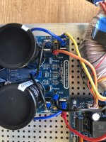
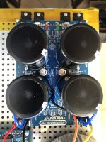
Thanks, i have finish the PSU that i will use to power the Amplifiers that i will test or fix. i can adjust the output from 45Vdc to 75Vdc.
I have also the choice for input, with Rectifier diodes (BYV42) or the ideal diode bridge controller (LT4320). The PSU work perfectly with one or other input. During the test I burned 2 Mosfets and 2 LT4320..it does happen sometime. Now i am not sure with one LT 4320, i don't want to destroy an other Mosfet, so it is why i would like to know if someone know how to test the LT without connections with the Mosfets
I have also the choice for input, with Rectifier diodes (BYV42) or the ideal diode bridge controller (LT4320). The PSU work perfectly with one or other input. During the test I burned 2 Mosfets and 2 LT4320..it does happen sometime. Now i am not sure with one LT 4320, i don't want to destroy an other Mosfet, so it is why i would like to know if someone know how to test the LT without connections with the Mosfets
Attachments

From my perspective, if you're going to be using the rails up to 75v in some higher power amplifier, I'd just use the diodes or an IXY block bridge - the LT4320 has an upper voltage limit of 72v - if you do want to continue with the higher voltage synchronous rectifier, I suggest you get a factory built one from 'the man' in Europe, not cheap but fully tested at much 'higher voltages'
- Home
- Amplifiers
- Power Supplies
- Would like to check LT4320.....