MPF102

FET-preamp-compressed.jpg


MIC-preamp-compressed.jpg


Hello all. I wanted to fool around with a jfet tone control. I am just only starting out with these types of circuits so would like to request some help please. Are either of these two circuits suitable for inserting into a two-way passive tone control. That's all I am after, really. Just a simple jfet based bass and treble control

Also, is it possible to build a mixer stage using either circuit to mix three of those "toned" mono channels together and then send to a quality pc type 2.1 active speakers? That would be a bonus

It appears that all parts that I will require for this design are available in my local Jaycar electronics shop. They don't have any other audio jfets

Please recommend a two-way tone schematic that I can use with one of the two circuit images. This is for my daughter and friend to practice bass, guitar and singing. I am a bit short of time as today is Wednesday, and they start their lessons on Friday. I have something they can use if I don't get this ready on time. I want to make something like this though as I feel that a minimum of controls would be awesome for these year 4 girls and their teacher to find a basic sound

Thanks and regards
Randy

ECdesigns Mosaic DAC U192ETL and DA96ETF

For sale

  • U192ETL USB transport with ElectroTos/Toslink interface and ElectroTos low jitter protocol,
  • DA96ETF Discrete, ultra low noise multi-pattern fractal DAC with ElectroTos input.

These are in very good condition (the original protective plastic films are still in place)
Located in UK euro900 when new in June 2020

GBP600

This is an amazing sounding dac - and by far the best DAC I've ever owned. The only reason I'm selling is because I this is a USB dac and I need sp/dif input now.


Thank you.

Attachments

  • 1643643357969.jpg
    1643643357969.jpg
    272.6 KB · Views: 206
  • 1643643357979.jpg
    1643643357979.jpg
    304.2 KB · Views: 199
  • 1643643358002.jpg
    1643643358002.jpg
    249.7 KB · Views: 196
  • 1643643358024.jpg
    1643643358024.jpg
    289 KB · Views: 190

Popping sound in 300b intermittently during play

One tube in my amp is having a problem, it makes a popping noise through the speakers and the glow in the tube changes at the same time. It does the popping like this mostly in the first couple minutes, but it does smaller, scratchier pops every minute or so after that. I've uploaded a video showing it. Is this a sign of a bad tube, or is it something different to check? I've swapped channels and it followed the tube so I'm guessing that's it but I wanted confirmation before spending the money on a new tube. Thanks!

https://sendvid.com/sc817hnv

Monitor RS6 - mods for a beginner

I have decided to take the plunge and make some modifications to my nine year-old Monitor RS6 speakers to tame the harshness. I am an absolute beginner but looking forward to the adventure! I will post pictures as I make the modifications.

I have removed the drivers, and attached is a picture of my crossover.

According to another post, the crossover has the following:
Tweeter: resistor =2.2, cap=6, coil = .25 in parallel
Mid: coil= .8 in series, cap= 4, coil =.25 in parallel
Woofer: coil =5.0 in series

I would love to hear from other owners who can recommend mods to tame the mid/high stridency. Are the mods made on the crossover circuit board or close to the drivers?

Thanks in advance!

Attachments

  • IMG_1956.jpg
    IMG_1956.jpg
    795.2 KB · Views: 2,228

Help finding pins/headers for detachable LED on PCB (pictures attached!)

If anyone is familiar with the 'pins' on computer motherboards for attaching status LEDs, power/reset, or other elements, I am trying to recreate that on a PCB. Looking on Mouser, there are so many options I cannot find what I need. Also want to make sure it is something designed to be soldered, if possible (the short pins talked about below).

Instead of soldering the wires directly to the PCB (in this case, where a power LED would normally attach), I want to solder pins, which would then attach to wires terminated with a sleeve (to slip over the pins), then the other end of the wire would have the LED attached.

Because I know you will ask/are curious...because the LEDs are getting permanently glued into the face plate of the amp, and I want to be able to unplug the wires so I can remove the PCB, otherwise it is a one way trip.

Thanks!!!

The below parts are very close, and might even work, however would like to learn so I can buy my own later. These are from an Arduino kit. On the far-right, looking for something like that (3mm spaced pair, or individual ones) that I can solder to the PCB (the short pins) then have the exposed long pins. The other part would be some sort of sleeve or connector I can attach to some cable (the long black cubes shown, but it could also be exposed metal, as long as it fits properly over the long pins). Then at the other end of the black and white cable I would solder the LED to that.
IMG-4500.jpg

  • Locked
F.S. Pair ScanSpeak D3806 mid/tweeters

For a donation to diyAudio you can have this good old pair of ScanSpeak D3806/8200-00. Price new is $194 each.

These are the Mack Truck of tweeters. Sure, they don't play up super high, but their beauty is down low.
The 3806 mates extremely well with a 10" or 12" woofer, the tonality is superb. I used this pair for years in a simple 2 way with a big, cheap 12" woofer in a closed box. They were very popular with everyone who heard them. And they can play loud if you need it. Simple to crossover, with just a cap and a resistor.

As you can see, these aren't pretty. I've had them in several speaker projects over the years, including a version of the Manzanita OB. But they still sound great. If you want a big, fun two way speaker - put these together with a 12" woofer like a GRS and play music!

https://www.madisoundspeakerstore.c.../scanspeak-classic-d3806/8200-00-1.5-tweeter/
This pair is yours for $85 donated to diyAudio. You pay shipping from USA zip code 33904. Shipping weight 8 lbs.

3806-front.jpg

3806-back.jpg

Rolls RA200 Amp One 50V DC on Output

I have been fixing a Rolls RA200 amp and replaced all the blown mosfets, fuses and some failed solder joints.

However i noted while i was working on the amp that once i got one of the 2 channels working it had 50v DC on the output. as soon as the other channel was up the DC went away.

later for as yet unknown reasons one of the fuses blew on one output and as soon as that happened the other output then had 50v on it frying my speaker.

this amp does have protection so should it not have triggered?

wondering if this is related to biasing? like if one channel is dead the bias is going to be 50v to the other working channel?

rolls.PNG

Hafler DH-200 switch

Hi all. Newbe here. First I want to thank all who are helping me in another thread here.

I was just given a Dh-200 with a bad on\off switch. I went to radio shack and bought another 3 prong switch. Replaced the switch the excact same way the bad switch was. Plugged the amp in and blow the main fuse. The switch I bought is a 3 prong switch similar to the original, different look but same 3 prong. I'm lost as to what went wrong.

I did a search on this amp here and WOW, there are threads that last forever. But I patiently read through all of them and came up empty handed.

I also plan on bridging this amp for a sub amp. Is this a good idea? Does Hafler still make the bidgeing kit? Also, is there a way to bridge it without the kit?

I know i have alot of questions and I appreciate everyone's patients. Any help would be appreciated.

Quick question .

Hello, I have a quick question about a pair of

Monacor DTM-104/8​

tweeters. They are rated at 45W RMS.
They are in a 2nd order 4khz high pass filter on my towers, that run at around 100-130w RMS .
No L-pad , attenuation circut. Do I need to worry about destroying them at that power , Do I need an L pad or something to lower the power into them,, or they are fine as is.
Thank you, Bruno.

https://www.monacor.com/products/components/speaker-technology/hi-fi-tweeters-/dtm-104-8/

Polk Audio S8 OEM crossover schematic

Hello. I have a pair of vintage Polk Audio S8 speakers which I purchase new many years ago. They're in great condition but I haven't used them in a long time. Wondering what to do with them and one choice is I'm considering upgrading the crossover with new parts and see what they sound like.

I've been looking for but can't find the OEM schematic. Can anyone help?

Regards,
Rob

Newbie: Hypex NCore with push button

Hi folks,

I'm about to put together a Hypex NC400 stereo (either dual mono or a single SMPS1200A400) in a 2U case.

I'd like to put an LED push-button power on the front as it'll be in a rack. I was about to order the Hypex 24V button and their soft-start but read that they don't recommend this setup (although I see one on this build).

On alternative could something like this RS-online 250V switch.

Can anyone advise this newbie the best approach, please?

Need help finding part for Onkyo receiver / schematics

I have an Onkyo SR806 receiver which I'm trying to fix. Looks like the left channels are out. I can find the transistors on mouser, but there's this one 3-legged metal plate resistor which I couldn't find. It says:

P H R
MPR 5W
R22J X2

I think it's a .68ohm x2 ceramic resistor, but I can't find it anywhere. Does anyone know where I can source these?

Also, would anyone have the schematics for this receiver by any chance? Thanks and I appreciate the help!

I have stock of MPR 5W R22J x2 Power Resistors

For anyone looking to replace open power resistors, P/N MPR 5W R22J, on their Onkyo receivers, send me a PM or email me, ryancmchugh@gmail.com. I have 45 pcs excess (as of May 2016). I had one heck of a time finding supply and when I did there was a min-buy requirement, which is why I have excess. Not looking to make money, only looking to help those needing this replacement component. $4 each, which includes shipping.

OEM is Noble Electronics.

Dual Emitter Resistor
5 Watt
.22 ohm x 2

For Sale Tektronix 2465B in excellent working and cosmetic condition

I am selling my Tektronix 2465B. This scope is in great working and cosmetic condition with a very crisp CRT, features 400MHz bandwidth and build-in digital measurements and on screen display.

Asking US$750 plus shipping.

Attachments

  • 20220127_151300.jpg
    20220127_151300.jpg
    384.4 KB · Views: 184
  • 20220127_151527.jpg
    20220127_151527.jpg
    393.4 KB · Views: 180
  • 20220127_152207.jpg
    20220127_152207.jpg
    325.4 KB · Views: 183

Sundown Audio Salt 6K

I have two Salt 6 amps on two 18" nsv4 subs with both subs sharing a common chamber. Each amp is wired to one sub at 1 ohm, starting load. Plenty of reserve lithium battery power and alternator amperage with minor voltage drop under burp conditions. I am having some issue that's concerning regarding one of the two amps. Both amps are gain matched around 86-87 volts AC and scoped. Both amps begin to clip around 86 volts AC unloaded when I initially set up gains.


With one particular amp, when it reaches clipping under load, the voltage drops dramatically about -20 volts and the sun immediately acts abnormally as it unloading or over ekxcurting, as I’d describe it. The other Salt 6 also begins to flip, as expected under the same condition, but it still drivers normal, per say, and it’s respected subwoofer doesn’t display the same issue. This issue is not specific to one sub, leading to the conclusion it’s not unloading or an individual subwoofer problem. You can swap subs to the troublesome amp, and the new amp acts in the same way. Thus duplicating the problem. There is also an audible noise then this happens.

FS: FOCAL Drivers 7L-011DB (2)

Hopefully, this is the right place to post these. They are the metal basket Focals, not the later plastic baskets. They seem in excellent operation condition. Had them in a DIY set I bought years ago and they've been in the closet since then. Surrounds are in excellent condition. I'd like to get $250 for them via PayPal. I'll cover PP, you cover shipping from 03862. Any questions, I'm email@danderby.com.
DSC09678.jpg
DSC09681.jpg
DSC09682.jpg
DSC09683.jpg
DSC09686.jpg
DSC09688.jpg

Need advice for building a PA like subwoofer for upper infra frequency

Hi there. I got 2x 15 1400xl from faitalpro. I used them up to now in a t-line with around 500 liters. The project is a success but i very soon realized that i can get even more spl out of those chassis. So i looked up for 6th order bandpasses and built myself one on hornsep. Do you think the following design can work out as a bandpass? i dont know how you have to properly build a volume and a port, that properly work together. The parameters of my CAD model and the typed in ones on hornresp match. The program tells me it should work out, but what do you think about it?

1643457172849.png


The enclosure is a 6th order in series. The speaker alignment is a parallel one, though both speakers are on 4 ohm and i drive them separatedly with my t.amp E1500 on 1400 watts.
The graph is plotted on quarterspace radiation, since i plan to use it most of the time placed in a corner. Dont worry, i looked for its halfspace radiation too.

As you can see i aim for loud 20-40 hz. Although i must say I realized i mostly want to listen to modern dnb and dubstep on the planned enclosure. So going below 30hz is not required at all. If i get theoretically down to 26-28hz im happy enough about it. I just had the theory that a huge port ends up working a bit like horn mouth. Did i get that wrong?

1643458194499.png
1643458218334.png
1643458237588.png


This is supposed to be the 6th order in series. It is 75x75x155 cm big and has about 650 liters. Is the length of a port comparable to a line of a horn?


Alternatively i tried designing a Tapped Horn out of this enclosure. I must say you can get a nicer and flater response up to 100 hz with that type of enclosure. Do you guys think a tapped horn would suit my needs better than this bandpass build? I dont want to get a too wobbly and unprecise bass, but i lack experience in building enclosures . This would be my second project ever.

My aim is simply to get the most spl out of it with not getting a too nasty sounding enclosure. As far as i know my best bets are either on a 6th order series or a tapped horn for this kind of application. I am open for new recommendations too of course!

Giveaway / Raffle - Aleph 30 amp boards + more

I'm offering up a pair of fully populated Aleph 30 prototype boards that I used when developing the Classic Aleph boards for UMS chassis. These boards just got taken out of my monoblocks tonight after 3 months of faithful service. Added bonus - I'll include a "new original" F5 dual rail decoupled power supply board (not populated) and 2 rectifier / snubber boards (not populated).

If you have a chassis with +/-24v power supply you’re almost there. Drop these in and enjoy!

Rules
  • - If you'll install and use them within 2 months, you're eligible.
  • - I’ll cover shipping within the USA. Outside USA I'll cover shipping up to $10USD. I'll ask you to cover any additional cost.
  • - These parts are used, but work just fine. If for some reason they get lost in the mail or arrive damaged in transit, that’s too bad.
  • - I’ll keep entry open until 12 noon eastern time on Monday 07 February 2022. From there, I’ll take the last post that contains all entrant names, randomize with random.org, and the person at the top spot will be the winner. I’ll post the screenshot - it’ll be the winner's responsibility to pm me with their shipping info.

Attachments

  • Aleph 30 Proto Raffle PCBs.jpg
    Aleph 30 Proto Raffle PCBs.jpg
    505.9 KB · Views: 257
  • Aleph Classic Sticker.JPG
    Aleph Classic Sticker.JPG
    12.9 KB · Views: 245
  • Like
Reactions: peppennino

Meet Dodo..

... the dodecahedron..
dodo stand.jpg

Not often i get to post a build in full range 🙂

Eleven 4fe35's on all the faces except for the bottom face, which has the pole mount and four 2" diameter vent ports.

Has strong response down to 60Hz...time to play with port length etc.

Put a quick and nasty tuning on it...kinda suprised how decent it sounds.
And I've truly never heard anything so even anywhere/everywhere in the room.

Time will tell, work to do....

Options with lucky little collection of high-end drivers

I was fortunate to pick up a little collection of very nice tweeters and mids this morning, along with a bunch of quality crossover parts. Plus a pair of the clone Proac 2.5 speakers that were popular in the early oughts (external crossovers and a broken tweeter).

I think I will reason through the Proac clones and see if I can get them working.

The big options are with the following drivers (pair of each)

My simple ideas are to build a couple smallish two-ways: Focal/Seas speaker and Accuton speaker. Maybe try the unknown 5” mids with the Seas, too. Mock up something in XPS and foamcore first, use MiniDSP or something like Zoudio to play with crossovers, then maybe go all in with passive crossovers with all the good caps, coils, and resistors I picked up. After tons of measurements and tweaking.

First questions:
  1. Where can I get data sheets for these older Accutons? I was only able to find an archive pdf of an old Madisound catalog with them listed (attached pics below).
  2. Is anyone familiar with Audiotechnology drivers enough to know the difference between their 5” models?
  3. Are the Accuton or Focal mids conducive to a MLTL alignment? Anyone willing to run some models for me?

Thanks for humoring me as I rub my hands together imagining what I could do with expensive drivers that I never would have purchased first hand.

I’m thinking that small monitors + a sub or two would be easiest, but I’m also open to suggestions. I have relatively small rooms, so I don’t think massive three-way speakers are in the cards. But I could see a small tower working. I have a mix of amps and preamps available, plus a nice 6-channel passive attenuator (Yamaha MVS-1) that could be incorporated.

This long post is all to say what would you do with these drivers?

Thanks for your thoughts and ideas!

Attachments

  • 5A178ED3-A46F-4F3A-8DAB-2C02A41BBA3E.jpeg
    5A178ED3-A46F-4F3A-8DAB-2C02A41BBA3E.jpeg
    523 KB · Views: 480
  • 2C0AF293-FD98-45BF-BE07-7D4A8A4F4E5C.jpeg
    2C0AF293-FD98-45BF-BE07-7D4A8A4F4E5C.jpeg
    546.7 KB · Views: 497

Phoenix Gold RX500. I need help tracking a resister

Phoenix Gold RX500.1 NEED HELP TRACKING A RESISTER I GOT A amp with blown parts there is a tip42c and a tip41c mosfet there is a resister that goes from the first leg of tip42 as mine is blown to bits and dont know the colour code or whats of the resister if its 1w 4w 5w i know it starts with gold or ends with gold anyway was hoping some one as the same amp and could take a really good pic fore me of the driver section of the amp i have replaced all damaged parts but stuck on the damaged resister that i carnt work out what it is

TDA7293 Chips Blowing Up When Variaced

Hi

I had a Marshall AVT150 on my bench for repair. The output amps had blown so I replaced them with some I had in stock from a while back (from a previous AVT repair). When I brought the amp up on a Variac, it came up, worked for about a minute and then the outputs blew again. I purchased a few other TDA7293s when I went thru my stock and had similar problems. Since stock is no longer available, I purchased some "used" chips from I don't remember where and finally got the master to work, but the slave blew up again.

So short story, I tried many different chips (all branded, FWIW) and had many problems with them blowing up. I was very thorough in looking for other possible causes but there were no other problems in the amp or test setup.My main question is: can I NOT Variac the voltage on a 7293? I have seen other posts regarding the authenticity of the TDA7293s on the market so that makes me suspicious but I had either success, no success or limited success with same lot items.

I am a fairly experienced tech, this was one of my most vexing repairs. If anyone can shed some light why I was having so many varied problems replacing these amps I'd appreciate the advice.

Constant Current LED Driver for Pass F4/5/6 etc

In an effort to avoid playing too much with 240v would a constant current LED driver like this work acceptably with Pass or similar class A amps? One per channel

HLG-100H-24 is a 96W 24V 4A Single Output LED Lighting Power Supply | Power Supplies Online

Attachments

Peavey TKO 115 starts clipping at low volume

Hello guys.
I have Peavey TKO 115 bass amp thats starts clipping at low gain and output volume. It was brought to me with this problem for repair.
If the treble control or higher frequencies on the EQ are turned down the amp can be pushed a little harder.
Any idea what might be going on?
Also, this amp is from Spain where they have 230V 50 Hz, the customer lives in a place where voltage is approx. 120V 60 Hz, so he used a 1:2 step up transformer to get to around 220V at 60 Hz. I told him that Herz aren't critical in this application.
Some time ago, I had a sound equipment and turn table from Germany with 220V, I also used a step up transformer and it worked just fine.
The customer asked me if using this trafo could be the cause of this clipping issue. The amp has a power consumption of 150W and the trafo delivers 300W, so it should be fine.

Alps RK27 Motorized Pot - Teardown

This is a teardown of an Alps motorized potentiometer. It's a 50k Alps blue velvet motorized potentiometer that I've had sitting around for a while.

Recently, I built the Salas DCB1 with a 10k Alps RK27 pot for volume control. Rather than spending $45 on a 10k motorized unit, I just wanted to modify the existing pot into a motorized one. To see if this was possible, I began digging through the interwebs for a motorized pot teardown and found very little info - let's change that.

I made sure to take plenty of photos for those looking to do similar modifications to their potentiometers. I'll be swapping out the 50k with the 10k unit tomorrow, so I'll likely document that too.

DETAILS:

1. The first order of business is bending the four metal tabs out to release the motor unit from the pot. I used a flat head screwdriver to gently pry each side of the motor case off.

2. Once the motor is off, you need to remove the central plastic gear and two mounting screws. This is probably the hardest part as there is a metal tab/disc thing that holds the gear in place. Once this tab is off, the gear slides off pretty easily. Remove the screws next and we're off:

3. The rest is pretty straight forward; you are essentially left with an "un-motorized" potentiometer (Albeit with a long shaft stick out of the back!). Since this is a dual pot, there are two blue shells that separate to reveal the "wafers" inside, among other things.

4. After everything is pulled apart, you can see that adding a 10k potentiometer should be as simple as replacing the short shaft of the non motorized unit with the longer shaft. Put it all back together and you've got yourself a motorized potentiometer with a new resistance.


PICTURES:
(In the order they were discussed above)

1. Motor Removal
IMG_20140523_002049.jpg

IMG_20140523_000543.jpg

IMG_20140523_000521.jpg

IMG_20140523_000423.jpg


2. Gear and screws removal
IMG_20140523_000433.jpg

IMG_20140523_000457.jpg


3. Potentiometer insides
IMG_20140522_235929.jpg

IMG_20140523_000343.jpg

IMG_20140523_000932.jpg


4. Individual pieces & Putting it together (TBC...)
IMG_20140523_000628.jpg


Here's a link to the full-resolution album with more pictures: https://imgur.com/a/b6gYy

How's that for a first post?? 😛

Looking for Reviews of Tube Power Mono Amp "GBMo-2" from German's Brand "Gräfenberg"

On the web there isn't find any information.
Maybe one of the member know this power amplifier or at least the brand - thank you for advices.

Attachments

  • Gräfenberg Tube Power Mono Amp top-II.jpg
    Gräfenberg Tube Power Mono Amp top-II.jpg
    107.1 KB · Views: 123
  • Gräfenberg Tube Power Mono Amp GBMo-2 rear.jpg
    Gräfenberg Tube Power Mono Amp GBMo-2 rear.jpg
    77.4 KB · Views: 114
  • Gräfenberg Tube Power Mono Amp front.jpg
    Gräfenberg Tube Power Mono Amp front.jpg
    66.7 KB · Views: 119
  • Gräfenberg Tube Power Mono Amp top.jpg
    Gräfenberg Tube Power Mono Amp top.jpg
    104.7 KB · Views: 109
  • Gräfenberg Tube Power Mono Amp F&T caps.jpg
    Gräfenberg Tube Power Mono Amp F&T caps.jpg
    53.4 KB · Views: 116
  • Gräfenberg Tube Power Mono Amp tubes.jpg
    Gräfenberg Tube Power Mono Amp tubes.jpg
    55.9 KB · Views: 115
  • Gräfenberg Tube Power Mono Amp tubes-II.jpg
    Gräfenberg Tube Power Mono Amp tubes-II.jpg
    43.8 KB · Views: 99
  • Gräfenberg Tube Power Mono Amp top-III.jpg
    Gräfenberg Tube Power Mono Amp top-III.jpg
    59 KB · Views: 118

1988 Onkyo Integra 817xd recap and single channel crackling repair

I am using this integra 817xd, seems to be in very good and works ok except that it produces crackling, intermittently, mostly on slow music. And as it was released in 1988, I suppose it should be now recapped, don't know what performance it might be holding back. Values and numbers of all parts are clearly visible, I need to find what parts to get as I think part to part replacement would not be available for this old amplifier. Haven't attached the pics for power section which has large capacitors and look good, thought first get through this tricky part. I am thinking about getting all the parts first and then take out the boards in one go for replacement. Will be uploading more pictures, might get some cheap endoscope camera to identify all the parts without opening the boards.

So where to start?

Attachments

  • IMG20220131174058.jpg
    IMG20220131174058.jpg
    404.6 KB · Views: 337
  • IMG20220131174108.jpg
    IMG20220131174108.jpg
    400.3 KB · Views: 339
  • IMG20220131174126.jpg
    IMG20220131174126.jpg
    382.2 KB · Views: 296
  • IMG20220131174134.jpg
    IMG20220131174134.jpg
    243.9 KB · Views: 245
  • IMG20220131174140.jpg
    IMG20220131174140.jpg
    259 KB · Views: 275
  • IMG20220131174251.jpg
    IMG20220131174251.jpg
    335.2 KB · Views: 265
  • IMG20220131174300.jpg
    IMG20220131174300.jpg
    491.6 KB · Views: 257
  • IMG20220131174312.jpg
    IMG20220131174312.jpg
    223.7 KB · Views: 250
  • IMG20220131174329.jpg
    IMG20220131174329.jpg
    333 KB · Views: 263
  • IMG20220131174334.jpg
    IMG20220131174334.jpg
    348.4 KB · Views: 246
  • IMG20220131174720.jpg
    IMG20220131174720.jpg
    196.1 KB · Views: 229
  • IMG20220131174755.jpg
    IMG20220131174755.jpg
    521.1 KB · Views: 235
  • IMG202201311740431.jpg
    IMG202201311740431.jpg
    182.2 KB · Views: 308

quasi amp isolated

Guys, i found some interesting design notes on the internet while looking some class D amps.

https://www.infineon.com/dgdl/irs20965spbf.pdf?fileId=5546d462533600a4015356761d8b279b
https://www.infineon.com/dgdl/Infin...N.pdf?fileId=5546d46269e1c019016a4a5a8fa04a9b
Both chips are PWM input and capable of driving IGBTs. Last chip should allow us to draw current directly from AC without violating isolation hazards.

All the power supply we need is some tiny isolated 2-3€ switching DC to DC converter for the chip. Everything else will be connected directly to rectified AC, ground will be neutral, floating design, some diodes here and there, some zeners to make sure, some bootstrap, few resistors, nothing serious.

In order to isolate speaker for safety reasons or go "tube", we could build up multiple chips to create conditions for centertapped transformer.

PRO thing is that we loose that bulky high-expensive transformer from the powersupply and use 2 diodes only for RECT. There will be only 2 diode sound on the speaker.

Can be made all digital too. Analog only in speaker cables.

So my point is that all this costs nothing and should be researched into.

Approx size could be 15x15cm for PWM.

A very attractive and fancy design, suitable for 2022. Super green too 🙂, maybe sound close to tubes. You can put it into ur pocket, take a walk to friends house and easily compare amps.

To style it up, use this box to build it into.

https://img1.etsystatic.com/000/0/5624852/il_fullxfull.150654955.jpg
Also, can be used as a battery powered amp with a boost converter, for headphones.

Is someone interested on designing it ?

Attachments

  • readflkhj35385j.pdf
    readflkhj35385j.pdf
    360 KB · Views: 282
  • IMG_20220214_154054[1].jpg
    IMG_20220214_154054[1].jpg
    414.1 KB · Views: 151

Two TDA1541A R1 DAC IC's for sale.

I have two TDA1541A R1 DAC IC's for sale.
Used.
Both are known to work. They are surplus to my requirements.

I am happy to sell them separately.
£30 each or £55 for the pair.
Plus postage. Within the UK £3. 1st class Signed for.
I will have to enquire for overseas postage.

Payment via PayPal preferred or Bank Transfer.

Attachments

  • DSC_0431.jpg
    DSC_0431.jpg
    607.8 KB · Views: 228

What's the function of this circuit?

I'm trying to understand how the tone stack of my Fender Pro Jnr amp works and I'd like some help in understanding this part of the circuit. It's placed between the C1 coupling cap and the volume/tone controls. It seems to be a L-pad attenuator with a parallel cap added, so does it attenuate the signal above or below a certain frequency maybe? I've searched alot but can't seem to find this exact circuit. Thank you.

snubber circuits 2.jpgPro Jnr tone stack section 2.jpg

Arcam alpha 6(cambridge audio) volume issue

well this didnt turn out to be much, apart from being filthy dirty and one of the leads had come off the volume control
it looks a bit black in the middle but its just a shaddow from the sponge protection on the filter caps

so repaired that, cleaned it all up, set the idle current back to 4mv on both channels (right was 0.5) and, well thats it im affraid.

sounds ok, no where as good as the creek i just repaired though.
It could realy do with a loudness function as the bass is almost non existant at low levels.

I presume it used to have a remote as it has a motor control for the volume
good sound though, if a little uninspiring.

Attachments

  • IMG_20220215_104215.jpg
    IMG_20220215_104215.jpg
    315.6 KB · Views: 694

Californian Dreamin'

I realized that my setup is now entirely Californian based.
Just bought a modest X2 pre-amp in front of my X600's, so all vintage stuff, but I was surprised how good to me ears this little jewel sounds.
I've had, and maybe some other people too, my paradigm about pre-amps from Pass (and Threshold for that matter), because they weren't designed by Nelson Pass (alone) that they weren't as good as the amps. As it stands now, I was wrong about the Threshold FET Eleven (TEN HL G in USA) and about this X2 too.
Bonus is that I like the three dials on the fascia also and I don't matter standing up to adjust the volume...(yet).
Thanks Wayne.
Californian Dreamin.JPG
  • Like
Reactions: ranshdow

FS: 6V6 SEP tube amp. And DEQ2496

This little 6V6 a fun amp. It's a recent amp from China, but a fun one. It uses Russian 6V6 pentodes in single ended output mode. The transformers allow Ultra Linear wiring if you want to. It weighs about 11 pounds, or around 5 kg.

This originality came with some obscure Chinese 7 pin radio tubes on the inputs, but Poindexter help me swap those out for a lovely matched pair of 6GK5 that he uses in his Musical Machine amp. That meant rewiring to the new pinout and setting new operating points. A nice improvement in gain, channel matching and linearity.

I mostly used this to drive the horns on my Altec A5 VOTT system, where it had plenty of headroom. In recent years it's been driving my Fostex T50RP headphones, which benefit from the extra oomph of a good amp. Very smooth. The amp has a little too much buzz for sensitive headphones, but for speakers, even horns, it was always quiet.

Hate to let it go, but I can't take it with me.

$95 OBO. These usually go for $150 used with original tubes. Count about 14 lbs for shipping from zip code 33901

MP6V6-front.jpg


MP6V6_top.jpg

MP6V6-back.jpg

Help calculate passive Cascading RC LowPass filter for higher order slope.

Not sure which forum this belongs in, could be amplifier, speaker, line level...?

The mission: Use tube amp as full range amplifier, have amplifier2 driven by tube amp with RC low pass filters of at least 2nd order, preferably 4th order. Amp2 is driving a 15" woofer in an OB speaker. Experimentation is required.

Now all logic prevents us from going RC passive filtering past 1st, or perhaps 2nd order. The signal loss is just too much, and each section must handle the loading of the next, etc.

But in this case I have a large signal out of the tube amplifier needing to be attenuated approx 30dB before hitting the inputs of the amp2. The amplifier can drive low impedance values the first stage of the RC filter will present, so I can start off with a low value. I would like to load the tube amp as little as possible tho, so an input impedance of sa 25-50ohms is preferred.

One little challenge which probably limits the number of cascaded sections is my amp2 has input resistance of only 1.8kohms. (The amp uses mixed feedback voltage&current, and to limit offset the input resistance equals the feedback networks resistance to ground).

But I have no notes on cascading RC filters... Cannot find much out on the W-cube either.

Any suggestions for calculating LinkRiley 2nd, 3rd, and 4th cascaded RC filters?

If this venture is promising, I will likely go for a LC version later. I can do inductors at work, if I ever get the time...But right now I just want to get going for the weekends test run.

Thnx

Faking Enclosure Size

Using WINisd and VituixCAD, I've come up with a reliable enclosure size for a woofer box I am building. This speaker project I have is fairly aesthetically driven, however, and I would like the enclosure to be a little bit larger than the results I am getting. Is it possible to suspend the enclosure in an outside enclosure (therefore having the appearance of it being bigger?), or can I dampen the box with a certain material to bring the inner volume back down to my tuned level? Thanks in advance for the help...

Sven 6P1P PP Amp

I've started the design of my first amp. It is meant to be a small PP stereo amp to drive a set of Klipsch Heresey Speakers (circa 1979).

I plan on using all surplus Russian tubes, 6N23P for the input for their low noise, 6N2P for drivers, and 6P1P for the output tubes.

I've modeled it with Lt-Spice, but am a bit frustrated with a couple of things.

(1) There is a pronounced peak around 7hz. This probably won't matter in the real world with a set of Hammond 1609 transformers. Unless, the system acts like the old BOSE 901 series II systems with the active filter between the line out and in. The amp could end up driving the heck out of the bottom end because of the inefficent speakers. With the feedback I have, this could result in the low frequency sucking up a lot of power.

(2) I had to tweak R6 to get a balance between the two differential drives to the grids of U11 and U12. In theory this should not be required.

The schematic does not take into account the UL taps of the 1609 Transformers since I don't yet know how to model them.

First image is a combined gain plot and schematic from the LTSpice Simulation.

Second image is the schematic in LTSpice.

Comments?

Suggestions?

Thanks.

Steven

Attachments

  • SVEN_6P1P_PP.jpg
    SVEN_6P1P_PP.jpg
    99.3 KB · Views: 2,292
  • SVEN_6P1P_Schematic.jpg
    SVEN_6P1P_Schematic.jpg
    179.3 KB · Views: 2,373

Eminence Kappa pro 10-lf as a small PA sub?

I'm looking at refurbing some 6th order bandpass subs. The factory
Drivers are proving hard to source as the boxes are over 25 years old...

The Kappa pro 10-lf looks ok in win isd when placed in the same enclosure and porting.
The venue is a basement so it doesn't take a lot of energy to do the job, I have to reuse the cabs that are there..


Who has used these? as I'm having trouble finding a review... No news is good news?

I'd appreciate any comments on this speaker driver.


Cheers

Upgrading RAAL stand mount to tower

Last year I built a pair of Jeff Bagby's auricle speakers, which use a RAAL 70-20XR and single Satori MW16P midwoofers, and now I'm planning to move the drivers to his tower design, called the Testarossa, which is probably known to some here. I'm making this post because I have a few questions and would like to hear the perspectives of other more experienced speaker builders. Being new to this, I'm being conservative and using a proven design, while at the same time reading all I can so I understand what is really going on with the speaker, ie what each crossover component is contributing, how the cabinet design is affecting the sound, etc. I'm a way off from designing my own speaker, and with the dizzying array of proven designs already out there, not sure if I'll ever make that leap to be honest. But the bug has definitely gotten me.

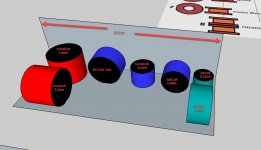
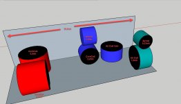
In any case, for those not familiar, the Testarossa is a small tower using the RAAL and two Satoris rather than one. Still a two way. Besides just getting my rocks off building another speaker (and learning), I have two primary reasons for wanting to do this. First is the increase in sensitivity, since I have a 25w amp, and the second is the benefits of two vs one MW, which I think will increase SPL in my smallish room, while liberating the tweeter a bit due to lower resistance values. I think it will sound better, and more full, and take some of the strain off my amp and improve dynamics a bit.

The first question I have centers around which version of the Testarossa I build, the options being a 10" passive radiator (which would be located on the side of the cab), or a ported version, which in my case would be located in the front to lessen boundary issues in my room. It seems the passive version would result in a different response from the MWs, since there is no air exchange, maybe tightening up the response a bit? I'm actually leaning towards the ported version, mostly to save a little $$ but also because I have a decent sub and always will so unless the PR has an obvious advantage I am wondering why I would use it. Jeff did in his own pair, and that counts for a lot in my book, but I don't have the experience to choose like some here.

There are also some details about the cabinets I pan to build that aren't according to the plans, and this is where the experimantation comes in, but maybe that's for another day, but I'll just say it involves mass, which I'm convinced can make a big difference. I come from a world of woodworking and carpentry machines and I've always noticed how much mass just "quiets" things down, and I think a cabinet that's vibrating is causing noise. When you push a piece of stock through a tablesaw, shaper, or planer that weighs a lot there's a smoothness that just can't be had with lighter machines!

Anyway, if anyone has any thoughts it would be helpful, thank you.

  • Locked
Soldering fumes

Has anybody gave a thought about soldering fumes ? I remember my father said that these fumes are comparable to a "fumes that originate from welding". Welding fumes are super dangerous actually. Companys with a little success are replacing humans with AI welding robots.

Soldering and welding, both are pretty much robotized. It is that dangerous. You can even exhaust it... it does not help... environment backfires everything... EMI effect 😀

Soldering > be it lead free or whatever solder, as soon as metal melts its over, heavy metal molecules will learn to fly, then they will overflow ur system and most important, a brain and after a good years of soldering its gg to ur input and output systems, including brain capability, sound, acoustical perception, everything.

Life will turn from REDish-Green-Bluish color to dark-matrix styled lightly colored lifestyle. It will take time, but everybody will experience it no matter where you live.

So, maybe we should somehow re-think our amplifier assembly and do it environment friendly ?

Why we have SMD at all lol... some say its cost saving and saves space.. i would say that with SMD technology we can use AI to produce more, faster and better cash...

I think i am off the voodoo **** now too...

From my experience as a cigarette smoker, then solder fumes are like 44x more dangerous to ur health system. Does not matter, if u inhale it directly or trought some filters or exhaust it entirely from the room.

And, TIN does make ur head "silently" dizzy, influencing the acoustical perception also.


.

Transformer trouble

Hi guys.
Stupid thing... I have a wallward transformer (the old kind, no switching PSU) for an inexpensive 1-in-4-out headphone amp that used to have 12VDC output. After I opened it on order to resolder the cable, it suddenly puts out 18VDC. This thing only has 4 diodes and an electrolytic cap! I testet the diodes and all are OK, switched the cap just in case. Any idea whats wrong with it?

MOSFET follower mounting in tube amps

Hi all,

When using a source follower to drive an output tube, e.g. tubelab's powerdrive topology, is it ok to mount the MOSFET to the chassis for cooling (insulated of course)? I ask because in Morgan Jones' book he cautions against mounting CCS devices on the chassis due to the loading caused by the capacitive coupling to ground. Interested to know if the same thing applies in follower applications, or isn't an issue due to the bootstrapping effect of the output voltage.

Appreciate your thoughts,

Greg

Pros and cons of different midbass horns

I'm looking for a midbass horn that can operate in the area of approximately 80-600 Hz. I use a Klipsch K-402 top horn, crossed at 500 Hz at the moment. I would like to match its directivity (90 h x 60 v). I have several JBL 2226 in bass reflex' for the lowest frequencies and use active cross over.

I need some basic information on the cons and pros of different horn profiles for this usage and what people would recommend.

Corner horn is not an option by the way. Free standing only. Having a horn that's a little bigger then K-402 is fine.

Ancient Hifonics tribute thread

I changed the thread title.


Anybody ever seen a series V Zeus with a board like this? Pwm. IRFP260M ps fets. Tip142/147 outputs.

I was expecting a ps with BJTs…

This one has a blown channel, mismatched outputs, and mismatched emitter resistors. Should be a straight forward Repair.

Attachments

  • image.jpg
    image.jpg
    801.8 KB · Views: 116
  • image.jpg
    image.jpg
    658.2 KB · Views: 118
  • image.jpg
    image.jpg
    657.2 KB · Views: 123
  • image.jpg
    image.jpg
    386.6 KB · Views: 119

Current gain opamp configuration headamp - a transimpedanceless DAC?

Hello,

Recently i was thinking about current drive, high output impedance and tewbs. In the interest of not derailing the question of the thread with why current driving sucks and we want damping and everything was designed with voltage drive in mind and so on, lets just take it as a premise that's what we want to do, hypothetically.

Normally we take the current out of a dac, turn it into a voltage (transimpedance), then amplify it, and so on, to the load it goes.
There are amplifiers that take the line out voltage and output a current, so the current is constant and the voltage varies (transconductance amp).
But what about taking out the middleman, never doing I/V, and using the current straight out of the DAC and just adding some gain with an opamp or whatelse to drive some headphones for example?
I mention opamps just because that's what i tried to build in LTspice, however i couldn't find a configuration that does what i want. In fact havent even really found any circuit for this out there, leading me to believe im embarking on something silly, or that of course the opamp might not be the thing i need for this, despite its many conveniences. In the attachment find the best i managed but it a bit fishy and not sure how to null it without a servo or something, since cant put a DC blocking cap in the loop.


Since this is DIY, i hope you can humour this concept, so in this thread i ask the basic 2 questions:
1. If we want to current drive something (say some headphones), why not start at the source and just add some gain to the current of the DAC, instead of doing I/V and then V/I?
2. If this can be done, how?

Regards,

Attachments

Hifonics Zeus VIII

This amp may actually be a Series VII in a VIII chassis not sure. Says ZEUS -1 on the board, and revision AA. Board is missing ALL TIP102 drivers in the PS/Vari circuitry. This board has no added components nor modifications what-so-ever.

Amp will work but from what I can tell the PS pulses on/off every ~1/4 second. I cannot probe pin #3 of the TL494 very well; especially unwell with a source plugged into RCAs. That source has common ground and good connections case-to-shields.

TL494
1. 3.384
2. 3.356
3. 4.61 <-- Had to measuring with Fluke 16 set to max/peak hold as it fluctuates every 1/4 second
4. 0.308
5. 1.479
6. 3.548
7. 0 <-- Black probe connected directly here
8. 14.19
9. 0.2 (Strobes)
10. 0.2 (Strobes)
11. 14.19
12. 13.62
13. 5
14. 5
15. 10.89
16. 6.75

Now, if I plug in something into the RCAs with good common ground the amp stabilizes slightly. As I increase input signal the amp becomes more stable.

Fear the PS FETs getting hammered on/off like this would cause failures.

Resistance between B- and RCA shields is 670ohm. Secondary ground is connected to RCA shields.

If I lower input voltage to about 10vDC, the amp locks into full duty cycle and stabilizes.


Any thoughts why this amp is cycling every 1/4 second at 14.4vDC?

3-driver loudspeaker sub to powerful? No compatible amp

Hey,
I want to build a 3-driver stereo bluetooth speaker with the following components:

2x https://www.soundimports.eu/en/dayton-audio-ps95-8.html
1x https://www.soundimports.eu/en/dayton-audio-e150he-44.html

Is the sub to powerful for the 2 speaker?
Which amp could i use? I only found some that are eather to powerful for the fulrange-driver or to weak for the sub.
What are potential problems I could run into?

Thanks in advance

Denon platter, help and reassurance required

I would like to say good afternoon but i may have a problem.

I've been working in my brothers shed while he is away. Today i realised i put one of those car subwoofers with a huge magnet next to his Denon platter which is one of the type with the magnetic tape on the rim for speed control. Would this magnet have affected the speed control thing? Its his pride and joy and I cant test it because the deck is locked in the house.

Hoping for a positive outcome, sp

Rockford 200 DSM

Got an untested Rockford 200DSM with leaking caps on the preamp riser board. Checked the amp for the usual blown mosfets (none), then thoroughly cleaned & recapped the entire amp 100% except for the large power supply caps. Still wasn't getting audio through the preamp board so I replaced the LM833 chips and now have clean audio. I made the rookie mistake of running the amp outside the heatsink for a few minutes on music and ended up blowing a couple outputs on the right channel. Replaced all 6 IRF540 and that channel works fine. I thought the left channel was good, but looking at the outputs with a 50hz tone I'm seeing the following from the two channels, and I'm not sure where to look:

Right channel:
SDS00037.jpg


Left channel (at different input voltages):
SDS00039.jpg

SDS00038.jpg

SDS00036.jpg

TU 8200 lost left channel

My TU 8200 DX performed flawlessly for 4 years from the first time I turned it on. I use it daily in my office.

The left channel died due to a tube failure. Now I can't seem to get bias voltage at pin 8 or 1 of the tube. It is correct at the base of the transistor then acts like a short to ground. Each component tests correctly. The tube also only heats up to about 50% of the channel that works but the heater voltage is correct.

Any ideas? It seems like a fairly simple circuit but it has me stumped.

  • Poll Poll
soundigital 12000.1 EVO

Soundigital 12000.1EVO

  • Soundigital 12000.1EVO

    Votes: 0 0.0%
  • C2 mosfet code

    Votes: 0 0.0%

Hi everyone ! I have this soundigital amplifier to repair and at first glance it has damaged final mosfets! The abbreviation of mosfets is C2, what kind of mosfet are they?

Attachments

  • 20220215_113610.jpg
    20220215_113610.jpg
    490.5 KB · Views: 261
  • 20220215_113619.jpg
    20220215_113619.jpg
    658 KB · Views: 410
  • 20220215_112550.jpg
    20220215_112550.jpg
    501.5 KB · Views: 285

Coil placement - 3 way crossover

Hi,

I have just finished designing my crossover for a three way speaker. Now I want to put the crossover in small box which is availble in the upper side of the midrange enclousre.
It´s dimensions are 30,5cm x 12,2cm x 9cm. There the complete crossover should be placed.
I have 7 coils in my crossover design. Two core coils for bass (red), one core coil and two air coils for midrange (blue) and two air coils for tweeter (green).
I have already read the article about placing coils from troels side:
http://www.troelsgravesen.dk/coils.htm

I am now struggeling placing all the coils in the small box without interacting each other (induction and crossover talk wise).
I have greated two suggestions (see attached pictures). Which one you would use?
Can you give me some suggestions what is the best placement?

Attachments

  • Coils_Version1.jpg
    Coils_Version1.jpg
    108.5 KB · Views: 391
  • Coils_Versipon2.jpg
    Coils_Versipon2.jpg
    101.6 KB · Views: 157

Am I subjective?

The new DIYAudio forum face looks good, by any technical standards, and with a few improvements could be close to perfect.

Then why am I subjectively no longer tempted to open the forum and post? It is not the quality of the current existing content, this followed a down path for years now, it's not the bore of endlessly teaching the basics like the Ohm law, it's not the endlessly seeing the same dusty implementations of 50 years old concepts and circuit topologies, it's not reading again and again the same stupid/wrong advice and being tired of rebuking and streamlining the topics.

It's simply no longer having fun to get involved in what I subjectively perceive as an impersonal and unfriendly virtual environment. Or I am getting too old for this ****. Or I need a new hobby.

One to another, I subjectively find the new forum format annoying, which is a nice way to say I hate it. BTW, I am turned off by the ASR forum as well (same software, I infer).

NAD C370 help pls

Hey guys, I recently finished recapping a C370. All the caps on all boards have been replaced. No other components have been touched. All swaps were checked for correct values twice. All solder joints were measured for continuity with other joints on the same trace and also checked to ensure there is no continuity to neighboring traces.

I'm trying to get the unit fired up for the first time since the refresh and the following happens (dim bulb tester used):

- DBT switch is off
- Amplifier power button is in the "on" position
- DBT switch to "on"
- Amp power light turns on, DBT no light
~1.5 secs later
- Amp power light still on, something clicks in amp (sounds like relay), dbt flashes on and immediately shuts off along with another click from amp

The last event repeats about once every second.

I don't dare leave the DBT on for more than two cycles of this since I don't know what's going on.

Is this a result of all the caps being fresh and drawing too much current and setting off a protection circuit? If so, what's the solution - just let it click on and off until it settles down?

Or has something gone terribly wrong?

Inductors on Kicker 06zx750.1 amp

I need to rewrap the inductors on my Kicker 06zx750.1 class d monoblock car amp as the shielding on 1 has failed, 2nd doesn’t look too bad to where it would malfunction so I tested it on my cheap-o LCR tester and got a reading of .12mH and .32-.36ohms. Does that seem anywhere near right for this amps inductors?

As far as the inductor itself it seems to be a brown(green on 1side) core that measures 40x23x15mm with what seems to be 10awg magnet wire (waiting for wire gauge feeler) it has 35 turns total, 20 1st wrap, 15 on 2nd wrap.

I guess I could just rewrap each core with appropriate length/size/turns of magnet wire and just be done with it, but would like to know what the inductors for this amp are supposed to test as so I can make sure it’s correct. Thx

Attachments

  • 13E3FAB0-BF5A-474E-8768-80FCD7862489.jpeg
    13E3FAB0-BF5A-474E-8768-80FCD7862489.jpeg
    339.3 KB · Views: 117
  • 3F547780-86B3-4C02-BF87-449E1C496617.jpeg
    3F547780-86B3-4C02-BF87-449E1C496617.jpeg
    470.5 KB · Views: 98
  • 072CA616-80AA-4C21-8E48-8E479743D5C7.jpeg
    072CA616-80AA-4C21-8E48-8E479743D5C7.jpeg
    371.6 KB · Views: 122

Rockville RXA-T1 board replacement.

Hello all,
The amp in my son's car stopped working a while back. We checked the fuses and confirmed that it is getting power. He was going to replace it but we found that you could order a replacement board from Rockville, so that's what we did. We have the amp opened up and the old board removed but before we just slap in the new board I have a question. On each of the long sides of the board there are some tabs that were held down with metal straps to the amp housing. The tabs themselves were not screwed down but they did have a white paste under them. I don't know what these tabs are or what the white paste is but I would like to clean it up and put fresh "paste" down first. It's this some type of heat sync paste or dielectric grease? Any help would be appreciated. I imaging Rockville isn't the only company with this type of design.
Thanks in advance!
Matt

Attachments

  • 16446216101865076365209508380626.jpg
    16446216101865076365209508380626.jpg
    229 KB · Views: 118
  • 16446216571287771732446841054782.jpg
    16446216571287771732446841054782.jpg
    360.3 KB · Views: 122
Projects by fanatics, for fanatics
Get answers and advice for everyone wanting to learn the art of audio.
Join the Community
507,756
Members
7,886,873
Messages

Filter

Forum Statistics

Threads
406,164
Messages
7,886,873
Members
507,756
Latest member
CalmRiver