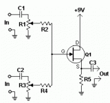
Hello all. I wanted to fool around with a jfet tone control. I am just only starting out with these types of circuits so would like to request some help please. Are either of these two circuits suitable for inserting into a two-way passive tone control. That's all I am after, really. Just a simple jfet based bass and treble control
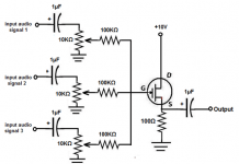
Also, is it possible to build a mixer stage using either circuit to mix three of those "toned" mono channels together and then send to a quality pc type 2.1 active speakers? That would be a bonus
It appears that all parts that I will require for this design are available in my local Jaycar electronics shop. They don't have any other audio jfets
Please recommend a two-way tone schematic that I can use with one of the two circuit images. This is for my daughter and friend to practice bass, guitar and singing. I am a bit short of time as today is Wednesday, and they start their lessons on Friday. I have something they can use if I don't get this ready on time. I want to make something like this though as I feel that a minimum of controls would be awesome for these year 4 girls and their teacher to find a basic sound
Thanks and regards
Randy

See page 3. These parts are obsolete, but you can substitute more modern devices if you have some electronics knowledge.
https://www.ti.com/lit/an/snoa620/snoa620.pdfI don't recommend the LM1036, it is prone to oscillation on its output unless suppression components are added.
Googling "JFET tone control circuit" seemed to bring up lots of possibilities.
https://www.ti.com/lit/an/snoa620/snoa620.pdfI don't recommend the LM1036, it is prone to oscillation on its output unless suppression components are added.
Googling "JFET tone control circuit" seemed to bring up lots of possibilities.
I found this web site about guitar amplifier tone stack circuits.
https://monster.partyhat.co/article/amplifier-tone-stacks/
The problem with a passive tone control circuit is that it requires extra gain to compensate and therefore noise.
The problem with JFETs is the unpredictability of Idss, which makes a circuit without a source resistor, like the second one you posted, a crap shoot unless you carefully select parts with, in this case Idss= (18V/2)/2.7k ~= 3 to 4 mA. With the Idss = 2 to 20 mA spec, the odds of getting suitable parts are about 5.5%. The source resistor in the first circuit reduces the range of behaviors of the circuit with different parts, but a bit more complicated circuit could make the circuit fairly predictable. You could change R1 to compensate for whatever Idss you get, but at 20mA, your preamp is going to waste a lot of heat/battery and you have to hand select parts; probably have to buy a lot of spares. For a hobby, this is fine, but you can see why JFETs are not a popular strategy for larger manufacturers and therefore why semiconductor manufacturers are abandoning signal JFETs.
Hello all. Thank you
I have a USB/battery powered little bluetooth mixer that does a fine job with bass/mid/treble as well as echo on the instrument channel. It has an aux in too. That sits well with the 2.1 pc speakers
I just wanted to experiment with the locally available MPF102 jfet to experience the jfet sound and simplify the setup
Yesterday, I picked up all the parts to make three sets of the second image. I will grab some 1meg, 270ohm and 22n today too so that I can play with either circuit. I would appreciate any recommendations to improve either circuit
Thank you. Where would I find the values for image one? Image two states 10v for power. Would that work with 9v? Can the MPF102 be used in this circuit?
Thanks for all the help, guys. I am banging my head against the wall trying to work out the pinout on the pc speakers DB15 connector. It's a Logitech Z623 sub that I found second hand for $10, it was missing the satellites that have the controls incorporated in the left speaker. I have one already and tried swapping the speakers and the new one works fine
The Z623 features three pairs of stereo inputs that are not switched, but instead mixed internally. I am hoping to exploit this. I am right now building an enclosure that will take the sub box as well as a pair of full ranges to make a stereo capable amp/cab combo with live mono input channels as well as a stereo input. I'll add wheels and a retractable handle with a music book stand built into the handle
I found the standby switch and sub in on the pinout already from internet searches. I know the right speaker connector. I know the RCA stereo channel one input connector
The brains for input mixing and sub filter are either in the sub box pcb or left speaker pcb and the DB15 contains pins for left speaker out which I think I can see coming from the poweramp section so I think I am good with that one too
I need to find the left and right inputs on the DB15 connector. If the main volume is a dual gang pot on the left speaker then I am guessing that the main/sub filter is on its PCB and since the DB15 has a sub direct input then I am again guessing that the control PCB splits the stereo input to left, right and sub and sends them to discrete inputs pins on the DB15
This would mean that since I do not have a control PCB for the new Z623 then I basically have a three channel poweramp and 2.1 drivers with the left and right pair consisting of LG branded full ranges rated 40w and 4 ohms that I have lying around
This would now mean that I would require preamp/eq for each instrument channel, as well as a mixer stage and a main/sub filter
I also picked up three black box universal type preamps as well, just in case the jfets didn't work out and the Bluetooth mixer played up with noise and things
I'll post some pics soon of where I am at. One thing I am aiming for overall is for the combination to be able to play sub contra to sub sub contra with authority, so I am calling it the Low-b623 project for personal amusement and will share back all my findings as well as implementation so anyone else interested can fool around with this too. there are lots of expansion possible for eg. fitting switch 6.5mm sockets in the enclosure in the path of the main speakers so I can plug in larger external speakers and disable the built in drivers on need for a wider stage and louder volume. I should be able to fit a dedicated Bluetooth reciever into the enclosure and also things like dedicated channel effects loops and USB interface
Thanks and regards
Randy
I have a USB/battery powered little bluetooth mixer that does a fine job with bass/mid/treble as well as echo on the instrument channel. It has an aux in too. That sits well with the 2.1 pc speakers
I just wanted to experiment with the locally available MPF102 jfet to experience the jfet sound and simplify the setup
I found this web site about guitar amplifier tone stack circuits.
https://monster.partyhat.co/article/amplifier-tone-stacks/
The problem with a passive tone control circuit is that it requires extra gain to compensate and therefore noise.
The problem with JFETs is the unpredictability of Idss, which makes a circuit without a source resistor, like the second one you posted, a crap shoot unless you carefully select parts with, in this case Idss= (18V/2)/2.7k ~= 3 to 4 mA. With the Idss = 2 to 20 mA spec, the odds of getting suitable parts are about 5.5%. The source resistor in the first circuit reduces the range of behaviors of the circuit with different parts, but a bit more complicated circuit could make the circuit fairly predictable. You could change R1 to compensate for whatever Idss you get, but at 20mA, your preamp is going to waste a lot of heat/battery and you have to hand select parts; probably have to buy a lot of spares. For a hobby, this is fine, but you can see why JFETs are not a popular strategy for larger manufacturers and therefore why semiconductor manufacturers are abandoning signal JFETs.
Yesterday, I picked up all the parts to make three sets of the second image. I will grab some 1meg, 270ohm and 22n today too so that I can play with either circuit. I would appreciate any recommendations to improve either circuit
Some jfet mixers
Thank you. Where would I find the values for image one? Image two states 10v for power. Would that work with 9v? Can the MPF102 be used in this circuit?
Thanks for all the help, guys. I am banging my head against the wall trying to work out the pinout on the pc speakers DB15 connector. It's a Logitech Z623 sub that I found second hand for $10, it was missing the satellites that have the controls incorporated in the left speaker. I have one already and tried swapping the speakers and the new one works fine
The Z623 features three pairs of stereo inputs that are not switched, but instead mixed internally. I am hoping to exploit this. I am right now building an enclosure that will take the sub box as well as a pair of full ranges to make a stereo capable amp/cab combo with live mono input channels as well as a stereo input. I'll add wheels and a retractable handle with a music book stand built into the handle
I found the standby switch and sub in on the pinout already from internet searches. I know the right speaker connector. I know the RCA stereo channel one input connector
The brains for input mixing and sub filter are either in the sub box pcb or left speaker pcb and the DB15 contains pins for left speaker out which I think I can see coming from the poweramp section so I think I am good with that one too
I need to find the left and right inputs on the DB15 connector. If the main volume is a dual gang pot on the left speaker then I am guessing that the main/sub filter is on its PCB and since the DB15 has a sub direct input then I am again guessing that the control PCB splits the stereo input to left, right and sub and sends them to discrete inputs pins on the DB15
This would mean that since I do not have a control PCB for the new Z623 then I basically have a three channel poweramp and 2.1 drivers with the left and right pair consisting of LG branded full ranges rated 40w and 4 ohms that I have lying around
This would now mean that I would require preamp/eq for each instrument channel, as well as a mixer stage and a main/sub filter
I also picked up three black box universal type preamps as well, just in case the jfets didn't work out and the Bluetooth mixer played up with noise and things
I'll post some pics soon of where I am at. One thing I am aiming for overall is for the combination to be able to play sub contra to sub sub contra with authority, so I am calling it the Low-b623 project for personal amusement and will share back all my findings as well as implementation so anyone else interested can fool around with this too. there are lots of expansion possible for eg. fitting switch 6.5mm sockets in the enclosure in the path of the main speakers so I can plug in larger external speakers and disable the built in drivers on need for a wider stage and louder volume. I should be able to fit a dedicated Bluetooth reciever into the enclosure and also things like dedicated channel effects loops and USB interface
Thanks and regards
Randy
MPF102 were what stayed in the pot when all other FETs with
interesting data had been selected out. Hard to find worse.
interesting data had been selected out. Hard to find worse.
I am going to pick up the additional components to make either circuit as well as this one
https://www.electroschematics.com/fet-audio-mixer/
Hope I end up with something that sounds musical
https://www.electroschematics.com/fet-audio-mixer/
Hope I end up with something that sounds musical
Probably why they are popular for guitar effects!MPF102 were what stayed in the pot when all other FETs with
interesting data had been selected out. Hard to find worse.
I think I have those in analogue muting circuits in some of my synths.Probably why they are popular for guitar effects!
- Home
- Source & Line
- Analog Line Level
- MPF102