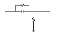
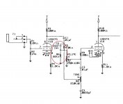
I'm trying to understand how the tone stack of my Fender Pro Jnr amp works and I'd like some help in understanding this part of the circuit. It's placed between the C1 coupling cap and the volume/tone controls. It seems to be a L-pad attenuator with a parallel cap added, so does it attenuate the signal above or below a certain frequency maybe? I've searched alot but can't seem to find this exact circuit. Thank you.


It shelves the lower frequencies down. Also sometimes called a peaking circuit, although it doesn't really peak.
Rather it attenuates the lows and passes the highs unattenuated.
The amount of low frequency loss depends on the relative values of the resistors.
Rather it attenuates the lows and passes the highs unattenuated.
The amount of low frequency loss depends on the relative values of the resistors.
Last edited:
It IS a roughly 10:1 attenuator, obviously they are dropping gain to make sound cleaner.
C22 is a treble boost, problem is it´s too small, boost starts at 16kHz, way too high to be of any use at Guitar frequencies.
C22 is a treble boost, problem is it´s too small, boost starts at 16kHz, way too high to be of any use at Guitar frequencies.
Do you mean C2 is a treble boost JMFahey? I'm surprised they would want to boost the treble on this amp as it is known for its seering, ice-pick highs. Would a smaller value for C2 make that treble boost even less effective, if one wanted to reduce treble? Also rayma, if one wanted to increase bass would you increase the resistor values or decrease?
Try just leaving out the capacitor C2 altogether, since it's a really small value already.
I think the original purpose of C2 was to compensate for the high frequency roll off in the following stage.
Without the C2, this is just an attenuator, probably serving to increase the input stage distortion.
If you need more bass, try increasing C1 to 0.22uF.
I think the original purpose of C2 was to compensate for the high frequency roll off in the following stage.
Without the C2, this is just an attenuator, probably serving to increase the input stage distortion.
If you need more bass, try increasing C1 to 0.22uF.
Last edited:
Thanks rayma. Yes I was planning to change C1 to 0.047uF but you think 0.1uF can be used safely too? Just trying to understand the 'peaking circuit' I notice that the 5F2A Princeton has an identical tone stack design to the Pro Jnr (with different values) but doesn't use the peaking circuit. If I was to leave the circuit out altogether what would the effect be - less gain and a cleaner signal?
If the input can be less (so the volume knob is about the same without the circuit),
the output will be cleaner, but it will have somewhat more hum and hiss.
First I'd remove the C2. If that is favorable, then change C1 to 0.1uF or 0.22uF polypropylene.
If that is favorable, next try removing (open circuit) the R6, which will increase the gain (and noise).
If that is good, then try shorting the R5, which will increase the gain (and noise) even more.
Last edited:
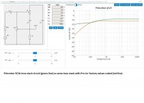
OK thanks I'll give that a try. Just out of interest, I plugged the Pro Jnr values into the 5F2A tone stack simulation over at guitarscience.net. The first plot is the stock PJ values (minus the extra peaking circuit) = Red vs the 5F2A std tone stack = Green. The PJ shows less treble and less bass than the 5F2A. Maybe the peaking circuit was intended to provide some boost to the lower treble level here. I don't know what "RL" is so I just left that at the default 1M. The second plot shows the effect of 0.01uF, 0.047uF and 0.1uF coupling caps at C1 on the Pro Jnr tone stack. The larger C1 caps don't look too bad except for a slight upper bass hump. Not sure how it would look once you included the extra peaking circuit though. (which isn't part of the 5F2A simulation).
.

.


It works so high, that it has NO audible effect.Do you mean C2 is a treble boost JMFahey? I'm surprised they would want to boost the treble on this amp as it is known for its seering, ice-pick highs. Would a smaller value for C2 make that treble boost even less effective, if one wanted to reduce treble?
Removing it will not change anything, so flip a coin 🙂
Maybe there was some other reason for it (stability?) but not equalization.
If you increase it, say to 220pF, then you would get "nails on the blackboard" highs ... I guess you don´t want that. 🙂
In any case, Pro Jr is a nice little amp, and sounds very good if used as tube amps are meant to: loud 😱
Pedal platform? ... not so sure.
True, but would be nice to have it a bit more 'flexible' rather than just a one trick pony. I also plan to fit a Framus mid control for those more mellow moments. 😢
I've just been comparing the schematics for my 1994 PJ vs the 2005 Rev F schematic and Fender has reduced R6 from 56k to 22k in the newer model, so looks like they've decided to reduce the preamp's gain and give it more clean headroom.
L = Load So RL is the load impedance.OK thanks I'll give that a try. Just out of interest, I plugged the Pro Jnr values into the 5F2A tone stack simulation over at guitarscience.net. The first plot is the stock PJ values (minus the extra peaking circuit) = Red vs the 5F2A std tone stack = Green. The PJ shows less treble and less bass than the 5F2A. Maybe the peaking circuit was intended to provide some boost to the lower treble level here. I don't know what "RL" is so I just left that at the default 1M. The second plot shows the effect of 0.01uF, 0.047uF and 0.1uF coupling caps at C1 on the Pro Jnr tone stack. The larger C1 caps don't look too bad except for a slight upper bass hump. Not sure how it would look once you included the extra peaking circuit though. (which isn't part of the 5F2A simulation).
.View attachment 1024640View attachment 1024641
- Home
- Live Sound
- Instruments and Amps
- What's the function of this circuit?