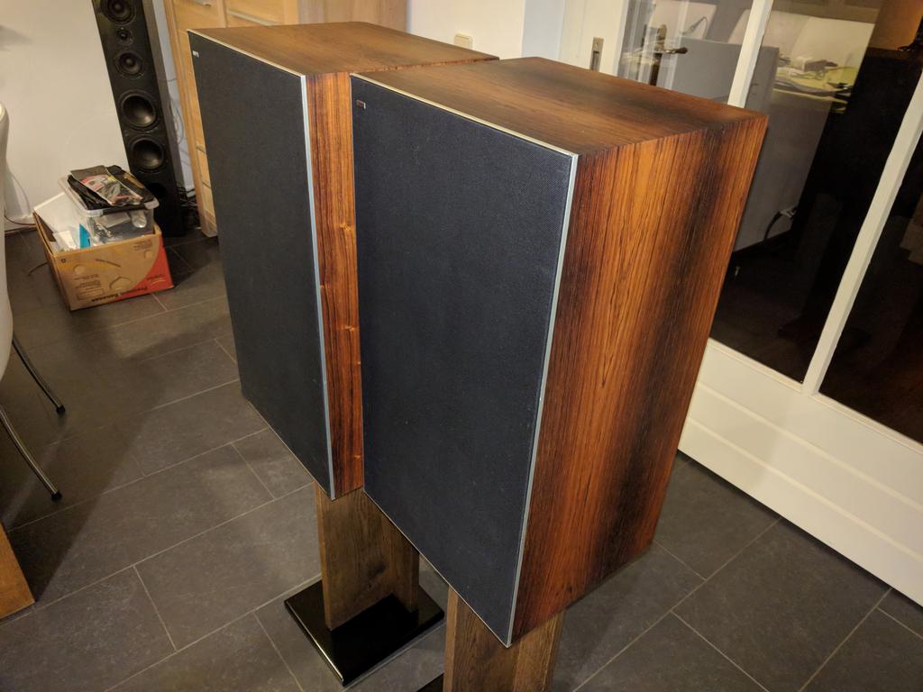
Bang & Olufsen Beovox 5700, classic vintage loudspeakers restoration, renewal, repair
I acquired these speakers a while back.
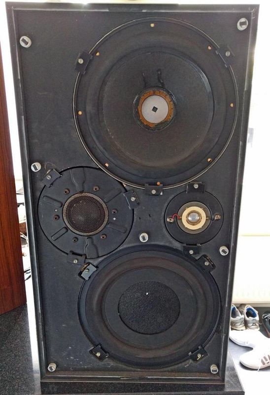
The speakers looked terrible, they were scratched and smeared with white muck / paint, dusty and very dirty and sticky. At the top were circles in the wood of lime/water that had leaked from flower pots or something. The foam dust caps in the woofers were completely perished. The pieces of foam fell out when I removed the front.
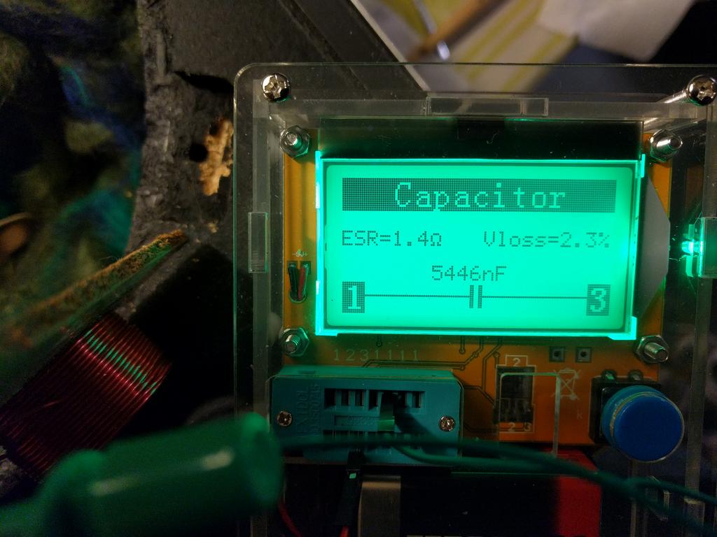
One of the resistors in the filter of a loudspeaker was completely burned out. Most electrolytic capacitors had wrong values and / or had an ESR of 1 to about 2 Ohm.
What have I done?
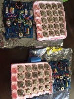
- Crossover filters largely renewed / upgraded, all wrong value electrolytics capacitators of 44 years old off and replaced by Jantzen audio MKP capacitors that virtually do not age, and have much better specs (especially much lower ESR).
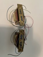
- The orientation of the coils adjusted to reduce crosstalk. To my surprise, Bang en Olufsen had not paid attention to this at the time of manufacturing.
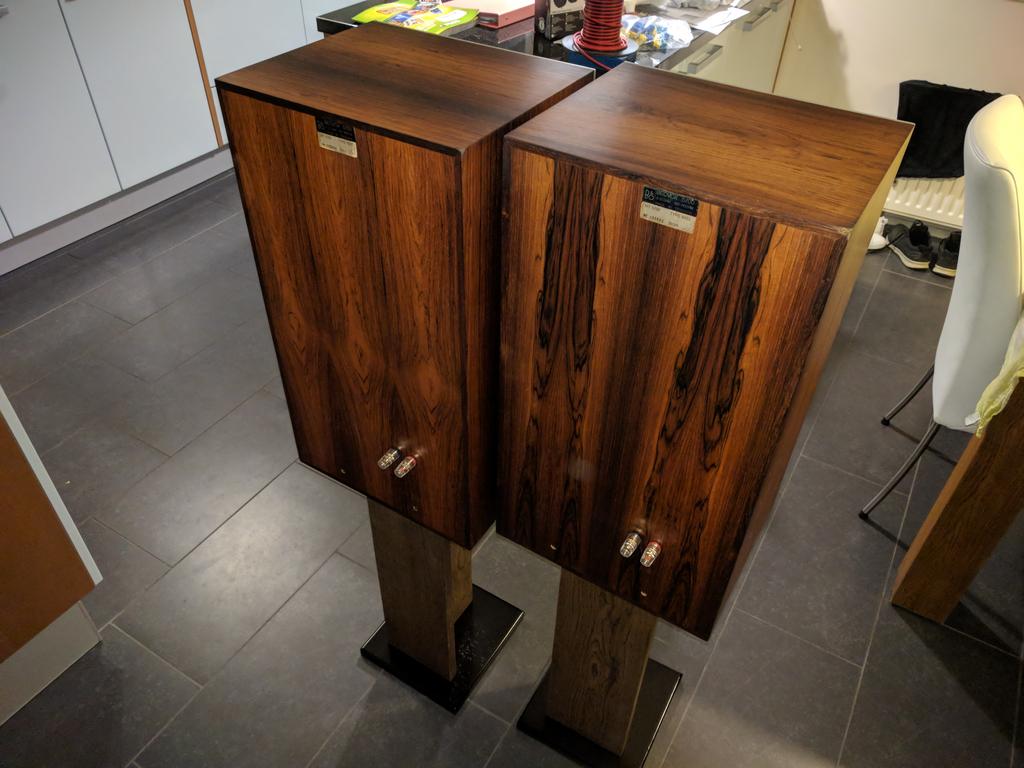
- The Rosewood veneer completely refurbished, all stains and the scratches and dirt removed, sanded and then oiled again. Sanded with grit 180 and grit 240, sanding only in the longitudinal direction of the wood grain! Treated the surface with hard wax oil from Rubio Monocoat.
- All units airtight fitted with new sealing tape.
- Mounted decent speaker terminals at the back, instead of the loose wires through a hole from the speaker.
They play excellent again, these are really fine speakers!
Any opinions or remarks?
These were the most expensive speakers of Bang & Olufsen at the time.
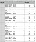
The specifications:
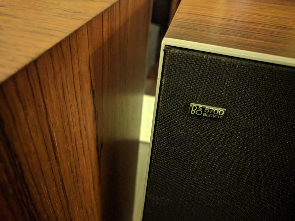
B & O, Bang and Olufsen, Beovox 5700, HT 5700, type 6253
100 Watt max. Power
impedance: 4 ohms
Frequency range: 35 - 20,000 Hz
max. harmonic distortion: <1%
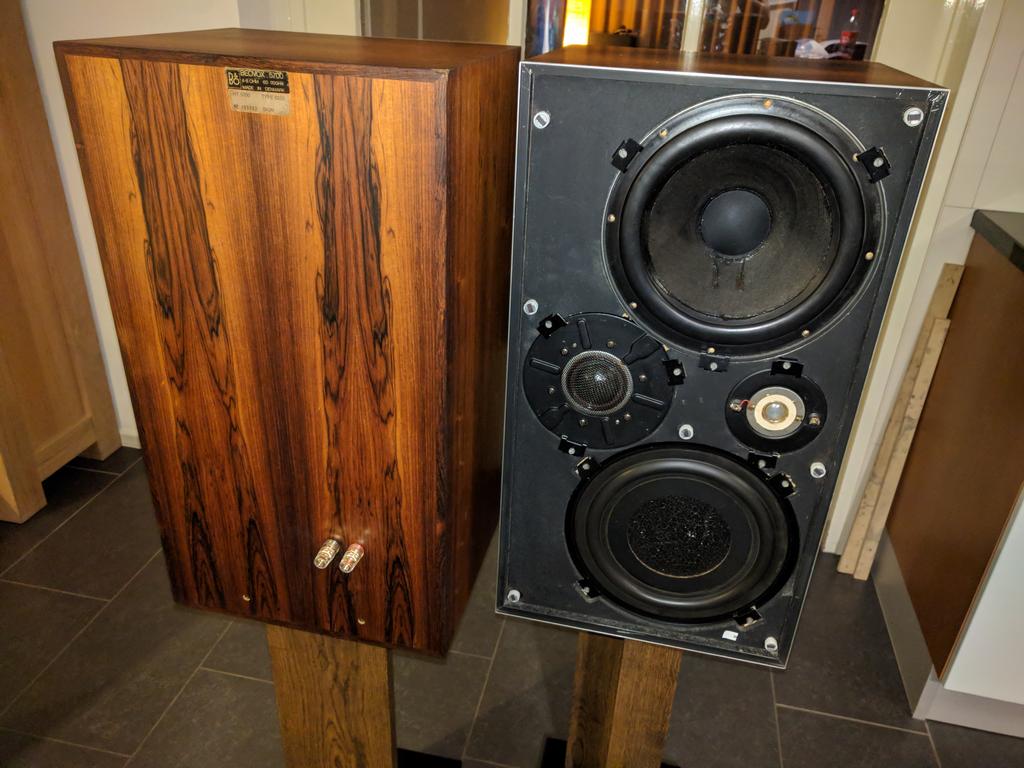
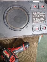
woofer: 22.5cm Philips AD 1056 / W8
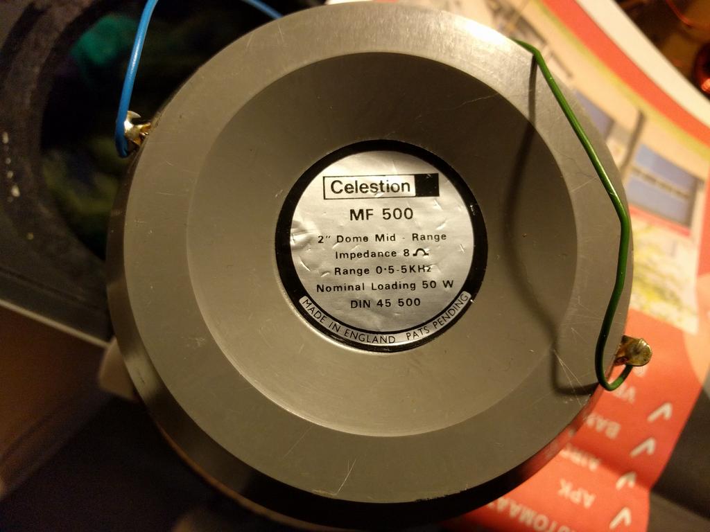
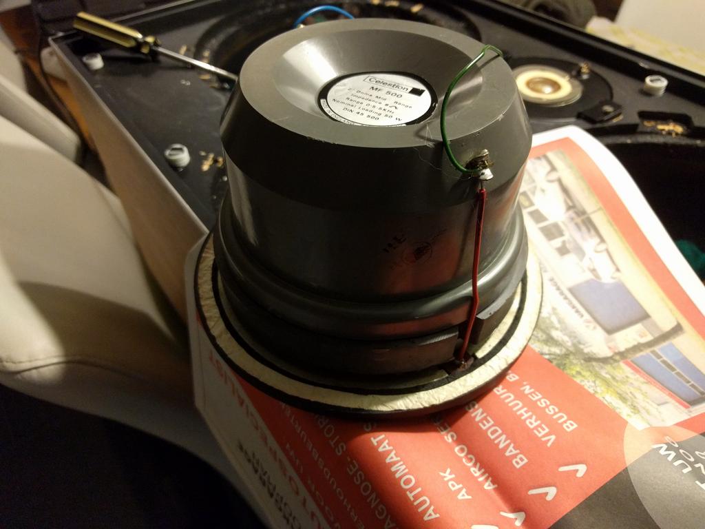
mid tone: Celestion MF 500
tweeter: Celestion HF 2000
passive radiator 25cm
crossover frequencies 600 - 6000 Hz
dimensions: 36 x 66 x 30 cm
weight: 22.5 kg
version in rosewood / rosewood veneer
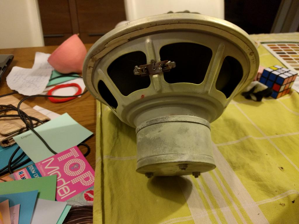
Philips alnico woofer AD 1056 / W8
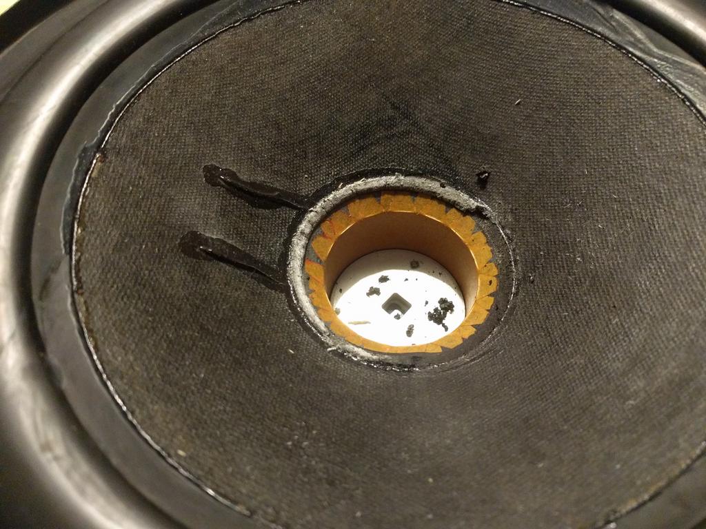
The philips AD 1056 / W8 woofer, the foam dust cover remnants for removal
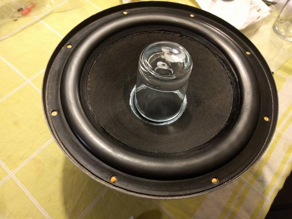
New linen dust cover glued in, temporarily fixed and weighted with a glass
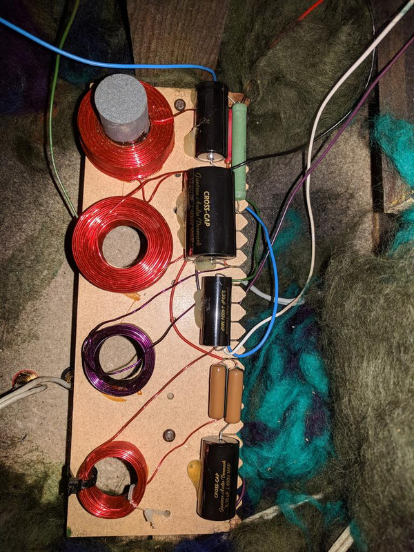
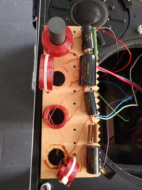
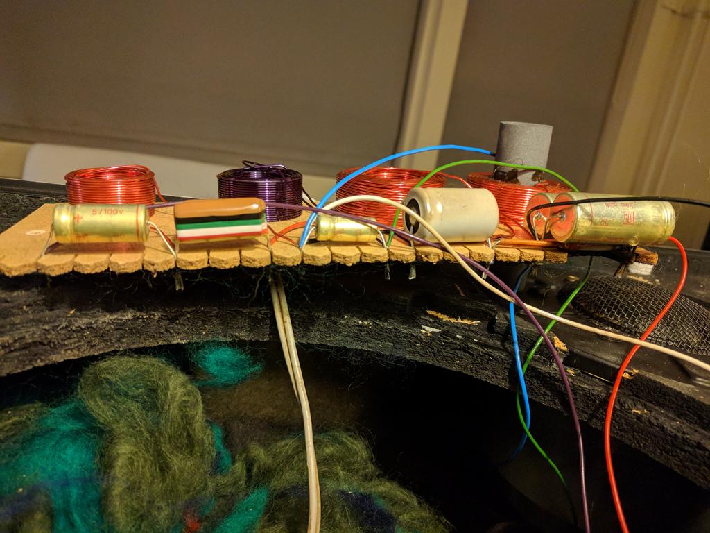
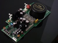
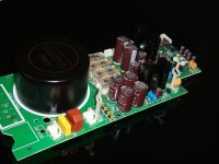
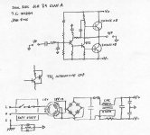
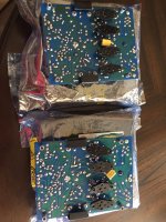
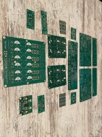
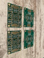
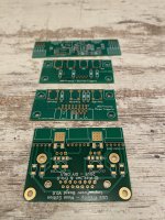
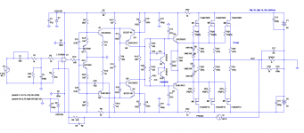
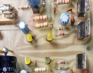
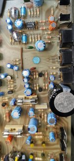
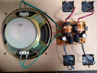
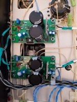
The crossover filter after upgrading with Jantzen Audio cross-cap MKP capacitors. The coils are rotated to minimize mutual crosstalk through the generated electromagnetic fields.
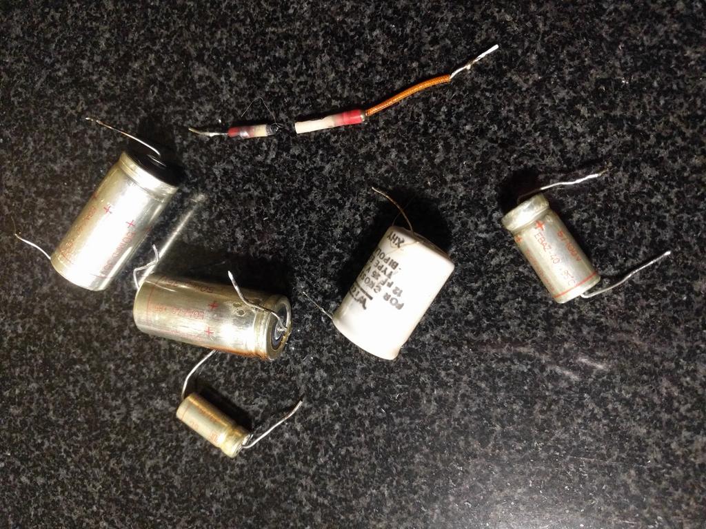
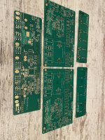
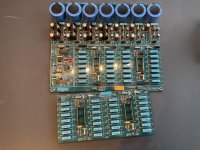
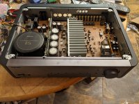
The old components, with the burnt-out / broken resistor of 22 ohms
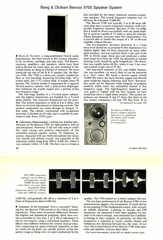
Above review of the speakers from the American magazine: stereo review, number 3 from 1972
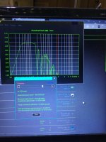
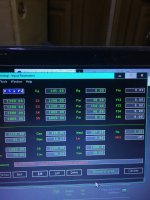

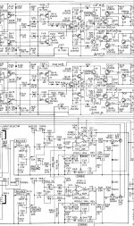
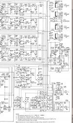


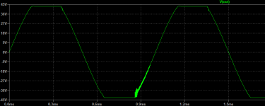
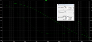
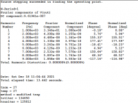
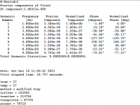


 - see MathCAD.