Wavelets....as per this article.. Signal Aligning Using Wavelets
Surprisingly repeatable measurements for low frequencies, that normally drive us crazy trying to nail down timing/phase at xover.
Works great with Arta...just like the article says")
Surprisingly repeatable measurements for low frequencies, that normally drive us crazy trying to nail down timing/phase at xover.
Works great with Arta...just like the article says
How do you use group delay to tell apart constant fixed delay, phase, and polarity?
It's a serious question.
I don't mess much with IIR xovers, so I'm always looking for easiest methods to use in the field, when a gun is put to my head and i have to use them.
I've seen advocates of matching group delay, but that seems tenuous compared to matching overlaying phase traces. That's just my gut feeling though, never delved into how far group delay matching might work.
The thing I think is really neat about the wavelets (in limited initial testing) is how repeatable, very tightly grouped, multiple timing takes are. Been measuring 40Hz wavelets acoustically with very consistent constant delay. Can't say I've ever seen that before from anything...
How do you use group delay to tell apart constant fixed delay, phase, and polarity?
It's a serious question.
Sorry to do a bit of thread hijacking, but to answer your question: you use interference, or an interferrogram if you prefer that term.
This involves taking three measurements, or at least N+1 measurements for N drivers, with the microphone always in the same exact position. The measurements are taken with un-filtered input. There is a measurement taken for each driver, with only that driver operating. Then one or more measurements with two or more drivers operating at the same time is taken. This is the "interference" data.
It turns out that the interference of two signal sources, when the group delay is not large, is very sensitive to the relative group delay between the two drivers. You will get some constructive and destructive interference taking place, and these peaks and dips are a "fingerprint" of not only the delay but also the polarity of the two sources. Because you have already taken individual measurements of each driver, those contain the driver's own phase response. Thus is it only a matter of some fitting or experimentation to obtain the polarity and group delay that is captured by the interference measurement.
You do this by adding the measurement of the individual drivers in software (e.g. in a crossover modeling program) with some guess at the polarity and delay. It is not difficult to manually adjust the relative delay between the two drivers so that the software-constructed sum matches up very closely to the measured sum (the two-driver measurement you performed). I have been able to differentiate group delay down to about 0.1 milliseconds, sometimes better, using this technique.
When your system has more than two drivers, you must take additional measurements and repeat this procedure. Often it is relatively easy to match the phase for low crossover points, so this technique is most applicable to midrange and tweeter drivers and their crossover.
TIP: The sensitivity of the technique is maximized when the gain is adjusted so that the level (e.g. measured SPL) from each driver is about the same, ie that is overlaps as much as possible and is not 6dB or more different.
I have done this kind of group delay (or z-offset as some call it) determination many times when doing only single channel measurements in ARTA. If you can do dual-channel measurements you can directly measure phase, and therefore delay and polarity, making this approach is a MOOT POINT.
How does this compare to the wavelet approach? Well that works for one frequency, or around that frequency, because the wavelet is localized in the frequency domain. The approach I described above is doing that for all frequencies (within the passband) simultaneously and so is probably more robust a method.
Last edited:
Thanks for all that Charlie, well written and quite clear. No hijack at all
I'm familiar with that method. I've thought of it as the null method for use with single channel work. And like you say dual channel, going straight to phase, makes it moot.
The biggest problem I've had going straight to phase with dual channel, or any technique that digs out phase such as single channel swept sine (ie REW)
is that anything FFT based has a hard time in repeatably locating low frequency timing with precision. Using the usual sine sweeps, PN whether random or periodic, MLS, etc.
You know, the very nature of FFT divided linearly across the spectrum, not much data down low.
The kicker about the wavelets, is just as Pat Brown says in his article (pls read !) is that wavelets are a compromise stimulus signal designed to give both the frequency domain and the time time what's needed in each of their domains, to let FFT do a better job.
So far, i pretty psyched about it.
Good stuff, eriksquires.
The thing about wavelets i'm hoping to get across, is that i think they may be a fundamentally better way to collect timing data at low frequencies.
Any of our measurement programs can easily give accurate timings, once above 3-5 octaves up from bottom, how low depending on their robustness.
At mid and high freqs, i think many ways can get time alignment close. They only vary in how fine an alignment can be achieved.
Definitely not so, down low. Not easy at all. And single channel methods like null, can easily be off by a period or multiples.
The cool thing about wavelets, is they seem to be all about trying to solve/mediate a FFT's inherent dilemma, time vs freg.
And as far as i know, every measurement program relies on FFT, no?
@ mark100: The wavelet approach is an interesting alternative for determining the relative group delay at lower frequencies. If using the method I described, it's difficult to get good wideband measurements below 500Hz, or at least measurements with sufficient frequency resolution. The wavelet approach might be able to get around this problem because it should be possible to eliminate contributions that arise from reflections, or anything other than the direct sound.
On the other hand, even if you only use a 5 cycle burst wavelet, at 100Hz this requires 50msec to complete. As a result, is is likely already contaminated with room wall/surface reflections that tend to appear in as little as 5msec after the direct sound in an indoor space.
I'm curious if you have tried doing a burst/wavelet measurement down around 100-300Hz? Does it work? Can you get clean enough data?
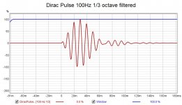
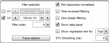
You can use REW to 1/3 oct filter the impulse of an existing measurement and get a wavelet response but only at set frequencies.
This is a Dirac Pulse with 100Hz 1/3 octave filtering which doesn't answer your question on room response but you could try it with your own measurements to see the effect.
This is a Dirac Pulse with 100Hz 1/3 octave filtering which doesn't answer your question on room response but you could try it with your own measurements to see the effect.
Attachments
@ mark100: The wavelet approach is an interesting alternative for determining the relative group delay at lower frequencies. If using the method I described, it's difficult to get good wideband measurements below 500Hz, or at least measurements with sufficient frequency resolution. The wavelet approach might be able to get around this problem because it should be possible to eliminate contributions that arise from reflections, or anything other than the direct sound.
On the other hand, even if you only use a 5 cycle burst wavelet, at 100Hz this requires 50msec to complete. As a result, is is likely already contaminated with room wall/surface reflections that tend to appear in as little as 5msec after the direct sound in an indoor space.
I'm curious if you have tried doing a burst/wavelet measurement down around 100-300Hz? Does it work? Can you get clean enough data?
Hi Charlie, first a disclaimer. This is only my second/third day playing with this technique, and much of that time has been learning Arta in general.
That said, i'm more convinced than ever these wavelets are a more precise distance locater for low frequencies than anything i've seen yet.
Crazy consistent time location even at 40Hz (lowest i've played with so far.)
We are talking down to samples location.
This has been 10+ ft out in room using Arta's 'Signal Generation and Recording' under Impulse Meas. Reflections galore.
I'm using 5 cycle bursts shaped. Triangle seems to work even better than Gauss. The burst shaping makes reflections within the widow time less interfering it seems.
Much to learn still....
You can use REW to 1/3 oct filter the impulse of an existing measurement and get a wavelet response but only at set frequencies.
This is a Dirac Pulse with 100Hz 1/3 octave filtering which doesn't answer your question on room response but you could try it with your own measurements to see the effect.
Yes, REW does a great job at displaying 1/3 fractional octave impulse filtering.
My take is REW mathematically extracts a "1/3 octave wavelet" from a full spectrum, or at least to the extent it can, a limited spectrum impulse response...just needs enough high freq spectrum to get its bearings.
Whereas the wavelet technique uses a single freq spectrum as the excitation signal, and simply records what is produced.
A scope works to measure it, no FFT interpretation needed.
Arta just makes it easy by providing both a digital storage scope, and a dual channel FFT, with its scope triggered off the wavelet stimulus.
It appears to me so far, there is a world of difference in the precise timing location of low-freq-only impulse peaks, using the wavelet technique vs REW, Smaart, etc, ... or any analyzer using noise, swept signals, MLS, etc...
Seems to be all about the stimulus signal...
Last edited:
I don't think this is the case but I do agree that using the wavelets created at specific frequencies is a very good stimulus for measuring these sort of things as the time frequency tradeoff has been baked into the signal and makes it much easier to get right.Seems to be all about the stimulus signal...
I'm curious if you have tried doing a burst/wavelet measurement down around 100-300Hz? Does it work? Can you get clean enough data?
Ran a bunch of time location experiments this morning, on a sub indoors with the mic about 6 ft away. Sub was low passed at 100Hz, with a LR 72dB/oct.
Idea was to compare REW, Smaart, and the wavelet technique using Arta, for how consistent they were at measuring delay times against loopback.
Made a dozen measurements with each....
The sub's low pass was via a FIR filter, where total processing latency was about 46ms, so with sub-to-mic time-of-flight , expected delay against loopback was around 52ms.
I started with Smaart, as it's my go-to and best known measurement program.
Dual channel using pink noise (tried both random and periodic).
Using Smaart's automatic Delay Finder, measurements had an average delay of 52.23ms, with 0.83ms variance from high to low.
Must say i was a little surprised by the amount of variance so i went to look at the Delay Finder's FFT settings, but it appears Smaart has removed the ability to adjust them in latest version. So it is what it was.....
Then on to REW. Used a sweep constrained to 20-500Hz, with a 256k size.
Against loopback, delay measurements averaged 52.12ms, with only 0.18ms variance. What a pleasant surprise !
Several years ago i did a similar shootout, REW vs Smaart vs Systune.
At that time REW had more trouble than either of the two dual channel programs. Don't know what changed but i sure like it. Or maybe i just made a mistake. Wish I had the REW version number from back then. Currently using 5.20.
Ok, Arta and wavelets.
Used 100Hz triangle shaped sine pulse, 5 cycles.
Had to pick a point on the captured trace to compare across measurements.
I choose a wavepoint rising from 0dB, that was close to to the times indicated by REW and Smaart. Reference point is shown in pict below.
Turned out the trace comparisons were easier than expected....
Every trial had the exact same timing at the chosen point, 51.92ms.
(and looked the same)
Speadsheet snip shows the 12 meas for each.
My takeaways...wavelets work !!!
And way to go REW !


Cool Charlie, glad you found it of interest.
I'm always looking for the better measuring mousetrap, cause the more i learn about audio measuring the more i learn it's an estimation whenever there is limited bandwidth, whenever being always !
(And keep learning how little i know)
Oh, i doubt anyone will notice, but a correction....the Arta/wavelet spreadsheet time posted is not in sync with the wavelet plot posted.
True time was 51.917 as per wavelet...my dyslexia rounded that into 51.97 for spreadsheet....instead of 51.92ms.
I must say, i've never seen any low frequency timing measurements so rock solid repeatable... psyched to figure out how to use this.
I'm always looking for the better measuring mousetrap, cause the more i learn about audio measuring the more i learn it's an estimation whenever there is limited bandwidth, whenever being always !
(And keep learning how little i know
)Oh, i doubt anyone will notice, but a correction....the Arta/wavelet spreadsheet time posted is not in sync with the wavelet plot posted.
True time was 51.917 as per wavelet...my dyslexia rounded that into 51.97 for spreadsheet....instead of 51.92ms.
I must say, i've never seen any low frequency timing measurements so rock solid repeatable... psyched to figure out how to use this.
Last edited:
Had request for screen shot of Arta setup.

Better info though by far, is the thread-starting link to SynAudCon, where i stumbled onto this technique...The Wonder Of Wavelets: A Tool To Clarify The Difference Between Delay, Phase Shift & Polarity - ProSoundWeb
Ok, I moved from simply trying to see how consistent delay times were, to playing with how well it works with xovers in place.
Test setup is one 18" low passed at 100Hz (Sub), and another 18" high passed at 100Hz (Mid).
A 100Hz LR xover between them. And then see how the wavelets do at handling their time alignment.
(This is a real speaker system i'm working on right now, an 18" doing 25-100Hz, and a second 18" 100-300Hz, and then a dcx464 CD on a me464 horn from 300Hz up. So not purely academic at all.)
With no lpf or high pass filter in play, no xover, wavelet captures look identical after simply putting in delays taken from wavelet peaks' offsets. Delay simply equals ToF difference, and timings measure repeatable to the sample level!
And when delay aligned, they look like this. Tan Mid, Green Sub.

When a xover is put in place, things get interesting.
Using a complementary LR xover at 100Hz, the sub and MID sound distinctly and surprisingly different using the same 100Hz shaped Guass or triangle 5-cycle sine burst.
The sub sounds lower, the mid sounds higher.
I stopped and played 100Hz sine waves through both with the xover in place as a sanity check....and then they clearly sounded the same.
So there's more to the "sound" of wavelet bursts than just their frequency....
Also, the steeper the order of the LR xover in place at 100Hz, the greater the sonic divergence. And the more the waveform burst captures change.
Here's the sub and MID with a LR4 in place, and then a LR16.
Again Tan is the MID, Green is the sub.
Note how the period of the sub gets longer relative to the MID, as xover order increases.


If anybody has a firm grip on why the differnt sound and waveform capture, please hit me with it. Right now I speculate there is some kind of response asymmetry around central xover freq, even for LRs...log based realty???
Anyway, what a great new technique for low frequency precision... clearly a lot remaining to glean from this.
Better info though by far, is the thread-starting link to SynAudCon, where i stumbled onto this technique...The Wonder Of Wavelets: A Tool To Clarify The Difference Between Delay, Phase Shift & Polarity - ProSoundWeb
Ok, I moved from simply trying to see how consistent delay times were, to playing with how well it works with xovers in place.
Test setup is one 18" low passed at 100Hz (Sub), and another 18" high passed at 100Hz (Mid).
A 100Hz LR xover between them. And then see how the wavelets do at handling their time alignment.
(This is a real speaker system i'm working on right now, an 18" doing 25-100Hz, and a second 18" 100-300Hz, and then a dcx464 CD on a me464 horn from 300Hz up. So not purely academic at all.)
With no lpf or high pass filter in play, no xover, wavelet captures look identical after simply putting in delays taken from wavelet peaks' offsets. Delay simply equals ToF difference, and timings measure repeatable to the sample level!
And when delay aligned, they look like this. Tan Mid, Green Sub.
When a xover is put in place, things get interesting.
Using a complementary LR xover at 100Hz, the sub and MID sound distinctly and surprisingly different using the same 100Hz shaped Guass or triangle 5-cycle sine burst.
The sub sounds lower, the mid sounds higher.
I stopped and played 100Hz sine waves through both with the xover in place as a sanity check....and then they clearly sounded the same.
So there's more to the "sound" of wavelet bursts than just their frequency....
Also, the steeper the order of the LR xover in place at 100Hz, the greater the sonic divergence. And the more the waveform burst captures change.
Here's the sub and MID with a LR4 in place, and then a LR16.
Again Tan is the MID, Green is the sub.
Note how the period of the sub gets longer relative to the MID, as xover order increases.
If anybody has a firm grip on why the differnt sound and waveform capture, please hit me with it. Right now I speculate there is some kind of response asymmetry around central xover freq, even for LRs...log based realty???
Anyway, what a great new technique for low frequency precision... clearly a lot remaining to glean from this.
When you look at this wave form distortion there are two things to consider, phase delay and group delay. The start and end points of the wavelet are delayed by the group delay. The distortion of the wave form is due to phase delay. Let's call group delay, Gd, and phase delay, Pd, phase, phi, and frequency, w.
Gd = -d(phi)/dw. That is Gd negative the slope of the phase vs frequency.
Pd = - phi/w.
If a system is linear phase vs w, then Gd = Pd.
Now, consider a 100 Hz LR4 filter. The phase at the crossover point is -180 degrees, or pi radians. The frequency in radian/sec is w = 2 x Pix f. So the phase delay is
Pd = -pi/(2 Pi f) = 1/200) = 0.005 sec or 5 msec.
Gd = 4.6 msec.
Now look at an LR8. The phase at the crossover point (unwrapped) is -360 = - 2Pi.
Pd = 10 msec.
Gd = 11.8 msec
For an LR16
Pd = 20 msec.
Gd = 29.4 msec
As the order of the filter is increase the Gd increases in a nonlinear fashion with the consequence that the wavelet gets delayed longer and longer. While the Pd increase linearly, the consequence is still that the greater Pd introduces greater wave form distortion.
Looking at finding and correcting delays, assume both main system and sub have an LR4 acoustic response , HP or LP as required. Then both will have the same phase response, call it Phi0.
For the system,
Gd0 = -d(phi0)/dw
Pd0 = -Phi0/w
Assume the woofer behind the main system so there is a propagation delay, Tdp. Then relative to the main system the woofer phase is
Phi0 + w x Tdp and the woofer GD and Pd are
Gd = - d(Phi0 +w xTdp)/dw = Gd0 + Tdp
Pd = (Phi0 + w x Tdp) /w = Pd0 + Tpd
Thus, if we delay the system by Tdp bouth woofer and system will have the same Pd and Gd relative to main system position. Perfect.
But note that this assumes both system and woofer have LR4 acoustic response.
Suppose the system has an LR4 and the woofer an LR8 at 100 Hz. And suppose they are physically aligned so the only sources of delay are from the crossover filters.
From above the system would have
Gds = 4.6 msec
Pds = 5 mses.
For the woofer
Gdw = 11.8 msec
Pdw = 10 msec
To align the system with the woofer Gds + Tds = GDw, or Tds = Gdw - Gds = 7.2 msec.
But this would make the phase delay of the system 5 + 7.2 = 12.4 msec which is obviously not the same as the woofer's 11.8 msec.
Now, you can not just add an all pass filter to correct the phase delay. The all pass filter will have a phase response Phi(ap) and the resulting system phase would be
Phis = Phi (LR4) + Phi(ap) which would then change both the Gd and the Pd of the system.
The point is that adding a delay to align a system for propagation delay (offsets) will not correct group and phase delay unless the two sub systems have the same group and phase delay, excluding any propagation delay, to start with.
Audibility of all this in a reverberant environment, with typical misalignment, ???????????????????????
Last edited:
- Home
- Loudspeakers
- Multi-Way
- Neat way to find delay, phase, and polarity at xover