I'd agree,
The peak to peak distance of both wave shapes does show the wavelengths aren't the same... So we're not aligning the two at 100 Hz. If they are linear phase it probably won't matter as far as alignment goes. It would/could if it's minimum phase. If they both would show the same frequency, the peaks would align, not only in the center... After all, the wavelength cannot be the same if they actually differ in length. 😉
The peak to peak distance of both wave shapes does show the wavelengths aren't the same... So we're not aligning the two at 100 Hz. If they are linear phase it probably won't matter as far as alignment goes. It would/could if it's minimum phase. If they both would show the same frequency, the peaks would align, not only in the center... After all, the wavelength cannot be the same if they actually differ in length. 😉
Last edited:
i agree too, i think we are all pretty much saying the same thing...and trying to describe how/why the wavelet shape shifts post filtering.
Mark, you got +/- 8 Hz around 100Hz xover for the wavelets posted at 96 dB/oct...which looks about right eyeballing.
I'll try lower and higher order LRs to see how/if the dispersion changes.
Mark, you got +/- 8 Hz around 100Hz xover for the wavelets posted at 96 dB/oct...which looks about right eyeballing.
I'll try lower and higher order LRs to see how/if the dispersion changes.
Yep, of course. Audio grade school level 🙂
What makes it a bit more involved from what i've been measuring, is take a wavelet in the middle of the passband, say a 200 hz wavelet in a 100-300 Hz pass band. Steep both sides, same order, defining the passband. Lin phase, flat passband.
What would you expect it's period to be ?
I would have thought a 200Hz period, no filters to effect it.
But I keep measuring a slightly shorter period and higher freq than 200 Hz.
Correction:
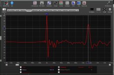
I was making a mistake, saying the 200Hz wavelet measured with a slightly shorter period than the expected 5ms.
Here's a 200Hz wavelet carefully measured in the middle of a sufficiently wide bandwidth not to filter it.
As can be seen, 2 periods are 10ms, as expected.

My apologies...i reran experiments super careful, because prior 200Hz results just didn't make sense.
Also reran slowly moving the wavelet frequency into where it becomes filtered by xovers. The measured wavelengths change very predictably, ala what Mark, Ron, (and myself) have been thinking.
I was making a mistake, saying the 200Hz wavelet measured with a slightly shorter period than the expected 5ms.
Here's a 200Hz wavelet carefully measured in the middle of a sufficiently wide bandwidth not to filter it.
As can be seen, 2 periods are 10ms, as expected.
My apologies...i reran experiments super careful, because prior 200Hz results just didn't make sense.
Also reran slowly moving the wavelet frequency into where it becomes filtered by xovers. The measured wavelengths change very predictably, ala what Mark, Ron, (and myself) have been thinking.
I've continued to play with wavelets for low frequency timing work and remain super impressed with their repeatable accuracy.
But that's not the point of this post...
Just want to share how well, how easily, REW also works for this.
Screen shot shows the Signal Generator and Scope.
I used Channel 1 of my soundcard as mic channel for capture [CH1], and set Scope to trigger off CH1 with rising edge.
Then simply click on 'Single' which Arms the trigger and turns on the Recorder for a single shot take like with a regular scope.
Press Play on Generator with whatever Tone Burst you've set.
Done...that easy.
Quite a cool little scope really, cursors and all...nice job REW ! 🙂

I am kind of confused with this. Normally, to find out delay, I would use two channel measurement with a loopback (or the Acoustic reference feature). The scope in Rew can be used in single channel mode e.g. with UMIK-1? I would think this is not possible. If I undestand it correctly, the scope triggers from Ch1 input and the time will have its zero always at the beginning of the recorded wavelet - or will it count the time actually from when the signal starts being sent to the USB device?
Scopes normally trigger on a timebase at a point along the vertical scale. This is done so you can reliably see the result.
I just do not understand how to measure any relative delay when the scope is triggered alway by the recorded signal. I could understand that if the scope was triggered by the loopback.
As I wrote, I am not sure I understand it properly, so that is why I ask. I think the wavelet method can be used only with dual channel measurement, I just need a confirmation if I am right or not.
Hi pelanji, yeah, I'm not sure how, of even if, REW's scope can be used for finding TOF. It does have two channels...maybe triggering off soundcard output on 1st ch and capturing mic on 2nd....dunno at all.I just do not understand how to measure any relative delay when the scope is triggered alway by the recorded signal. I could understand that if the scope was triggered by the loopback.
It's a beautiful scope for looking at a single wavelets, but when i realized there was now way to save and overlay wavelets, I quit working with it.
ARTA's dual channel recorder works great for TOF via wavelets/bursts. And it's files can be exported into REW if there's a desire for a better "scope look"
This one i did in REW, one have to put in 1ms on the most distant driver (in the xover) then swap the result with the one of interrest minus the 1ms (used for a gap) One only need one channel in rew out and in, and can bus to L & R out (in miniSHARC 4x8 for ex).
If the signal is strong enough you can tell the polarity is right also. Be sure to limit the after coming sweep to 1000hz to protect the tweeter. So in this case the tweeter earned a delay of 0.15 (5cm).
If the signal is strong enough you can tell the polarity is right also. Be sure to limit the after coming sweep to 1000hz to protect the tweeter. So in this case the tweeter earned a delay of 0.15 (5cm).
Attachments
Last edited:
Recently, fellow DIYer Tfive had some questions regarding using wavelets or tone bursts, for determining xover delays.
https://www.diyaudio.com/community/...s-and-phase-measurements.384660/#post-6983723
Main question was, for crossovers do we time align bursts' central peaks (or better said, the centers of the bursts),
or do we align the bursts' initial rise from zero.
The correct answer i think everyone came to agree on, is to time align the centers.
Ok, that clearly works for any single xover. And covers time alignment for a two-way.
But what about multi-ways with multiple xovers. Can bursts be used to time together the entire speaker......and how?
What part of the burst would be used for aligning the multiple sections together?
It seemed to me when a speaker is properly aligned, bursts would have to mimic like REW shows bandwidth filtered impulse responses.......
....which is, that all impulse starts rise from zero at the same point in time. (or at least they do when mag and phase are both flat zero).
Starts, not centers for different driver sections.
So to test that, I did a quick FIR-tune-to-a-spot of a Syn10, a 4-way MEH used from 100Hz up, with xovers at 300, 700,and 6300Hz.
To get flat mag and phase, and see what bursts look like.

After playing with both ARTA's and REW's Tone Burst Generators, I came to prefer a single-cycle sine, with uniform windowing in ARTA, and rectangular windowing in REW. These appear to be equivalent, and give easy to read scope traces with a sharp beginning edge regardless of frequency.
It was interesting comparing the raw driver bursts....it gave good info on which driver handled the burst the best at a given frequency, up and down the available xover overlap ranges. For instance, the Syn's low driver reaches fine up to 500Hz, and the mid driver fine down to 200Hz. Anywhere in between could be used. Bursts got worse of the low driver as freq increased, and worse for the mid driver as freq decreased.
Optimal middle ground was probably 275Hz, which is dang close to the 300Hz I've been using.
Anyway, for the purpose of seeing exactly where bursts align on a fully tuned speaker, i ran the following:
These are microphone grabs !...... acoustic output.. Gotta love FIR 😀
Here's a150Hz burst from the middle of the low drivers' range; and a 300Hz burst at the low-to-mid 300Hz LR4 xover frequency.
Note how the starts align up as surmised.

Here's 150Hz; and 700Hz, the mid-to-HF LR4 xover frequency

Same 150Hz; with 6300hz burst at HF-to-VHF LR 96 dB/oct xover.

The starts lined up, no matter what frequency, what driver, entirely in band, or in a xover region.
Again, this is for looking across sections ....not for looking at an individual xover.
For individual xovers, it's back to aligning central peaks or centers.
Here's the three xovers. 300Hz, 700Hz, and 6300Hz.
Note the centers align. And note a sample or so (0.02ms) misalignment on a couple of them ....that's the precision available if one cares.
(The last 6300Hz xover was at the limit of ARTA's resolution.....I should have used higher than 48kHz with soundcard)


Ok, hope that helped explain when to use, what part of a burst, for what task.
Now....how to pragmatically use this.... ime/imo.
I've always had a hard time with time alignments indoors. You have to measure so darn close to keep the room out, that time and phase alignment are inevitably made too close, like a pair of eyeballs focusing up close, when you want them to focus at listening distance.
But good luck trying to make repeatable timing measurement at listening distance with usual sine sweeps or transfer function measurements (good luck with any driver section without sufficient HF content)
This single-cycle uniform/rectangular window nails timing....at distance.....high freq or low. To the sample.
At about 12ft across the room with all kinds of nearby objects, I measured the burst timings of each raw driver section at the intended xover freq.
Then set delays to have then all their bursts' align at starts.
Those delays did not need to be touched, after putting linear phase xovers in place. (well, maybe they need a sample's worth 🙂)
I don't know, but i think that would be true for any complementary IIR xover too.
https://www.diyaudio.com/community/...s-and-phase-measurements.384660/#post-6983723
Main question was, for crossovers do we time align bursts' central peaks (or better said, the centers of the bursts),
or do we align the bursts' initial rise from zero.
The correct answer i think everyone came to agree on, is to time align the centers.
Ok, that clearly works for any single xover. And covers time alignment for a two-way.
But what about multi-ways with multiple xovers. Can bursts be used to time together the entire speaker......and how?
What part of the burst would be used for aligning the multiple sections together?
It seemed to me when a speaker is properly aligned, bursts would have to mimic like REW shows bandwidth filtered impulse responses.......
....which is, that all impulse starts rise from zero at the same point in time. (or at least they do when mag and phase are both flat zero).
Starts, not centers for different driver sections.
So to test that, I did a quick FIR-tune-to-a-spot of a Syn10, a 4-way MEH used from 100Hz up, with xovers at 300, 700,and 6300Hz.
To get flat mag and phase, and see what bursts look like.
After playing with both ARTA's and REW's Tone Burst Generators, I came to prefer a single-cycle sine, with uniform windowing in ARTA, and rectangular windowing in REW. These appear to be equivalent, and give easy to read scope traces with a sharp beginning edge regardless of frequency.
It was interesting comparing the raw driver bursts....it gave good info on which driver handled the burst the best at a given frequency, up and down the available xover overlap ranges. For instance, the Syn's low driver reaches fine up to 500Hz, and the mid driver fine down to 200Hz. Anywhere in between could be used. Bursts got worse of the low driver as freq increased, and worse for the mid driver as freq decreased.
Optimal middle ground was probably 275Hz, which is dang close to the 300Hz I've been using.
Anyway, for the purpose of seeing exactly where bursts align on a fully tuned speaker, i ran the following:
These are microphone grabs !...... acoustic output.. Gotta love FIR 😀
Here's a150Hz burst from the middle of the low drivers' range; and a 300Hz burst at the low-to-mid 300Hz LR4 xover frequency.
Note how the starts align up as surmised.
Here's 150Hz; and 700Hz, the mid-to-HF LR4 xover frequency
Same 150Hz; with 6300hz burst at HF-to-VHF LR 96 dB/oct xover.
The starts lined up, no matter what frequency, what driver, entirely in band, or in a xover region.
Again, this is for looking across sections ....not for looking at an individual xover.
For individual xovers, it's back to aligning central peaks or centers.
Here's the three xovers. 300Hz, 700Hz, and 6300Hz.
Note the centers align. And note a sample or so (0.02ms) misalignment on a couple of them ....that's the precision available if one cares.
(The last 6300Hz xover was at the limit of ARTA's resolution.....I should have used higher than 48kHz with soundcard)
Ok, hope that helped explain when to use, what part of a burst, for what task.
Now....how to pragmatically use this.... ime/imo.
I've always had a hard time with time alignments indoors. You have to measure so darn close to keep the room out, that time and phase alignment are inevitably made too close, like a pair of eyeballs focusing up close, when you want them to focus at listening distance.
But good luck trying to make repeatable timing measurement at listening distance with usual sine sweeps or transfer function measurements (good luck with any driver section without sufficient HF content)
This single-cycle uniform/rectangular window nails timing....at distance.....high freq or low. To the sample.
At about 12ft across the room with all kinds of nearby objects, I measured the burst timings of each raw driver section at the intended xover freq.
Then set delays to have then all their bursts' align at starts.
Those delays did not need to be touched, after putting linear phase xovers in place. (well, maybe they need a sample's worth 🙂)
I don't know, but i think that would be true for any complementary IIR xover too.
Mark, you have problem reading at sweet spot? I have great succcess with a 48v microphone.
Showing mid bass with 1ms temporary expander on mid. (3meter)

Showing mid bass with 1ms temporary expander on mid. (3meter)
While trying to grasp this thread thisfar, one question: sounds, like music are transient by nature.
Our hearing for discrimination of sound, distance etc uses wavefront in the Loes and en envelope in the highs.
So should we not time align wavefront in lows with envelope in highs?
(Group delay is about relative time dif between envelopes. )
Our hearing for discrimination of sound, distance etc uses wavefront in the Loes and en envelope in the highs.
So should we not time align wavefront in lows with envelope in highs?
(Group delay is about relative time dif between envelopes. )
Well i think the sound for delay setup is somewhere above 1khz and all drivers should be able to send it if one bypass the filters.
Mark, you have problem reading at sweet spot? I have great succcess with a 48v microphone.
Showing mid bass with 1ms temporary expander on mid. (3meter)
View attachment 1040831
Hi viper_user, I'm not really understanding what you've done.
What two divers, or sections, are those impulses from? What were the passband ranges they covered?
And what was the stimulus signal...looks like normal sine sweep?
The thing is, with linear view impulses, each single frequency gets one vote as to where peak impulse timing is. So HF/VHF dominates the timing of the linear view impulse peak, and that's not what we need to time lower frequency sections.
We need lower frequency sections impulses alone, representative of the passband they will be operating in....to see where they begin, not peak.
Ime, impulse responses that cover significantly more higher frequency bandwidth than the driver section will be used for, don't work well for time & phase alignments. Unless peering into the driver section's bandwidth-filtered impulse response that decently matches up with the intended passband.
The starts rising from zero, of those filtered impulses need to be time aligned.
Aligning peaks across driver sections causes misalignment........that's what i hoped to show with my prior wavelet post.
Sure, I can catch decent sine-swept impulses at distance in a room, with repeatable TOFs (time of flight, aka excess delay, etc) provided there is enough HF energy...like at least up to 1000Hz.
But for subs, or low mid drivers, repeatability suffers, more and more as passband frequency range decreases.
That's why I'm so thrilled with the single-cycle tone burst for time alignment across sections....its repeatability is rock solid.
I knew i could use the bursts repeatability for xover alignments, e.g. sub to low, with greater accuracy than either phase overlay or filtered-impulses. (aligning burst centers.)
But until recent experiments, i didn't realize how accurate and repeatable the bursts work for timing across driver sections. (aligning the bursts' starts).
Hi Jan,While trying to grasp this thread thisfar, one question: sounds, like music are transient by nature.
Our hearing for discrimination of sound, distance etc uses wavefront in the Loes and en envelope in the highs.
So should we not time align wavefront in lows with envelope in highs?
(Group delay is about relative time dif between envelopes. )
I don't think the nature of music has much to do with how our reproduction system needs to work.
I think the reproduction system's task is to linearly reproduce whatever waveforms are fed into it.
Linear reproduction comes from a system such that a full range impulse, like a balloon pop, gun shot, lightning strike, etc, ....have every frequencies' wave start from zero time and amplitude, at the same time. So envelopes are a by product of that timing, not the timing determinant.
Well our hearing has no clue (technically) if it is reproduction or production. It is how it works w.r.t. to the frequencies aspect of pressure variations entering our hearing system.
Group delay is about delay differences between adjacent envelopes of frequencies. But the length of envelopes covering a given number of tones varies with frequency. I hope i state it clearly.
Group delay is about delay differences between adjacent envelopes of frequencies. But the length of envelopes covering a given number of tones varies with frequency. I hope i state it clearly.
Last edited:
- Home
- Loudspeakers
- Multi-Way
- Neat way to find delay, phase, and polarity at xover