Started working on this before xmas but found a transistor blown (Q430) so had to wait for the parts-condition dim light tester on
issue +24v on right speaker terminal
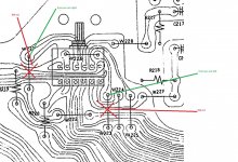
so far as attached drawing
-no voltage on Q420 so checked R456 was open circuit-replaced
Q420-faulty-replaced-dim light tester now off
R470-tested one leg lifted-ok
R476-tested one leg lifted-ok
with both lifted at the same time-still 24v on terminal
zener's D432 and D434 one leg lifted on each at the same time-still 24v on terminal
R516-tested one leg lifted-ok has 1.5v one side 24v the other
i cant see where else i would get 24v from? something ive missed maybe?
issue +24v on right speaker terminal
so far as attached drawing
-no voltage on Q420 so checked R456 was open circuit-replaced
Q420-faulty-replaced-dim light tester now off
R470-tested one leg lifted-ok
R476-tested one leg lifted-ok
with both lifted at the same time-still 24v on terminal
zener's D432 and D434 one leg lifted on each at the same time-still 24v on terminal
R516-tested one leg lifted-ok has 1.5v one side 24v the other
i cant see where else i would get 24v from? something ive missed maybe?
Begin by checking the rails. These use a switched higher voltage supply to the output stage for high level output and are known as a Class G amplifier. In the NAD they can give trouble but as long as either the normal low supply is present or the higher supply then the amp would work.
D422 and D424 are the important 'commutation' diodes. The low voltage (low being a relative term here) is fed into D 422 for the positive rail. Lets say its 30 volts DC. That 30 volts DC appears on the cathode of the diode and so feeds the output stage with 30 (less the diodes 0.6 volts drop). The negative side works the same way.
When a loud bit comes along the transistors above that diode turn on (they are just configured as a high current switch) and then Q432 is turned on and puts the higher supply (lets say 45 volts) onto the output stage. Diode D422 is then reverse biased because the cathode is then more positive than the anode and so the higher voltage rail takes over.
Typical faults are the commutation diodes going open circuit and/or the transistor switch going short circuit. As long as you have either 30 or 45v (I'm guessing the voltages) and the corresponding -30 or -45 then the amp would work.
If you have +24 volts on the output then check those 15k 1 watt resistors as a first step R448 and R450
Yes ")
Basic test depending how its configured is to just check the voltage across the Zener is close to the marked value. Within 20% is fine.
Zener's are like ordinary diodes except that they deliberately 'break down' in a controlled non destructive way and begin to conduct current when they are reverse biased. So a 12 volt Zener when reverse biased begins to pass current when the voltage across it reaches 12 volts. An ordinary diode would withstand the voltage up to its max rating and then it would fail and if the current was high enough it would fail destructively. Zener's are designed to operate in that breakdown region without damage.
So Zener's are used as simple voltage references.
Within 20% is fine.
Well maybe 10%. 20% is a bit wild really but they are not very precise and the exact voltage also depends how much current we put through them.
ok i understand what you are saying thanksBegin by checking the rails. These use a switched higher voltage supply to the output stage for high level output and are known as a Class G amplifier. In the NAD they can give trouble but as long as either the normal low supply is present or the higher supply then the amp would work.
D422 and D424 are the important 'commutation' diodes. The low voltage (low being a relative term here) is fed into D 422 for the positive rail. Lets say its 30 volts DC. That 30 volts DC appears on the cathode of the diode and so feeds the output stage with 30 (less the diodes 0.6 volts drop). The negative side works the same way.
When a loud bit comes along the transistors above that diode turn on (they are just configured as a high current switch) and then Q432 is turned on and puts the higher supply (lets say 45 volts) onto the output stage. Diode D422 is then reverse biased because the cathode is then more positive than the anode and so the higher voltage rail takes over.
Typical faults are the commutation diodes going open circuit and/or the transistor switch going short circuit. As long as you have either 30 or 45v (I'm guessing the voltages) and the corresponding -30 or -45 then the amp would work.
If you have +24 volts on the output then check those 15k 1 watt resistors as a first step R448 and R450
so this ended up being a mirror image failure, not sure why but i suddenly had this idea it could be the same the other side as i had +voltage on the neg rail.
so i tested those resistors and they were fine so i went backwards and R468 had failed along with Q422.
so the repair equated to
R466 and R468 failed and replaced
Q422 and Q420 failed and replaced
Q430 failed and replaced
Ignore post #1 stating R456 failure it was a dislexic moment and it was the other channel i was looking at(and should have been R465 anyway) still it wouldnt be me if i didnt put something down wrong at some point
my guess is it was over driven perhaps
ill check back once ive completed the checks and set the bias etc
Well done
Something you could try for interest on these and it involves using the scope and that is to check the switched Class G rail operation. The voltage on D422 and D424 should be the low supply voltage supply from C505 and C506 in the power supply. That voltage feeds the output transistors.
So in any case you should check that is OK with a meter and that you have the same 'low' voltage on each side of those diodes.
The high supply comes from C509 and C510 in the power supply. That should not appear (yet) on the output transistors. If you connect the scope to the speaker output and connect the signal generator to an input and set it to say 1kHz you should see a clean sine at the speaker output. Now monitor the supply voltage on D422 cathode with your meter and slowly turn up the volume. You should see the DC voltage feeding the output stage (on D422) suddenly switch to the higher voltage supply. The same should happen for the negative rail.
Good eh
(The transistor switches can often fail short circuit if the output transistors have failed so it should always be part of the checks)
ok i will do thatWell done
Something you could try for interest on these and it involves using the scope and that is to check the switched Class G rail operation. The voltage on D422 and D424 should be the low supply voltage supply from C505 and C506 in the power supply. That voltage feeds the output transistors.
So in any case you should check that is OK with a meter and that you have the same 'low' voltage on each side of those diodes.
The high supply comes from C509 and C510 in the power supply. That should not appear (yet) on the output transistors. If you connect the scope to the speaker output and connect the signal generator to an input and set it to say 1kHz you should see a clean sine at the speaker output. Now monitor the supply voltage on D422 cathode with your meter and slowly turn up the volume. You should see the DC voltage feeding the output stage (on D422) suddenly switch to the higher voltage supply. The same should happen for the negative rail.
Good eh
(The transistor switches can often fail short circuit if the output transistors have failed so it should always be part of the checks)
one problem though at the moment
ive set the idle and centre up, no problem there
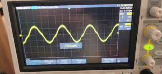
one thing though, no output at all from either channel with and input from CD player, and i have hum from the speakers, this doesnt change at all with the volume control, just one constant volume
could this improve if i convert it to have a mains earth?
ive checked all the grounding, and thats all good, i think its transformer hum as it is humming a bit so its possibly that
pictures of hum attached
Attachments

Do you mean no output from just the dedicated CD input while other inputs such as Tuner, Tape and Video are OK? If so then its a pure physical/mechanical issue somewhere with either the selector switch or breaks in the print. That should be easy to trace with the scope,
The hum is hard to say because it depends how loud it is. 50 Hz hum suggests either a ground loop somewhere or induced hum (stray pick up). Transformers can radiate their magnetic field and do this.
It all depends on what is normal for those amps and whether what you have is excessive and a problem.
If it was power supply related it would be more likely 100Hz (because of the bridge rectifier) and much more spiky looking.
its one constant volume, almost exactly like you would hear if you were to have the phoo connected to the turntable without the ground wireDo you mean no output from just the dedicated CD input while other inputs such as Tuner, Tape and Video are OK? If so then its a pure physical/mechanical issue somewhere with either the selector switch or breaks in the print. That should be easy to trace with the scope,
The hum is hard to say because it depends how loud it is. 50 Hz hum suggests either a ground loop somewhere or induced hum (stray pick up). Transformers can radiate their magnetic field and do this.
It all depends on what is normal for those amps and whether what you have is excessive and a problem.
If it was power supply related it would be more likely 100Hz (because of the bridge rectifier) and much more spiky looking.
its not normal for these amps as i have one and it makes no noise at all, you can hear it humming
i do have a spare transformer,they are like gold dust for the amps
no sound output with cd playing, in any input, so ill have to look for a break somewhere
Look at the CD problem first because that should be easy to find and it may well be related to the hum.
If the amp has an unknown history it could be a break in the print from being whacked or dropped. Use the scope. Set the generator to give say 1 volt peak to peak at 1kHz and connect that to the CD input. Then just follow the signal through. Check the ground connection of the input sockets are intact as well.
If the amp has an unknown history it could be a break in the print from being whacked or dropped. Use the scope. Set the generator to give say 1 volt peak to peak at 1kHz and connect that to the CD input. Then just follow the signal through. Check the ground connection of the input sockets are intact as well.
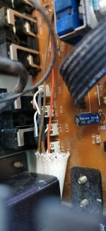
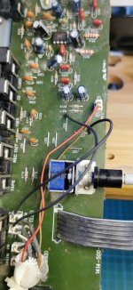
well when i connected the scope i couldnt realy see anything, then the noise itself gave the clues, 'like a phono without the ground', so i started looking for anythings that looked like a bad connection, but couldnt find anything realy, so then i started to look at the wiring and saw those 2 connections
not sure what purpose that mod was supposed be, who ever did it didnt need to do anything if they wanted to use it as a pre/power amp only all it did was disconnect the pre amp, but leaving the ground in place without the supply was where the noise came from
not sure what purpose that mod was supposed be, who ever did it didnt need to do anything if they wanted to use it as a pre/power amp only all it did was disconnect the pre amp, but leaving the ground in place without the supply was where the noise came from
Oh I don't know, I'd have to disentangle it all. Could they have been trying to bypass the selector switch and feed an input straight onto the volume control but then they could have been thinking all sorts doing something like that. Maybe they didn't know what they were doing and got stuck.
You'll probably never know.
You'll probably never know.
Very true.
And as they are an unknown it is worth checking them from a safety aspect as well. Make sure the fuses are correct values and that nothing has been bodged around the mains switch such as shorting one side out to overcome a failed switch. That is a very common tactic and very dangerous.
And as they are an unknown it is worth checking them from a safety aspect as well. Make sure the fuses are correct values and that nothing has been bodged around the mains switch such as shorting one side out to overcome a failed switch. That is a very common tactic and very dangerous.
- Home
- Amplifiers
- Solid State
- NAD 3240pe-high terminal voltage