Hi all,
I recently bought a 300w sub with a broken power board for 15 quid.
I stripped out the power board and the fancy low pass filter, frequency modulator, and volume control board out. Then bought an L7 MOSFET mono power board that supports 300-350 W at 8 ohms as well as requiring 2x 50 V in, this is exactly what the transformer outputs and what the driver requires.
I also picked up a 2M ohm potentiometer for volume control and a 100Hz or so highpass/lowpass filter (i always get it the wrong way round)
because it's a mono out board I'm having a lot of trouble trying to work out how to correctly wire it all?
Any help?
Finlay.
(https://www.ebay.co.uk/itm/221254643945?_trkparms=amclksrc=ITM&aid=1110006&algo=HOMESPLICE.SIM&ao=1&asc=20200818143230&meid=f1091f7470794e6eb76178fa92c156f5&pid=101224&rk=2&rkt=5&sd=224405663394&itm=221254643945&pmt=1&noa=1&pg=2047675&algv=DefaultOrganicWeb&_trksid=p2047675.c101224.m-1 link for power board)
(https://www.hifigear.co.uk/epos-els-subwoofer.html link to sub)
I guess 2Mohm is too high for Volume control. Try a lower value say 10-20kI also picked up a 2M ohm potentiometer for volume control
I think the pots that were with the original were 2M Ohms, but ill try to run it without a volume control.I guess 2Mohm is too high for Volume control. Try a lower value say 10-20k
However, i still have the problem of having 0 idea how to wire it.
any suggestions?
I think it wants 50V DC not AC. Is that what you mean? I'd also say they are a bit optimistic on the power spec of 300+ W from a 50V rail into 8 ohms.
ON the spec sheet it says it requires 50V AC definitely. I agree that the power output is optimistic but for 15 pounds i couldn't resist, it should at least work however to a degree.I think it wants 50V DC not AC. Is that what you mean? I'd also say they are a bit optimistic on the power spec of 300+ W from a 50V rail into 8 ohms.
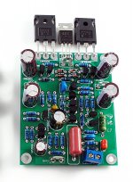
This amplifier board requires a +/- DC power supply. Looks like up to +/-70 VDC max.
The line below that says "it requires AC 50V(or below)x2" is simply a mistake.
One of the power input terminals is visible in the photo and labeled +Vss.
Also, there are no power supply components on the board.
If you apply AC to this board you will destroy most of the transistors instantly.
From the posted link:
******************************************
Features
L7 mono MOSFET audio amplifier board kit.
Kit only, you need to weld all components by yourself.
Parameters:
Output power of 150W 8R DC + - 56V
300W 4R DC + - 56V
350W 2R DC +-45V
Frequency range 4HZ-3DB, 350K HZ-3DB
THD <0.01% 100W 1K HZ
SR = 38V/US
SNR> 99DB
it requires AC 50V(or below)x2, or DC ±70V(or below), 100W(or above) transformer.
Complementary feedback input stage using CFP. Single-ended voltage amplification.
CLASS AB class work.
PCB size = 78 * 63 MM
Output stage features Germany VISHAY IRFP240, IRFP9240 FET output
Use advanced MKP coupling capacitors.
Use floating MOSFET driver, designed by LJM.
PCB identification number on a detailed, user-friendly installation. Only need to install the corresponding parts on related positions..
Please note that the insulation must be installed under transistor IRF610, must use insulating films, insulating particles.
Package include:
amplifier board kit x 1(include 1 board PCB and all the components on the picture.)
kit only, you need solder it by yourself.
NO INSTRUCTION COME WITH THE ITEM.
(components values have been marked on the PCB, NO schematic will be attached)
Manufacturer may use different (from the picture) but same grade components due to different bulk. Please consider if you can accept it before buy.
Attachments
Or perhaps what they mean by this is that, for the DC power supply you will need a transformer with 2 50V AC secondaries (or below) to make a DC supply of +/-70 VDC (or below).it requires AC 50V(or below)x2
And furthermore, all the output power specs reference a wattage based on a +/- DC supply voltage.Output power of 150W 8R DC + - 56V
300W 4R DC + - 56V
350W 2R DC +-45V
Please post photos of the all the parts you have in order to get help with the wiring. Thanks.However, i still have the problem of having 0 idea how to wire it.
any suggestions?
Well I will have unfortunately already fried the board, as tested it already, I did think it was a tad odd how small the board was. When I powered it up however there was no smoke or smell of burning plastic so it may not be.This amplifier board requires a +/- DC power supply. Looks like up to +/-70 VDC max.
The line below that says "it requires AC 50V(or below)x2" is simply a mistake.
One of the power input terminals is visible in the photo and labeled +Vss.
Also, there are no power supply components on the board.
If you apply AC to this board you will destroy most of the transistors instantly.
From the posted link:
******************************************
Features
L7 mono MOSFET audio amplifier board kit.
Kit only, you need to weld all components by yourself.
Parameters:
Output power of 150W 8R DC + - 56V
300W 4R DC + - 56V
350W 2R DC +-45V
Frequency range 4HZ-3DB, 350K HZ-3DB
THD <0.01% 100W 1K HZ
SR = 38V/US
SNR> 99DB
it requires AC 50V(or below)x2, or DC ±70V(or below), 100W(or above) transformer.
Complementary feedback input stage using CFP. Single-ended voltage amplification.
CLASS AB class work.
PCB size = 78 * 63 MM
Output stage features Germany VISHAY IRFP240, IRFP9240 FET output
Use advanced MKP coupling capacitors.
Use floating MOSFET driver, designed by LJM.
PCB identification number on a detailed, user-friendly installation. Only need to install the corresponding parts on related positions..
Please note that the insulation must be installed under transistor IRF610, must use insulating films, insulating particles.
Package include:
amplifier board kit x 1(include 1 board PCB and all the components on the picture.)
kit only, you need solder it by yourself.
NO INSTRUCTION COME WITH THE ITEM.
(components values have been marked on the PCB, NO schematic will be attached)
Manufacturer may use different (from the picture) but same grade components due to different bulk. Please consider if you can accept it before buy.
Thanks so much for your help, I'm out rn but will send pictures over later, thanks again 🙂Please post photos of the all the parts you have in order to get help with the wiring. Thanks.
- Home
- Design & Build
- Construction Tips
- Subwoofer wiring confusion