Help with Rotel 802
- By Clare.Rotel
- Solid State
- 16 Replies
I have a Rotel RX 802 which was given to us by a relative along with some Leak Speakers and a dual 504 turntable. All which were used together but have been in storage for at least 5 years.

We've spent weeks trying to get it all working; sometimes it works fine (and sounds amazing!) and other times it doesnt, so I'm thinking its a connection issue somewhere. We've replaced the speaker wires and the 2pin and 5pin connectors.
The issues that we have are (sometimes individually and sometimes all at the same time),
1.) A buzzing on 1 or both speakers
2.) 1 or both speakers not working
3.) 1 speaker louder than the other
4.) Speakers working but playing very quietly
We love the equipment and really want to get it working rather than buying new!
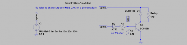
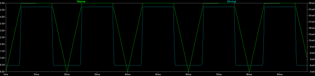


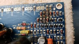
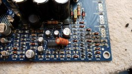
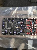
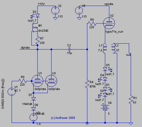
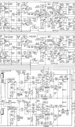
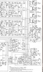
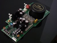
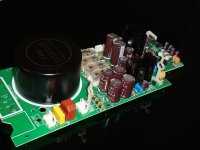
 ) I managed to short either a resistor or a diode.
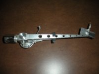
![XTC_04[1].jpg](/community/data/attachments/949/949929-8d81cb185db83f79d6929d72dec0e9e7.jpg?hash=jYHLGF24P3)
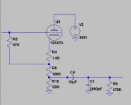
![XTC_03[1].jpg](/community/data/attachments/949/949930-7556b94159440f74176e90309cfd8a1a.jpg?hash=dVa5QVlED3)
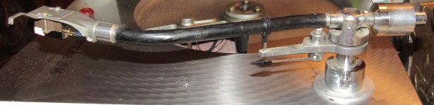
![XTC_02[1].jpg](/community/data/attachments/949/949931-f1d2eb599a2e2454edaf4deb2f1694a1.jpg?hash=8dLrWZouJF)
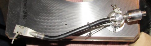
![XTC_01[1].jpg](/community/data/attachments/949/949932-8b703c00414c71324a41f87e23c7a0ef.jpg?hash=i3A8AEFMcT)


