My audio chain consists of a USB DAC -> Active Filter -> Amplifiers -> Speakers.
There are frequent power failures, that result in a loud bang that could potentially damage my ears and the speakers. I suspect that the USB DAC is the culprit. The USB DAC is powered by a 5V linear PS.
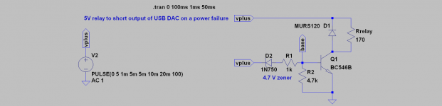
I was wondering if a relay to short out the outputs of the USB DAC on a power failure would limit the damage. I can introduce a 100 ohm resistor in the shorted paths to limit the output current.
The 5V relay I am considering is the Omron G5V-1 (5V, 30 ma, 176 ohms).
Can you please review my scheme and suggest improvements? The zener diode will be 3.6V in the implementation.
Thanks
There are frequent power failures, that result in a loud bang that could potentially damage my ears and the speakers. I suspect that the USB DAC is the culprit. The USB DAC is powered by a 5V linear PS.
I was wondering if a relay to short out the outputs of the USB DAC on a power failure would limit the damage. I can introduce a 100 ohm resistor in the shorted paths to limit the output current.
The 5V relay I am considering is the Omron G5V-1 (5V, 30 ma, 176 ohms).
Can you please review my scheme and suggest improvements? The zener diode will be 3.6V in the implementation.
Thanks
Attachments
Last edited:
In my view, it is likely to be the USB DAC that collapses first, when mains power is lost, and then disturbs the input of the amplifier. You can try this out by replacing the DAC with two 100 Ohm resistors to ground, one for each channel. Does it then make a lot of noise when you pull the mains power plug for the rest of the system?
If not, you know a solution to the problem.
Your relay idea is fine. You just have to make sure the relay reacts faster than the DAC collapses. By using the same +5V voltage as for the USB DAC, I am not sure you will manage. When mains power is lost, there is a delay until the +5V collapses and the DAC makes noise. You should rather let the relay work on a voltage that reacts quickly to the loss of main power.
What about a relay operating directly on the mains power?
What is the mains voltage in India?
Last edited:
Thanks for your reply.
My DMM measures 243 VAC, so I'm not sure of the RMS value.
I need to experiment your idea of the 100 ohm shorts, and think some more on the points you have made.
My DMM measures 243 VAC, so I'm not sure of the RMS value.
I need to experiment your idea of the 100 ohm shorts, and think some more on the points you have made.
What most manufacturers do is power a relay from a rectified AC secondary winding with a low value tank capacitor that discharges quicker, when the power fails, than the tank capacitors collapse the power supply. Disconnecting the Loud Speaker and if you like, mute the output from the DAC.
What most manufacturers do is power a relay from a rectified AC secondary winding with a low value tank capacitor that discharges quicker, when the power fails, than the tank capacitors collapse the power supply. Disconnecting the Loud Speaker and if you like, mute the output from the DAC.
I believe you even have 230V/240V AC coil relays so you can control such a relay directly from the mains voltage. Electromagnetic relays have mechanical inertia that do not allow them to react on 50/60Hz signals. That may be the simplest and still fast reacting.
If the DC smoothing caps for the USB DAC are drained quicker than the <10ms a relay would need to react, you've got bigger problems 😀
It can be done in mains circuit using a relay and 2 push buttons it is a
start stop retain relay control circuit ( see internet )
but you will need a relay with a coil voltage for your mains parameters
start stop retain relay control circuit ( see internet )
but you will need a relay with a coil voltage for your mains parameters
First step is to confirm if the DAC is indeed the cause of the power down thump/crack.
If so, a ready solution is to use a USB power injector and external supply....portable battery recharger works well.
Dan.
If so, a ready solution is to use a USB power injector and external supply....portable battery recharger works well.
Dan.
I tested with shorted inputs to the (analog) active filter, and can confirm that there was no thump/bang on a power off. So it's the USB DAC that needs a relay solution.
I can also confirm what Max Headroom mentioned about a battery powered USB DAC. Earlier, the USB DAC was powered by the laptop and there were no issues on a power off. I introduced an external 5V linear regulated power injector to the DAC to minimize the laptop's PS noise, and subsequently this issue cropped up.
I can also confirm what Max Headroom mentioned about a battery powered USB DAC. Earlier, the USB DAC was powered by the laptop and there were no issues on a power off. I introduced an external 5V linear regulated power injector to the DAC to minimize the laptop's PS noise, and subsequently this issue cropped up.
PS description
transformer secondary 0-12 VAC, 24 VA
bridge rectifier
CRC filter (4700uF + 220R + 4700uF)
LM7805 regulator
USB cable hacked to inject 5V from the regulated PS. The Vcc from the laptop side USB is connected to ground with a 1K resistor.
transformer secondary 0-12 VAC, 24 VA
bridge rectifier
CRC filter (4700uF + 220R + 4700uF)
LM7805 regulator
USB cable hacked to inject 5V from the regulated PS. The Vcc from the laptop side USB is connected to ground with a 1K resistor.
take 2
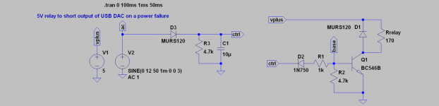
I read the ESP article on the mute circuit, and here's my second iteration. Please review and let me know any gotchas.
I used an available 12 VAC transformer for the 5V PSU, which is now being considered for the relay control circuit as well in the schematic.
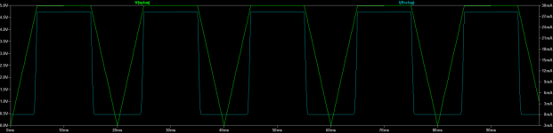
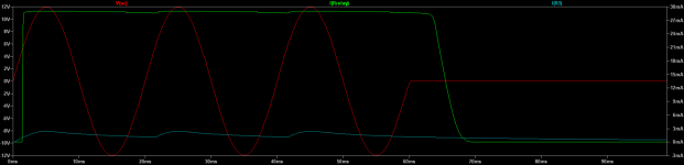
I think if reality reflects the simulation, the relay turns off in less than 10ms, which I assume is reasonable.
I read the ESP article on the mute circuit, and here's my second iteration. Please review and let me know any gotchas.
I used an available 12 VAC transformer for the 5V PSU, which is now being considered for the relay control circuit as well in the schematic.
I think if reality reflects the simulation, the relay turns off in less than 10ms, which I assume is reasonable.
Attachments
Why so complicated?
Why not use a 12 volt ac relay across the 12 ac of the transformer? When energised the contacts are open, when the power is off or fails, the contacts close and silence the amp.
Why not use a 12 volt ac relay across the 12 ac of the transformer? When energised the contacts are open, when the power is off or fails, the contacts close and silence the amp.
Yes, 12 VAC relay is probably the best solution. I'll start looking for an inexpensive one, but in the meanwhile, I can build and test the proposed schema with parts on hand. Thus a review would be beneficial.
AC relay noise?
I got the 12V AC relay, but I had a doubt... Would the AC coil introduce EMI noise in the low level signals? I can see the contact wires close to the AC coil inside the relay.
Can folks share their experience if they have used this approach?
Thanks
I got the 12V AC relay, but I had a doubt... Would the AC coil introduce EMI noise in the low level signals? I can see the contact wires close to the AC coil inside the relay.
Can folks share their experience if they have used this approach?
Thanks
If output impedance of USB-DAC is low enough it will not radiare much noise.
In some very precision devices - sure, AC-coil can be a problem.
In some very precision devices - sure, AC-coil can be a problem.
Revisiting this topic to understand.
Can someone explain or point to information as to what exactly happens when power is removed? What kind of output waveform is created on a power failure? I want to understand the event in the following 3 cases:
1. USB DAC - powered by a 5V regulated power supply; typical output is 1V peak
2. Active Filter - powered by regulated dual rail power supply 15-0-15 V; typical output is 2V peak
3. Power amp - powered by dual rail power supply 27-0-27 V; output load is 8 Ohms
Thanks
- Home
- Amplifiers
- Power Supplies
- Relay protection on power failure