OSVA - Open source Versatile Analyzer
- By Frex
- Equipment & Tools
- 184 Replies
Hello all,
First, for the first release of the OSVA project, i start this new clean thread to avoid confusion.
This first post will be used in future to see major projects changes.
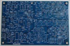
The OSVA is an new high performance analyzer that use SAR ADC from Linear-Technology/AD (LTC2380-24).
This project is born to follow up of my previous works done with the LT eval board and an CPLD eval board.
All information about this can be found on this previous post here :
SAR ADC for high performance audio ADC project [LTC2380-24]
So now, after some time of silence i keep you informed about project progress.
That has took more time than expected, time to learn Kicad too (and now Altium at work, Yuck!).
I do that only in spare time an i'm very busy at work right now).
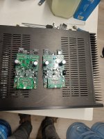
Anyway, i now have finalized the PCB routing and i have ordered it to manufacturer (WEdirekt).
It will be on my desk, ready to start soldering in about ten days now.
From the previous schematics posted, i made several improvements.
I try to list them here :
Low noise regulators for ADC are replaced by LT3042 (as suggested by...).
OPA1632 (SOIC8 FDA from Ti, lw noise).
THS4541 (High speed ultra low THD from Ti).
I planed at first time to use the ADA4945 that promised extremely low THD level, but the latest datasheet release
show much worse THD level so i will use preferentially the THH4541.
As this project is fully open source, you can get all project files in it's new GitHub repo here :
OSVA - Open Source Versatile Analyzer
Complete new schematic can be found here (pdf) :
Github AA2380v1.00 pdf file.
Thanks to Kicad, you can also see how it will look like when populated. 🙂
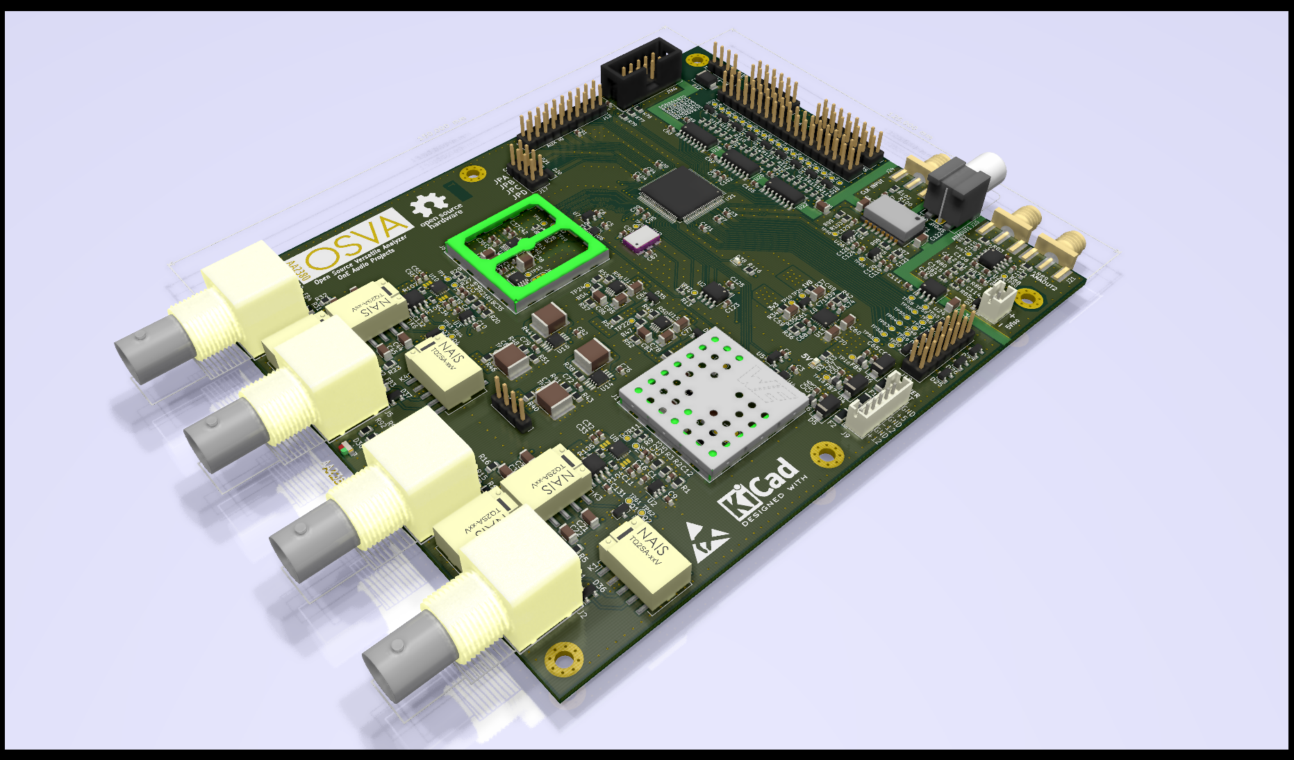
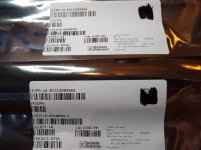
Now, i must order some missing parts to Mouser (a complete bom ready) to ready when i receive the board.
There is some works to be done on others PCBs of the project:
- Front panel control board (leds and rotary encoder)
- AAPSU Power supply board (+5 and +/-Vanalog).
- AA10M08 Digital Logic board (Digital filtering and display interface).
I must also seriously work on CPLD software.
I hope to give others new soon. To be continued...
Regards.
Frex
First, for the first release of the OSVA project, i start this new clean thread to avoid confusion.
This first post will be used in future to see major projects changes.
The OSVA is an new high performance analyzer that use SAR ADC from Linear-Technology/AD (LTC2380-24).
This project is born to follow up of my previous works done with the LT eval board and an CPLD eval board.
All information about this can be found on this previous post here :
SAR ADC for high performance audio ADC project [LTC2380-24]
So now, after some time of silence i keep you informed about project progress.
That has took more time than expected, time to learn Kicad too (and now Altium at work, Yuck!).
I do that only in spare time an i'm very busy at work right now).
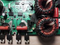
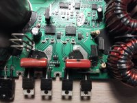
Anyway, i now have finalized the PCB routing and i have ordered it to manufacturer (WEdirekt).
It will be on my desk, ready to start soldering in about ten days now.
From the previous schematics posted, i made several improvements.
I try to list them here :
Low noise regulators for ADC are replaced by LT3042 (as suggested by...).
- I added 2 isolated analog output from PWM signals for external oscillator synchronization (enable coherent FFT).
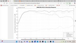
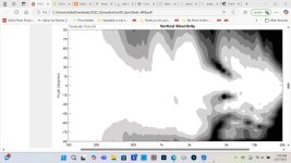
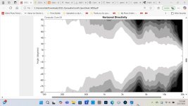
- The Input buffer LPF include two cutoff frequencies : 38.4kHz and 384kHz by default (they can be customized if required).
- The inputs can be switched to single-ended or differential mode.
- The input buffer is designed to use (at least) one this three buffers :
OPA1632 (SOIC8 FDA from Ti, lw noise).
THS4541 (High speed ultra low THD from Ti).
I planed at first time to use the ADA4945 that promised extremely low THD level, but the latest datasheet release
show much worse THD level so i will use preferentially the THH4541.
As this project is fully open source, you can get all project files in it's new GitHub repo here :
OSVA - Open Source Versatile Analyzer
Complete new schematic can be found here (pdf) :
Github AA2380v1.00 pdf file.
Thanks to Kicad, you can also see how it will look like when populated. 🙂
Now, i must order some missing parts to Mouser (a complete bom ready) to ready when i receive the board.
There is some works to be done on others PCBs of the project:
- Front panel control board (leds and rotary encoder)
- AAPSU Power supply board (+5 and +/-Vanalog).
- AA10M08 Digital Logic board (Digital filtering and display interface).
I must also seriously work on CPLD software.
I hope to give others new soon. To be continued...
Regards.
Frex

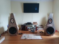

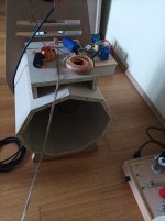
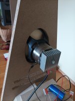


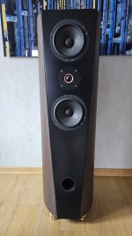
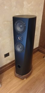
 Assuming you have a source of wood and carbon fibre, the only things slightly out of the ordinary are the neodium magnets, which are fairly ubiquitous on the web.