Hi. I got a small amp with 12 V trigger in (3.3 or 5V will not do) and a Raspberry Pi 4B with a dac hat and running camilladsp and a USB gadget mode, UAC. Works well enough so that I want to make use of the 12 V trigger. The problem is that I'm a newbie with low level electronics, although I have some basic understanding on how things work. I have also assembled diy duplos (Hypex NC400 kits) and they work well. I asked ChatGPT, but it gave conflicting answers. I need a human confirmation so that I won't fry my devices.
I now know that the 12 V and 3.3 V rails on the Pi have good current output so that they can easily handle trigger signal through a step-up converter (that I have) and some other small components. However those rails cannot be controlled with software, they are always on. The togglable GPIO pins supply 3.3 V, but very little current. Less than 20 mA I think. The AI gave two possible solutions.
1) A relay: 5V -> relay -> step-up -> amp, control relay by a GPIO pin. I don't have such relay, but there should be RPi/Arduino compatible relays available everywhere.
2) Using an NPN transistor or a MOSFET. I happen to have a small electronics kit that came with TO-92 (?) packaged NPN transistors that are labeled as "PN2222". AI says they're good. Print on the actual component says "2N 2222A -1726". The guide goes like this:

This result conflicts with what the AI was telling for legs. With the flat side of the transistor facing me (down in the pic), the legs should be from left to right: EBC, right? It's difficult to see in the pic, but that's how they go into the testers numbered slots. Anyway I see the letters NPN, so it's correct type?
Low power consumption is a requirement, because I'm on USB 2 power budget and I got other devices to connect too. At this point I feel like the relay would be a better idea, but I kind of hoped to make with stuff that I already have. What say you?
PS. I'm also developing UI with a small OLED screen and a rotary encoder, but this trigger is higher on my priority.
I now know that the 12 V and 3.3 V rails on the Pi have good current output so that they can easily handle trigger signal through a step-up converter (that I have) and some other small components. However those rails cannot be controlled with software, they are always on. The togglable GPIO pins supply 3.3 V, but very little current. Less than 20 mA I think. The AI gave two possible solutions.
1) A relay: 5V -> relay -> step-up -> amp, control relay by a GPIO pin. I don't have such relay, but there should be RPi/Arduino compatible relays available everywhere.
2) Using an NPN transistor or a MOSFET. I happen to have a small electronics kit that came with TO-92 (?) packaged NPN transistors that are labeled as "PN2222". AI says they're good. Print on the actual component says "2N 2222A -1726". The guide goes like this:
- transistor emitter to ground
- 5V supply pin to transistor collector
- 10 kOhm resistor between transistor base and ground
- selected GPIO pin to transistor base through 1 kOhm resistor, this is the programmatically controlled pin for toggling on/off
- ground to step-up converter in-
- transistor collector to step-up converter in+
- when GPIO pin is high (3.3 V), it should allow current flow to the step-up converter and produce me 12 V trigger (when voltage is adjusted correctly).
This result conflicts with what the AI was telling for legs. With the flat side of the transistor facing me (down in the pic), the legs should be from left to right: EBC, right? It's difficult to see in the pic, but that's how they go into the testers numbered slots. Anyway I see the letters NPN, so it's correct type?
Low power consumption is a requirement, because I'm on USB 2 power budget and I got other devices to connect too. At this point I feel like the relay would be a better idea, but I kind of hoped to make with stuff that I already have. What say you?
PS. I'm also developing UI with a small OLED screen and a rotary encoder, but this trigger is higher on my priority.
I have a similar setup—a Raspberry Pi with an 8-channel PCM5102A DAC running CamillaDSP.
I used a step-up converter to generate 12V, but instead of using a GPIO pin, I used one of the USB-A ports. I cut a USB cable to access the +5V and GND wires, connected them to the step-up converter, and then connected four cables with 3.5mm mono jacks to each of the four Fosi ZA3 amplifiers. The USB port is disabled when the Pi shuts down (or goes into standby). As soon as you press the wake-up button, the USB port powers up, and the amplifiers turn on.
It works, but there’s one issue: it’s incredibly noisy! At least in my setup, I need to add a DC filter. Maybe the step-up converter I used is just too cheap.
The step-up converter that I am using is this one:
https://pt.aliexpress.com/item/4001027643593.html
https://pt.aliexpress.com/item/4001027643593.html
Be aware that many of these regulator chips are being faked now, and run at lower frequency with rather a lot of noise.
I discovered this the obvious way, in an amp build, and instead of the TI datasheet levels of noise I got lots of whistles etc.
Personally I'd go for a relay and then switch your choice of 12V through it, then you can always use an analog source for the 12V if nothing else works well enough.
I discovered this the obvious way, in an amp build, and instead of the TI datasheet levels of noise I got lots of whistles etc.
Personally I'd go for a relay and then switch your choice of 12V through it, then you can always use an analog source for the 12V if nothing else works well enough.
Don't use AI for something like this because it doesn't actually know the answer - use actual human sources who have written actual knowledge and experience down which you can learn from.

https://electronics.stackexchange.c...ide-transistor-switching-with-microcontroller
See High Side Switch fig 2.
Note, the 'load' is the amp trigger input.
For safety you can add a resistor in series with the amp trigger input.
This will limit current should the trigger lead be left unconnected and touch where it shouldn't.
The current required for the 12V trigger should be tiny (consult your data sheet); a 1K resistor would limit the current to 12ma in event of a short.
You can also get really clever and add LEDs with series resistors to show when 'active' or 'standby'.
Thanks for input. I decided to get a large optocoupler and hook that up with a current limiting resistor like you suggested. The opto seems to draw less from the GPIO and provides more isolation. I planned to also attach a switch for hw-off if necessary.
I need time to plan it through and source some components, but I will post back here. I haven't seen too many guides how to do this with RPi, although it had been asked many times.
I need time to plan it through and source some components, but I will post back here. I haven't seen too many guides how to do this with RPi, although it had been asked many times.
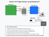
Hello everyone! I’m new to this forum, but I struggled with exactly the same issue and I finally solved it, using kind of both solutions presented here (USB cable to power the 12v trigger port combined with a relay). Here is the solution I posted on another forum from the OS manufacturer for my network streamer. I’m not a native english speaker, so I asked an AI to polish my explanation:
This circuit allows a Raspberry Pi running Volumio to automatically turn on an amplifier when music starts playing and turn it off when music stops, using the amplifier's 12V trigger input.
### Components Used
1. Raspberry Pi running Volumio OS
2. TIP31C NPN power transistor
3. 1.2kΩ resistor
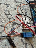
4. 5V relay module
5. USB cable (cut open to access power wires)
6. 3.5mm mono jack cable (to connect to amplifier's 12V trigger input)
### Connections Explained
#### Raspberry Pi to Transistor/Relay Circuit
- GPIO 17 → 1.2kΩ resistor → TIP31C Base (B)
- 5V pin (GPIO 2) → Relay module VCC
- GND pin (GPIO 9) → Relay module GND and TIP31C Emitter (E)
- TIP31C Collector (C) → Relay module IN
#### USB Cable to Relay Contacts
- COM terminal on relay → 3.5mm jack TIP (one wire)
- NO terminal on relay → USB 5V (RED wire)
- NC terminal on relay → USB GND (BLACK wire)
- 3.5mm jack SLEEVE (other wire) → USB GND (BLACK wire)
### How It Works
1. When Music Starts Playing:
- Volumio sets GPIO 17 HIGH
- This activates the TIP31C transistor
- The transistor completes the circuit for the relay coil
- The relay switches from NC to NO
- This connects the 3.5mm jack TIP to 5V (USB red wire)
- The 5V potential between TIP and SLEEVE triggers the amplifier
2. When Music Stops:
- Volumio sets GPIO 17 LOW
- The TIP31C transistor stops conducting
- The relay returns to NC position
- This connects the 3.5mm jack TIP to GND
- Both TIP and SLEEVE are now at GND (0V difference)
- The amplifier detects this and turns off
### Key Advantages of This Solution
1. Overcomes Current Limitations: Uses USB power which can provide more current than GPIO pins alone
2. No External Power Supply Needed: Everything is powered from the Raspberry Pi
3. Compatible with 12V Trigger Systems: Most amplifiers with "12V trigger" inputs actually work with 5V signals
4. Galvanic Isolation: The relay provides electrical isolation between the Pi and the amplifier
5. Simple Implementation: Uses common, inexpensive components
### Notes for Implementation
- Ensure the relay module is a 5V type (most common ones are)
- Double-check the TIP31C pinout (E-B-C from left to right when looking at the flat side)
- Verify which wire in the USB cable is +5V (typically red) and GND (typically black)
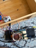
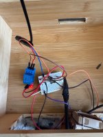
- This solution can be implemented on a small breadboard and housed inside your Volumio enclosure
This solution is elegant because it uses the USB port's higher current capability while still being controlled by the low-current GPIO pin, solving the problem without needing a separate power supply.
This circuit allows a Raspberry Pi running Volumio to automatically turn on an amplifier when music starts playing and turn it off when music stops, using the amplifier's 12V trigger input.
### Components Used
1. Raspberry Pi running Volumio OS
2. TIP31C NPN power transistor
3. 1.2kΩ resistor
4. 5V relay module
5. USB cable (cut open to access power wires)
6. 3.5mm mono jack cable (to connect to amplifier's 12V trigger input)
### Connections Explained
#### Raspberry Pi to Transistor/Relay Circuit
- GPIO 17 → 1.2kΩ resistor → TIP31C Base (B)
- 5V pin (GPIO 2) → Relay module VCC
- GND pin (GPIO 9) → Relay module GND and TIP31C Emitter (E)
- TIP31C Collector (C) → Relay module IN
#### USB Cable to Relay Contacts
- COM terminal on relay → 3.5mm jack TIP (one wire)
- NO terminal on relay → USB 5V (RED wire)
- NC terminal on relay → USB GND (BLACK wire)
- 3.5mm jack SLEEVE (other wire) → USB GND (BLACK wire)
### How It Works
1. When Music Starts Playing:
- Volumio sets GPIO 17 HIGH
- This activates the TIP31C transistor
- The transistor completes the circuit for the relay coil
- The relay switches from NC to NO
- This connects the 3.5mm jack TIP to 5V (USB red wire)
- The 5V potential between TIP and SLEEVE triggers the amplifier
2. When Music Stops:
- Volumio sets GPIO 17 LOW
- The TIP31C transistor stops conducting
- The relay returns to NC position
- This connects the 3.5mm jack TIP to GND
- Both TIP and SLEEVE are now at GND (0V difference)
- The amplifier detects this and turns off
### Key Advantages of This Solution
1. Overcomes Current Limitations: Uses USB power which can provide more current than GPIO pins alone
2. No External Power Supply Needed: Everything is powered from the Raspberry Pi
3. Compatible with 12V Trigger Systems: Most amplifiers with "12V trigger" inputs actually work with 5V signals
4. Galvanic Isolation: The relay provides electrical isolation between the Pi and the amplifier
5. Simple Implementation: Uses common, inexpensive components
### Notes for Implementation
- Ensure the relay module is a 5V type (most common ones are)
- Double-check the TIP31C pinout (E-B-C from left to right when looking at the flat side)
- Verify which wire in the USB cable is +5V (typically red) and GND (typically black)
- This solution can be implemented on a small breadboard and housed inside your Volumio enclosure
This solution is elegant because it uses the USB port's higher current capability while still being controlled by the low-current GPIO pin, solving the problem without needing a separate power supply.
Attachments
-
 396f7a8e-26de-405e-8af7-da56ce7bc108.jpeg118.9 KB · Views: 64
 -
 IMG_3884.jpeg195.6 KB · Views: 62
 -
 IMG_3878.jpeg891.1 KB · Views: 57
 -
 IMG_3877.jpeg766.8 KB · Views: 57
 -
 IMG_3884.jpeg195.6 KB · Views: 48
 -
 396f7a8e-26de-405e-8af7-da56ce7bc108.jpeg118.9 KB · Views: 59
 -
 IMG_3878.jpeg891.1 KB · Views: 56
 -
 IMG_3877.jpeg766.8 KB · Views: 41
 -
 IMG_3869.jpeg1.3 MB · Views: 53
 -
 IMG_3868.jpeg930.8 KB · Views: 56
- Home
- Source & Line
- PC Based
- 12 V trigger from a Raspberry Pi, using step-up converter