motor unit noise

Hey fellow DIYers!

I'm having an issue with the motor unit I'm building for my all-DIY-turntable.
Currently I use a mason DCX 22 motor in an external motor unit built of alloy. The motor itself runs w/o vibrations - but it is quite noisy. I can still hear it from about 2m of distance.

So my question is: What measures can I take to reduce the noise of the motor in the motor unit? Do you know of any materials that I could use to reduce the noise?

Ideas would be gladly appreciated
Stephan

Takman Rex vs Rey

I'm finishing a 6SN7, line-level preamp. I used Takman REY, metal film resistors in the signal path. A friend listened and suggested that using Takman REX carbon film might enhance the sound: make it less clinical, more tubey.

I respect his ear but, who knows? (Sure: the Shadow knows.)

Any thoughts or experiences worth sharing?

Need advice on outputs on a Sound Valves VTA70i

Hello All and thanks for the add.
I recently received 2 of these amps and I have re-capped both and set them up as mono-blocks per their instructions.
They sound pretty dang good to my ears.
My question; can I or should I change the EL34 tubes (I learned them as tubes, long time ago!) for KT66?
I have heard all kinds of stories, and viewpoints and I am just wondering it they would 'help' in any way?
The KT66s would be the Gold Lion which has some good review.
I would appreciate any info - just getting back into audio......

DIY MID HIGH Peter Morris

SOLD!!

A pair of Peter Morris DIY Mid High tops in 90deg version is up for sale.

Fil_000(3).jpg

See the NEW DIY Mid High thread for further details or call me or PM me.

2 x 12 RCF MB12N351 in a folded horn and 1.4 BMS 4594 HE Coax.

This is a 3 way/2 way active top that sounds fantastic and goes very loud.
They are less than 35kg.
Pole mount.
Recessed handles.
Black Tuffcab Pro.
NL4 Speakon
106 db/2.83v
LowMid: 1300 AES /2600 Peak.
MidHigh: 150 AES/1500 Peak
High: 80 AES/320 Peak

I have made DSP settings both IIR and FIR(no phase correction) for Powersoft K series. The amps can be bought with the speakers.

I have used them with 2 Xoc1 TH-18 tapped horns per side. The subs are also for sale.

PM me for measurements and more pictures.

The speakers are located in Denmark, but shipping is ok, if arranged by the buyer.

IMG_0024.jpg

Fil_000(1).jpg

IMG_1110.jpg

Cheers. Andy

A few mods to my LP12

Hi all. I have been planning a few diy upgrades for my Sondek for a while so I thought I should share the plans and see what you all thought. I'm still in the design phase so there is plenty of opportunity to refine it. The updates will be done in a month or two. I have a few parts to make first and also waiting for delivery of a motor from Maxon.

The turntable is presently a fairly basic spec unit. I fitted a new AC motor and made an Armageddon clone drive for it earlier in the year. Also made a prototype aluminium sub chassis and re-wired the arm, which is a REGA RB202. Sound quality is ok but it clearly has a long way to go. There is some vibration from the motor so must be affecting the performance a lot.


The next round of upgrades have been in design for around 6-months. I stripped and measured the turntable an re-created it in CAD (Creo). I have used this to design new parts and assess them using Creo Simulate FEA. When I looked at the standard LP12 design I was surprised how basic it is and there are several poor features and a lack of stiffness in the structure and sub-chassis. Upgrades from Linn are so very expensive and just fix their own crap design features! My plan has been to match or improve some of those upgrades for a fraction of the cost.


I will put a few more posts on to show details. There are 4 main upgrades; new tonearm, subchassis, fix top plate resonance, and add a decent DC motor with closed loop voltage control. I'm hoping these will give good performance and get me rocking with the old vinyl collection. 🙂


Picture below shows one of the problem areas that I have been looking at and assessing loads of design options - subchassis. The standard pressed steel subchassis looks poor and the analysis confirms this. It weighs around 1.1kgs and there is a further 3.7kgs of weight on it from the platter and tonearm. This weight makes is resonate at a low frequency. There is a first order resonance of just 52Hz. This cant be very good for bass performance!

Attachments

  • Standard subchassis.JPG
    Standard subchassis.JPG
    83.5 KB · Views: 582

XO upgrade?

In 1998 I built a 2-way speaker from a kit I bought. The tweeter is a ScanSpeak D2905/970000,and the midwoofer is an AudioTecnology 5H 52 17 06 SD. Back then it was something of the top and it is still very nice drivers.

The XO was designed by someone who knowing what he was doing, I believe, and it generally has good components in it. The coils are the flat CFC air coils, and the 2 capacitors direcktly in the tweeter line are Mundorf Supreme. The capacitor in parallel with the bass is however, only a M-cap also from Mundorf. The resistors are a bit of a mystery. These are 3 very different resistor types. There is a 47 ohm which bypasses the large coil for the bass so it sits in a direct line. It's a metal one with a heatsink 25W. It is unfortunately gorn off the one XO so it has been replaced by an M-Resist from Mundorf 20W. Then there is a 2.2 ohm which bypass a capacitor to the tweeter and it is a very strange resistance. It's such a small plastic RCH resistor. Finally, it is an old-fashioned sandcast resistor parallel to the bass.

What I intend to upgrade the XO a bit is to replace the last 2 resistors with M-Resist. Sandcast is in any case a somewhat inferior resistance than M-resist the price is in any case below 10%. But that RCH resistance is in Denmark quite expensive, but it is a good resistance. I think there must be a reason why the designer chose it. In addition, I will
Bypass the 2 supreme capacitors that are in direct line with the tweeter, with a 0.01 µF silver-gold-oil from Mundorf. The reason for that it is Mundorf I mention, is that they are the ones I have good access to. I'm just trying to see if I can figure out how to put one image of the XO.

TUNG-SOL KT120 and KT150 valves

.
Apart from a fairly marginal difference in terms of Cathode Filament Current and a Plate Dissipation of about ten Watts in favour of the KT150, from an electrical point of view (Anode Voltage, Impedance, Transconductance etc.), the TUNG-SOL KT120 Power Pentodes and the more recent TUNG-SOL KT150 are practically the same.
.
KT120.jpg

.
But since I'm very keen to experiment with the newer sisters on my Single-Ended amplifier currently equipped with KT120s, I wanted to ask those who have already experimented with them about any contraindications of use, but above all about their differences in terms of general musicality.
.
KT150.jpg

.
I thank in advance all those who would like to share and contribute their experience.

Test stand for loudspeaker measuring

I ran into the problem of my usual tripod beeing to weak for a new speaker I was building.
So I first thought about building a new one by my self. Anyway, this would have been a week long project for it self, getting the materials, designing it retracable for storage etc.
At a local discounter I ran into a stand for bike repairs. To cut a long story short, for the 50$ it's regular price was, I would not even been able to buy the steel tubing used. It even was at close out sale for 20$...
Fixing a platform for the speaker from some spare wood was done in a few minutes and I was ready to measure. I do measure speakers in the open if weather permits, so such a solid piece of equipment is great for the garden. The model I picture here is identical to mine and really heavy steel at ca. 15lbs/ 7.5kg. Secure speaker position can be as high as 5 feet/ 1.6 meter, which makes for a microfone position at 1.8-2 meter.

A bonus: If you do not measure speaker, it is a great help for bike repairs, adjusting gear change mechanism and converting bikes to E-bikes.

A professional loudspeaker stand is another option, but the ones with a wind up mechanism, which I would prefer, are much more expensive.

Attachments

  • bike stand.jpg
    bike stand.jpg
    8.9 KB · Views: 69
  • bike stand1.jpg
    bike stand1.jpg
    44.9 KB · Views: 79

Should I get one 18" or two 12" for my 3-Way?

Hi there,

Let's start from these assumptions:
  • F3 is tuned at ~24hz for both.
  • Xmax within range.
  • Fully active 3 way, no passive crossover.
  • The 18" has +3db compared to the two 12" below 28hz, so it get's lower... but again, DSP here.
  • box size doesn't matter.
  • they will cut at 260hz.

pros/cons?
Anyone experienced both?
Modern speakers have multiple woofers, I get that, commercial thing, the general public likes them more for the look and space vs the fridge sized speaker... but would they sound "better" with a bigger woofer?

Acoustic modification of concert venue

Working on a 5,000 set concert venue beside the casino at Niagara Falls. The concert hall was completed a few years ago but never opened because it failed the acoustics test (too much echo) and we're changing the angle of the panels at the back of the theater. He's some photos of the work.
The panels are made of 6 pound fiberglass. Resin is poured on in patches so that we can screw on the clips that will suspend the panels. They are being changed from being flat against the wall to angled towards the stage. 3 layers of 3" mineral wool insulation is stuffed behind the panels. This was done on all 4 floors.
Behind the stage 2 layers of 3" mineral wool were placed on the wall behind the performers and large walls of insulation are going to be built on the catwalk above the stage.
Holes were cut into the ceiling to let the sound escape into. The angled panels hide the holes.
I've also included a couple of pictures of the finished product.

Real itchy work, it was a lot more fun building the actual venue! Cold as hell but at least I wasn't covered insulation fibers all the time!!

20220728_114837.jpg

Attachments

  • 20220808_145825.jpg
    20220808_145825.jpg
    286.3 KB · Views: 161
  • 20220803_081732.jpg
    20220803_081732.jpg
    394 KB · Views: 157
  • 20220803_081521.jpg
    20220803_081521.jpg
    455.7 KB · Views: 160
  • 20220802_143749.jpg
    20220802_143749.jpg
    493.1 KB · Views: 155
  • 20220728_082116.jpg
    20220728_082116.jpg
    487.5 KB · Views: 152
  • 20220728_082050.jpg
    20220728_082050.jpg
    283.5 KB · Views: 149
  • 20220728_081920.jpg
    20220728_081920.jpg
    356.5 KB · Views: 157
  • 20220728_082001.jpg
    20220728_082001.jpg
    376 KB · Views: 150
  • Like
Reactions: Pano and JMFahey

Musical Instrument Waveform Generator with Amplitude Correction

Seems all the waveform generators available, whether PC based or stand alone, do not permit automatic amplitude correction. Here's the issue: using an electric guitar, my low E produces an output of about 250mV immediately after the pick strike, while the note on the 22nd fret of the high E string chimes in at 100mV.

Is there a way to sweep through all the guitar frequencies, or any musical instrument, while simultaneously correcting the amplitude? I know it's possible to build one, I just want to purchase something. Battery powered preferred.

It may not make a difference in most situations, but if one were to build a speaker cabinet and test it, would not a constant amplitude possibly yield erroneous results? For instance, say a 2kHz signal at an amplitude that will never be achieved in a real world scenario, causes a resonant frequency to oscillate the cabinet, or otherwise ruin the natural speaker response.

Distance from speaker to listener / frequency response

Hi

Wondering if there is any science to what I am hearing here. When I have a 2 way speaker, lets called it a nearfield or bookshelf. At around 3.5 feet everything sounds great, there is a certain continuity between 2-5k that is seamless and present. When I back up to about 4.5-6 feet some of this clarity goes away, a lot of it actually.

This is happening to me in different well treated rooms, different monitors, at different orientations of drivers/cabinets.

Beyond phase alignment and bad reflections from the room, is there anything that would change frequency response with distance?

Is there a different approach for a speaker that will be listened to at a distance of 6-8 feet than one that might be listened at 3-4 feet?

I am a little confused, tempted to take them outside to see if its all just room reflections becoming more prominent and the perception of less upper mids and if I am crazy.

Dan

Amp per voice coil?

Good day everyone - hope you’re all doing well!


Buchardt Audio came out with a Signature Edition of their A500, with a custom Purifi woofer for the front driver (has 2 voice coils) with 2 separate amps powering the same woofer

I’m curious what the benefit of that would be?
Guessing it’s to do with one of their custom voicings - in cardioid mode, they likely lose some output, so the extra voice coil+amp would be used to compensate for that loss?
(Being that the rear driver would be used for cancellation to create the cardioid pattern?)


Regardless - I’m just curious if there’s other benefits to that approach (dual voice coils+dual amps feeding the same driver) beyond an increase in output?


Thank you all in advance!

Potentiometer with filament bias DHT

Hello, I am building a 71a preamp, and it's coming along pretty well!
Right now I have about a 19V filament supply, and a 56R/12W resistor and it dials in the filaments almost exactly at 250mA and 14V bias. Works great!
But 100 year old tubes are impossible to match, and I was thinking of swapping the 56R for a 75R/12W and then putting a 500R/5W power rheostat or variable resistor in parallel. Or alternatively, keeping the 56R resistor and then putting a 20R power variable resistor in series.

This way I can match the tubes, or also play around with starving the filaments a bit to see what happens. I have a quantasylum distortion analyzer, so I can watch in real time and tune them carefully enough.

Thoughts on this, and also what types of variable resistors are good or bad for this application?

Thanks!

  • Locked
F.S. Mark Audio & Fostex and more .

6-1-22 (UpDate). A few pairs gone. Still a lot to get rid of. I just wanted to add that it’s best if you want a pair of drivers shipped you send me a pre-paid shipping label. Buyer pays shipping. Also I have gotten a few pm’s about really be low average price offers. I don’t mind lowering a price or working with anyone but, $200.00 dollars for a pair of Fostex Fe208Ez drivers. I will go as low as $400.00 brand new plus you get A extra driver. Thanks for a few that bought and traded with me.

Good Evening everyone. I’m trying to clean house and I have a lot of drivers that I never used? Funny I just kept buying and lost track over the last few years. 😬. All drivers are brand new and have never been used what so ever. So am going to do something I have never done before to get rid of my drivers fast. You tell me what’s a fair price per. Pair and we can go from there? I can provide pictures upon request. Shipping is on the buyer and only to the 48 United States please. Local pick up is also available. Please Pm me or e mail me at Jmboo1922@gmail.com

1. Mark Audio drivers for sale.
CHN 70, CHP-70-P, CHR 70 ( in gray 2 pairs of these drivers ), Pluvia 7P, Pluvia 11 in Gold, CHR 90 in gray,
CHN 110 in Gray, CHR-70 in black and the CHR 70 in black paper.

Fostex drivers for sale.

FE83NV, FE103NV, FE208NS, FE108EZ, FE208EZ, FF225WK.

Other Full range driver’s.

Scan Speak 3 inch full range drivers,
SB Acoustis, Aura Whispers, Tang Band 3 inch poly driver’s, fountek 3 inch a Aluminum drivers( cheaper one’s). Peerless 3 inch Aluminum driver’s, A few tectonic drivers.

Other none Full-range drivers for sale.
1. fountek ribbons Neo 3’ the bigger ones, and 7 inch paper drivers, peerless 6 1/2 inch paper drivers.

Please let me know if your interested? You can buy one set or a few no limited quality or you can make me a offer for all my speakers for sale? It’s a buyers market.
  • Like
Reactions: hottube

F.S. Sound easy 27 and other programs. Up for trades as well.

Good morning Everyone. So here are the programs am selling used.

1.Sound easy 27 I have cd and usb key.
2Bass box pro and cross over pro. I have cd and both books in almost mint condition.
3. Winspeakerz program and book. Almost in mint condition.
4.Monacor CAAD program with cd and Install instructions.
5.Subwoofer tool box program. I have the cd.

Selling due to limited time now with my hours at work. E mail me or PM me. Am up for trades as well as payments in Money. Thanks Jeff

Technics SA-202

In the process of replacing bad caps on a SA-202 and have so far replaced all caps visibly bad and corroded. Issues were both channels dropping, weak out put, and occasional R channel dropping.

After replacing bad caps, but not big output caps, still have R channel dropped with very low output with AUX input. Switched to Phono input and both channels sound great. So now I'm on to checking Jack's and plugs, but if anyone has any other ideas, I would be appreciative!

I don't have a strong grasp of circuit theory and ability to interpret a circuit diagram, however I can solder well and can read a DMM if I'm told where and what it should read. Still learning.

Cheap and simple 4-channel power amp without DSP

Hi,

I don't have much experience building amplifiers, but I would really like to build a compact 4-channel power amp for active crossovers.
I would really like:

  • No built in DSP (clean simple signal path)
  • Proper connectors or screw connectors on the board(s) as opposed to JIT
  • Pop protection
  • Auto standby (or at least very low idle power draw)
  • At least two channels of 30-40 watts for bass duty (tweeter channels can be less)

I've looked a bit at the Sure AA-AB32231 for the tweeters channels and a TPA3255 board for the woofer channels.
Or just a 4-channel TPA3255 board (but hard to find one with proper connectors and not JIT)

Any recommendations and/or ideas?

Technics SE-9600 makes noise when turning off

Hi guys.
Today I received a Technics SE-9600 amp from a friend. When turning off the unit, there is a humm present for a while, and a squishing noise that rises in pitch until it's gone. It drives my friend crazy...
Could that be an issue with the relay? Or maybe the ginormous 10.000uF / 80V electrolytic caps? I replaced all caps except those in the past.

Opera Consonance Calaf Mk2 arc sounds after pluging in while power button was on

I have a consonance calaf mk2 that smells like burnt electronics and it makes small popping/arc sounds when i turn it on. It started after i plugged the power cord into the wall with the power button set to on. The fuse in my house blew, and when turning it on again the amp startes having these issues. The amp works just fine, but i dont want to use it before i Get this fixed. Anyone experienced this before?

Attachments

  • 64A1F9AF-1529-4D44-90CD-91D32D06E559.jpeg
    64A1F9AF-1529-4D44-90CD-91D32D06E559.jpeg
    433.9 KB · Views: 81
  • F4292C1F-03E8-41A5-90C1-AB54245CFE7D.jpeg
    F4292C1F-03E8-41A5-90C1-AB54245CFE7D.jpeg
    278.7 KB · Views: 84
  • E501326C-275F-4160-9430-DEF4786F5470.jpeg
    E501326C-275F-4160-9430-DEF4786F5470.jpeg
    458.4 KB · Views: 90
  • 5F8AA8F3-D2C7-4620-B0BC-22A023641608.jpeg
    5F8AA8F3-D2C7-4620-B0BC-22A023641608.jpeg
    423.3 KB · Views: 84

60 hz hum, right channel, Elekit TU-8200 (non-dx)

Hello everyone:
I have a elekit tu-8200 (non-dx). After years of stellar service, the amp has developed what seems a 60hz hum in the right channel. It is not very loud but is is there (it was not there before).
The hum is independent of the volume knob, and exists with nothing at the inputs.

I swapped the opt and no change. Swapped pre-amp tubes, no change. Swapped output tubes, no change.
It seems a component at this point. Any pointers?
Thank you for all and any info you can provide.
Marco
p.s. I am a kit builder, not a DIY self-er...

Class D repair help please, 3525, IR2110, IGBT

Hello to you all, I've been looking round the net for Class D help and this forum looks like the right place.

I've been repairing pro-audio amps on and off for years now but have only recently started seeing more Class D, I 've repaired a few with simple problems and a couple of small chip amps but I've decided now to learn as much as possible about Class D and associated SMPS. I have a non functional Peavey IPR 1600 as a study subject. I'll attach the schematic and a couple of scope traces.

Ok when the amp arrived it had blown the two side B output mosfets (IRF4227) , the IRS2092 (same side) was shorted (not sure about the other at the moment) in the amp and in the SMPS which uses: Q5 (MTP2P50), IC13 (LR654N), IC17 (LM317P), IC14 (555), Q8 (PNP), IC15 (UC3525), IC11 (IR2110) ... the IR2110 was shorted as were the 18v zeners and 5819 schottky diodes on both of the IGBT gates. I expected the IGBT's (STGF19NC60KD) to be shorted too but after close scrutiny they seem to still be functioning properly. Parts arrived and as with all other classes I started on the power supply.

I replaced the IR2110 & both sets of gate zeners and 5819's, then scoped the HO & LO outputs, it was at this point that I realised how unfamiliar I am with these amps.

The LO is showing a switched output but the HO just seems to be DC and there is no switching at the transformer and so no voltage on secondary side.

I've been reading the last couple of days so I see that the HO switching is controlled by the boostrap circuit on VS & VB so I removed all components from this circuit and all test fine so I'm just confused now as to how to troubleshoot the lack of switching on HO. I'm unclear as to whether this is a fault or if it's because of something I have done/not done yet?

Here are IR2110 pin voltages:
VSS = 0v
SD = low
VDD/VCC = 16v
VB = 15.6v
VS = 15v
LIN, HIN, LO, HO are detailed on the scope traces.

If any of you can help me understand how this works properly it would be well appreciated ... attached are the 3525 output traces (so IR2110 inputs) & IR2110 output traces with no switching on HO.

Attachments

Distortion Measurement with Soundcard and ARTA software

While I do have access to Audio Precision test equipment, many times it's much more convenient to do a sound-card based distortion measurement.

Here's a link to a youtube I made that shows an overview of how to do it, along with a schematic for a nice attenuator and limiter that you'll need to use on the input of the soundcard to make power amplifier measurements.

YouTube

Too much gain in EF86

Hello! I introduce myself in this forum that I consider to be very interesting. My question is about the excessive gain of the EF86. I have built a VOX Ac15 schematic circuit and the clean channel has a very high gain and a lot of background noise amplified by this gain. Is it possible to reduce this? Is it normal for it to have a plate voltage of 120 Volts and an anode voltage of 95 Volts? Thank you

Attachments

  • AC15 (3).jpg
    AC15 (3).jpg
    337.1 KB · Views: 1,213

Tang Band W5-1138 as woofer in 2-way setup?

I want to build some near field monitors and I'd like to repurpose some W5-1138s & PT-6818s I have into a stereo BT 2 way setup

I'm happy with the W5s as pure subs but has anyone used them for mid bass? They're def not super efficient but I'm not bothered about that. They do look pretty flat from 50-1kHz, and the planar tweeter supposedly goes down to 500Hz but I would probably cross the two over in the middle at 750Hz. W/the low volumes I generally play at hopefully that wouldn't fry the tweeters. I would also be pairing the W5 with 8" passive radiators (1 of each per channel). Really don't want to mess with any EQing; just want to do simple passive 12db crossovers with attenuation for the tweeters.

Another CFP output design attempt.

...been working on this circuit and something to get my hands busy during vacant days. As I'm getting my grip (and brains) back with LTSpice..please let me know if what I'm doing does not involve redundant parts (and flawed results 🙂).

Closed loop.
CFP_conventional_CLG.png

PM/GM
CFP_conventional_PMGM.png

Step response @ 1KHz & 20Khz
CFP_conventional_1Khz_50W_step.png
CFP_conventional_20Khz_50W_step.png

Clipping point
CFP_conventional_clipping.png

Series of Fourier test at 1Khz 1W / 20Khz 1W / 1Khz 50W / 20Khz 50W (estimated max power)
CFP_conventional_1W_1Khz.png

CFP_conventional_1W_20Khz.png

CFP_conventional_50W_1Khz.png

CFP_conventional_50W_20Khz.png

Schematic
CFP_conventional.png

THD may not be pleasing, I understand it is a Sziklai output..if I wanted to lower THD..H2 level goes down as well (bias current 40ma).

Let me know if the circuit will qualify as a working amp in a real world build.

Thanks!

Tweeter options for Faital Pro midrange?

Halo from Indonesia

I can have a great clearance price on faital pro midrange m5n8 and couple of other faital drivers at my local shop. As they will stop to carry the brand altogether.

The m5n8 is rated 99db sensitivity on their website. Do I need to pair them with higher sensitivity tweeter >> compression driver?

I already have on hand is scanspeak d3004-660000. Will I have trouble pairing the m5n8 with the scanspeak?

I plan to build a 3 way , I was eyeing 12 inch bass driver faital 12pr310 from the same shop.

This will be my first time with PA driver.

Can some one help me wire a tascam DR-10x to a landline to create a voicemail message recorder. Complete newbie.

Basically what I'm wanting to do is make a "Audio guestbook" in the form of a modern rotary telephone.

It's to record messages at events instead of the traditional signed guest book. People pickup the hand piece and leave a message after the beep.

I am wanting to retrofit a phone into a voice message device.

If anyone would be whiling to help me. I would be so grateful. And obviously pay for your time.

Help with T/S parameters Accusound EX-15/2

I am looking at some S/H and cheap woofers simply because they are cheap and as toys to play with.
Seller doesn't have any data
Can anybody here help with data on some old subwoofer drivers from Accusound.
So far the only info is a picture of a sticker on the drivers magnet EX - 15-2 -16R
But at $60- a driver I'm not expecting much. Not picking them up until next month so looking at sims etc before then
Hard paper cone, pressed steel basket and the folded "W" surround typical of Pro-sound gear

LM3886-based Guitar Amp Problems

I originally posted this in a couple of Reddit sub-forums, and it was suggested to try here:

I'm working on a Behringer GX212 guitar amp. While the schematic is for a similar model, the power amp section is identical to what I have. When I received the amp, it had at least one bad output, one was shorted and loudly humming, the other dead quiet. After checking for possible shorts or overvoltage issues, I replaced the electrolytic caps on the power amp board for the 40 and 15 volt supplies, as well as on the I/O lines. I replaced the shorted chip, and now I have two dead quiet outputs. I checked the mute circuit, which I suspected might be an issue. I used a 68K resistor from pin 8 to pin 4 to create a current flow of greater than .05ma, which should disable the mute circuit. It did not change, and I have 40v between pins 8 and 4 without the resistor. The resistors, diode, and transistors in the mute circuit appear to be good, so I'm at a bit of a loss. I'm not sure I should be seeing the 40v at those pins. Link to schematic below. Anyone with more experience able to lend a hand?

Thanks!

Login to view embedded media

Help with Tube Selection

A little help please...I just bought a Chinese, Zero Zone preamplifier that purports to be a Conrad Johnson clone. It has four JJ ECC83S tubes currently. It sounds great! But if I wanted to roll some new/different tubes, what would you recommend? Do I gain anything in a preamplifier design with matched tubes? Sorry, I cant find a schematic anywhere on it's design topography.......Only this quote in the literature..." This preamp is reference the famous conrad-johnson CL Circuit , designed with double-single independent design, physically separated 100% left and right channels, independent hierarchical grounding." Thanks

Attachments

  • P1040730 (2).JPG
    P1040730 (2).JPG
    289.3 KB · Views: 420

Improving a cheap chinese PCM1794 DAC

Sorry if this board was already discussed but I didn't find anything related to it.

I few years ago I paused my diy audio hobby and sold/gifted everything I had built but an year ago I felt the need to start enjoying music once again. In no more than 1 month time I bought the ATC SCM11 curved speakers which I fell in love with at the first note, built a Raspberry Pi 3 + Volumio streamer, built the PeeCeeBee V4H known to most of you and now I was in need of a new DAC which will be used as my main audio source. The requirements were simple:
– Digital input switching. I wanted to use the same DAC whether I am listening from my DIY Volumio streaming device or watching a movie/playing Xbox.
– Good to exceptional sound quality.

After reading an article by a russian author, the PCM1794 datasheet and talking to a friend of mine who works in a professional audio equipment manufacturing company, I decided to try the PCM1794 from Burr Brown for this project. I did a quick search on Aliexpress for readily available PCBs based on PCM1794 and I came across one that looked well made. The PSU part is well separated utilising:
– Four separate transformer windings with 3 bridge rectifiers (MCU+LCD; digital section PSU; analog section PSU)
– Five on board regulators (LM7805 for the uC/LCD, LT1968-3.3V for the AK4118 and PCM1794 digital supply, LM317(5V) for the PCM1794 analog VCC, LM317/337(+-15V) for the opamp supply.
– Utilized ground planes


The board costed only 47$ so I expected cheap capacitors and probably fake AD827 opamps. After 20 days I received the board. I was right, they used cheap caps(except the big filter Nichicons, which seem good) and the opamps are probably fake at this price so I started planning mods to the board.

The first thing I did was to test the board before doing anything so I know if it works as expected. I plugged in all required windings, plugged my set-top box as digital source with an optical cable and flipped the switch…

F**k… The thing is not even working…

pcm1794_chinese_board_pt.jpg


Chinese PCM1794 AK4118 board

The first thing I did was to measure all the supplies. I found out that the LT1968-3.3 had 2.0V at its output so the AK4118/PCM1794 didn’t get enough voltage to work. I desoldered the LT1968 and soldered a LD1117V33. It finally worked. Good thing is I don’t have to return it to the seller and I can start with the mods.

After inspecting the board and following some traces I have annotated the photo of the board of all planned mods for convenience.

annotated_pcm1794_pt.jpg


I have done the following modifications:

1. Change all big diodes in the rectifier bridge to SB5A0 fast recovery diodes because the old ones were standard Chinese diodes with shady letters on them.

2. I checked all resistor values according to the following OPA1611(single version of OPA1612) schematic and found out that the 8200pF capacitors were actually 220pF(marked on board as 820pF) and the 2700pF were actually 270pF(marked on board as 270pF). Resistor values were right according to this schematic.

post-54755-0-23512700-1518607938.png


OPA1612 as I/V converter
Changed those to Wima FKS2 capacitors with the right values and also changed the 2200pF metallized film capacitors in the feedback of the I/V stage with same value Wima FKS2.

3. Changed all electrolytic capacitors to Nichicon UPS which are low impedance, high temp range capacitors suitable for PSU usage. Some of the capacitors were 47uF instead of the 10uF according to the PCM1794 datasheet.

4. The final thing to do was change two of the AD827(probably fake) to two OPA1612 opamps in the I/V stage and change the third AD827 in the differential to single convertor stage to OPA2132.

after_opamps_pcm1794_dac.jpg


I will now let the DAC burn in for a couple dozen hours and I will start listening! The next planned mod is to change all regulators to discrete ones based on a new schematic I am now evaluating. I will combine this DAC in one enclosure with my Volumio streamer and the JLSounds XMOS in the next few days. Any other ideas for possible mods/swaps?

Ale Moglia aka Bartola Valves PCBs

Ordered these a while back. Used a couple to great effect but will not be needing them for future projects.

  • 3x HT supply PCBs @ $15 each
  • 1x Capacitor Multiplier PCB @ $15

Links here:
HT Supply
Capacitor Multiplier

Attachments

  • PXL_20220919_174210416.jpg
    PXL_20220919_174210416.jpg
    506.6 KB · Views: 90
  • PXL_20220919_174200096.jpg
    PXL_20220919_174200096.jpg
    602.7 KB · Views: 84
  • PXL_20220919_174153280.jpg
    PXL_20220919_174153280.jpg
    494.8 KB · Views: 99
  • PXL_20220919_174146867.MP.jpg
    PXL_20220919_174146867.MP.jpg
    677.3 KB · Views: 83

What 3-way design for low SPL listening and good off-axis?

Hey all

I’m not up to required knowledge to start my own design, and am looking to build a 3-way ( or 2-way) that just sounds good. Not interested in faithful reproduction of the recording, just a pair of speakers that make the non-audiophile stop and listen ( basically I need to impress my wife with the sound!), also needing to sound good outside of the narrow sweet spot of the audio triangle.

What I think will get me there are high quality drivers (like scanspeak), and a design with good off-axis performance.

Any thoughts, perhaps one of Troels designs ? This will also need to sound good at low listening volumes too.

Thanks

Need help troubleshooting Audiostatic DCI

Hello and happy new year everyone. I've searched forum and found a few threads that might be relevant to my situation but wanted to ask advice specifically. I've had a pair of audiostatic DCIs since 2007 - these were sent to me in USA as the unfinished (DIY) versions direct from audiostatic. Unfortunately I had a flood event about 7 yrs ago the lower section of the speakers was immersed in water 3 inches or so, for a short while. I can't remember if i tried to play music through them afterwards but I did disassemble for painting and never got around to doing that until recently. Now that's done- on reassembly one speaker plays fine- the other creates a crackling sound on louder volume as you can hear in this video Login to view embedded media I switched the panels out both work fine, and also verified that the 220v transformers is functioning properly so it's something to do with the electronics in that one speaker. I think this may be a defective transformer? I haven't tried measuring as yet to see if any open circuits. Appreciate any thoughts from the experts.

FS: RAAL 70-20XR AM

Hey folks,

Need to downsize my collection and for sale are a pair of RAAL 70-20XR Amorphous Core tweeters. You can see they're mounted in a speaker cabinet for testing, and while I did use them for 10ish hours, life got in the way. They're basically brand new, will include original packaging, and will ship ConUS Priority Mail. Asking $750+shipping for these beautiful tweeters.

See images here: imgur.io/a/SqEefN0. I have 100% eBay feedback (username thedesigner2011 buying and selling) and 25 confirmed trades over on reddit.com/r/hardwareswap also as thedesigner2011. Feel free to reach out with any questions.

Thanks for looking (and listening).

Building a Cyrus PSX

Hi all, I'm looking at trying to make a cyrus psx clone, as far as I can tell its a +/- 38V unregulated supply, and from looking at the innards of my fathers its a 500VA torroid, 4x15,000µF slit foils and then dual rectifiers.

So, that all said I was planning on 4x 22,000µF slit foils [bit pricey], I need to work out what would be suitable diodes, I cant really tell if there would be any real appreciable difference between getting some ultra-fast soft recovery's and using one/ of these GBPC2504 - FAIRCHILD SEMICONDUCTOR - BRIDGE RECTIFIER, 25A, 400V | CPC

The main question finding a transformer that has the necessary 27v secondaries is a bit of a pain, if I use a trafo with 30v secondaries will the 42v output of the PSX cause issues inside of the Cyrus or do I not need to worry about it too much?

Also anyone care to throw any opinions on the idea of bypassing the large slit foils with smaller value caps?

Thanks!

Edit missed this link, but basically I'm just planning to follow the diagram as show here http://sound.westhost.com/psu-wiring.htm and suit it to my needs.

Philips Valve radio capacitor replacement suggestion.

Hi all,

after recent thread by @Elvee I remembered I need to change caps in my Vintage Philips Radio, bought by my dad in 70s. In the past I was told to replace Coupling capacitor. Radio is working somewhat.

Please see attached images. (1) Schematic showing coupling cap position and one elec. capacitor (2) Inside radio actual coupling capacitor shown with red arrow + Blue elec. cap shown (3) A mustard Cap which has tiny part broken at lead. also shown with red arrow.

My question are
1) what type I should use for coupling ? Voltages ? Value tolerance ? Manual says 8K2pf which I suppose is 8200pf. kindly confirm.
2) There is one electrolytic Blue Philips Cap hidden at bottom shown with green color. Should I change that ? What function it serves ? decoupling ?
3) Do I need to change Mustard cap (see pic attached) do they degrade over time ? (Almost 50 years). One has broken portion at lead.

thanks and regards

P.S. : pictures were taken prior to little cleaning.

Attachments

  • schematic.jpg
    schematic.jpg
    310.5 KB · Views: 424
  • coupling.jpg
    coupling.jpg
    396.5 KB · Views: 262
  • Mustard cap.jpg
    Mustard cap.jpg
    89.9 KB · Views: 302

Project: CBT array, balanced DML, delay curved

Hi,

I'm sharing work in progress of a Constant Beamwidth Transducer/Technology ground plane array (CBT) using Distributed Mode Loudspeaker exciter/actuator panels (DML).

66 inch/167 cm straight CBT array using time delay to approximate physical curve shading at -6 dB half-angle: Cosine 47°, Legendre 36°, Chebyshev 25°. Shading (virtual arc) can be reconfigured with the DSP by adjusting the time delay for each bank.

Twelve total actuators per array are positioned 5.5 inches/14 cm center-to-center. The actuators are attached to a wooden spline (hand railing from Home Depot) and excite a poly honeycomb core covered with fabric. One side of the core was left as unmodified fabric. The other side was covered with resin and loose - unwoven - carbon fiber strands then sanded to a flat finish. Each panel is 3 inches/7.62 cm wide and 0.5 inches/1.27 cm thick. They currently use separate panels for each Bank, however, I don't think that's necessary. I think you could do this with one narrow and tall panel with even spacing between the actuators.

(Edit: this paragraph is wrong. Read this post for accurate information Project: CBT array, balanced DML, delay curved) Like Don Keele's CBT-24, this array uses five shaded banks rather than constant shading. Each bank is separately controlled by a DSP channel and each actuator is powered by an amplifier tuned to the same voltage.

I have not taken good frequency measurements with REW. I have taken bad (sloppy) measurements with REW. At present, the array has an unequalized audible resonance between around 1000Hz to 4000Hz with a peak at 2200Hz. It hurts my ears and my dog's ears. I'll equalize it out at a later time. I have only measured the array while Legendre shaded at 36 degrees. I have not measured it while shaded in Cosine or Chebyshev configuration yet.

I've attached photos of work in progress. I will also upload the spreadsheets I used to calculate shading in a second post.

Attachments

  • IMG_20190715_202911704 - Copy.jpg
    IMG_20190715_202911704 - Copy.jpg
    299.8 KB · Views: 581
  • IMG_20190724_165119118 - Copy.jpg
    IMG_20190724_165119118 - Copy.jpg
    300 KB · Views: 515
  • IMG_20190815_125554148 - Copy.jpg
    IMG_20190815_125554148 - Copy.jpg
    437.8 KB · Views: 517
  • IMG_20190815_125726454 - Copy.jpg
    IMG_20190815_125726454 - Copy.jpg
    375.1 KB · Views: 512
  • IMG_20190815_130223682 - Copy.jpg
    IMG_20190815_130223682 - Copy.jpg
    516.1 KB · Views: 513

New CBT Woofers

When I heard the new CBTs at CES, I'd assumed that they were using the Dayton ND65 woofers. But they said they weren't, and that it used a new driver with improvements requested by Don Keele.

I believe the original CBTs did something similar; the Dayton ND91 has more BL and a shorting ring iirc. (It's based on the Dayton ND90.)

So...

Let's see what's going on with the new Dayton ND64, versus the old Dayton ND65.

JAdIPyP.png


wQVS1WZ.png


From a quick look at the spec sheet, it looks like:

1) the new ND64 is cheaper
2) the new ND64 has half the xmax

I'd speculate that what they were trying to do is lower the moving mass. The MMS of the ND64 is 16% less than the ND65. This may contribute to it's high frequency extension.

hzXg2SH.png

It's a bit odd that Dayton overlooked a couple of other drivers in their stable. For instance, the Tectonic Elements TEBM35 has lower mms, flatter response, and lower cost than both the ND64 and the ND65.
(http://medleysmusings.com/tectonic-elements-tebm35c10-4-miniature-bmr-driver/)

Problem with LenearX

Hi,

I have not used the system for a long time, so it happened a couple of days ago, I had to take measurements, and the LinearX system gives an error when measuring the impedance.

Impedance.jpeg

I tried to solve the problem by reinstalling Windows 7, but it did not help. I tried to do internal and external calibration, it also does not help.

Sometimes the system fails internal calibration:

VCA Offset Test (Problem).jpeg

Highlighted in red the item that the system sometimes does not pass.

Thanks in advance for your help.

Shok Industries 5K mono amp

Good day to everyone. I am repairing a Shok Industries Winner series 5k mono amp which had a blown capacitor in the output section.
I was able to removed the blown caps and cleaned the board which is quite difficult which I did not expect. I was surprised that even
with this blown fault the Output transistors and the gate signasl survived so I believed and hope that replacing the caps will bring it to life completely.
My real help is , what is the value of the 106K 250v capacitors in farad, how does it read or meaning of the values of the capacitor.
Please refer in the picture of the value. Second is , Can I use other capacitor in
Shok Industries2 Winner Series 5k mono.jpg
Shok Industries 1Winner Series 5k mono.jpg
other physical form with same value. Thank You in advance bro.

NAD 3020B

Hi all,

I have just finished building some three-way speakers & to go with them, I have been trying to fix my NAD 3020B - with little luck. It has been to a technician twice and sadly has blown up directly after getting it back both times. It has had a full recap & new transistors/resistors on both channels - however this does not seem to have fixed anything as it keeps failing. The first time it blew - R903 was smoking. The second time (after the tech first repaired it) it was R651, and this time around it was Q614 that was smoking. Since then, I have built a dim bulb tester & taken it into my own hands to try to diagnose / fix it.

I have once again replaced any transistors that have bad readings / ones that i thought might be at fault (Q609, Q610, Q612, & Q614) & i have also added 0.33 ohm resistors on the emitters of the output transistors (as I read this was necessary on a few forums about old NADs). I am, however, still stuck with no sound on the right channel & upon turning it on most recently (after swapping out the output transistors again), I was greeted with a loud crackle/buzz from both speakers that does not fade (perhaps something wrong with grounding). Meanwhile, the dim-bulb is lit (but is not very bright) - suggesting a short somewhere.

What would you all try next? Any & all advice is very appreciated.

Thanks in advance

P.s. I would prefer to get to the bottom of this myself, but if this fails, I would also be open to suggestions re. good technicians near Melbourne, Vic.

Attachments

  • Nad 3.jpeg
    Nad 3.jpeg
    401.3 KB · Views: 210
  • Nad 2.jpeg
    Nad 2.jpeg
    674.6 KB · Views: 137
  • NAD 3020B 1.jpeg
    NAD 3020B 1.jpeg
    504.1 KB · Views: 246
  • Diagram.png
    Diagram.png
    63.8 KB · Views: 200

TandyMOS is not your typical amplifier:

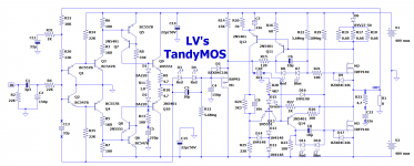
It has no diff-pair input, no DC-servo (yet its DC offset is negligible), no complementary output, no adjustments (yet its quiescent current is stable and deterministic), it uses ordinary vertical enhancement NMOS having a normal threshold voltage, yet it is free from the output swing limitations normally associated with such devices. The topology is half non-switching, half class AB and inverting.
In short: an oddity.
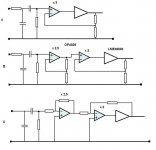
It is based on the Tandem topology, which has been evoked here: https://www.diyaudio.com/community/...here-is-the-legacy-thread.387391/post-7059293
I have already described a Tandem-based amplifier: https://www.diyaudio.com/community/threads/tandem-based-amplifiers.388400/post-7074596 but it was essentially a showcase and a test-bed for the concept: the VAS was simply an operational amplifier, thus limiting the power to 10~20W, since HV opamps like the LM143 have mostly disappeared.
It could certainly be used though, and for domestic applications the power is ample enough.
However, DIYaudio members prefer something more substantial, and here it is: the front-end is now completely discrete, meaning the rail voltages can be as high as necessary.

1663174531434.png


1663088218466.png


The tandem topology has been adapted to MOS (mostly by Minek), and a clever trick overcomes the limitation caused by the threshold voltages.
The Vth-erasers are simply voltage-memory circuits inserted in series with the gate, to reduce or cancel the threshold voltage, changing the MOS into a zero-threshold type. The circuits themselves are extremely simple: a capacitor paralleled with a shunt-regulating device (LEDs in this case), and fed by a large value resistor.
In principle, the concept could be used in any other amplifier (and I have done it in the Circlomos), but with "normal" amplifiers there is a difficulty: the voltage needs to be very stable and accurate because it will influence the quiescent current.
By contrast, the Tandem stage has its quiescent current tightly controlled by a feedback loop, and the only effect of a non-optimal voltage is a tiny reduction of the output swing: not a big deal.

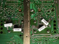
Unfortunately, MOS transistors do not shine in the tandem topology: with the original semi's line-up, I couldn't bring the THD below 0.85%, even with the tweaks at their optimum. M1 was a IRFD9120 (which explains the 4-pin socket).
With a BSP92 or even a BJT (2N5401), this was reduced to 0.25%.
Better, but a far cry from the BJT tandem: 0.004%.

The inferiority of the MOS version is probably down to the numerous parameter mismatches: a BJT is characterized by the BE PN junction, which becomes a NP junction for the correction transistor, and there is relatively little wiggle room outside of the fundamental exponential V-to-I relationship.
With MOS transistors of different sizes and polarirty, things become much more complicated. It is probably possible to improve the matters by hand-picking transistors having nicely scaled parameters, but I didn't go that far.
Anyway, in this case it does not matter very much, even with the worst-case 0.85%.

The front-end has a huge open-loop gain (almost half a million), and a relatively mediocre THD: between 1.5 and 2%. This THD will dominate, because there is no definite addition rule for THD: in theory, perfectly coherent distortions could add arithmetically, or anti-coherent distortions could even cancel one another (error-correction situation), but such situations only happen when they are deliberately planned for.
In normal cases, you are somewhere in-between. When lots of random processing blocks are cascaded, the end result will tend towards the root of the sum of squares, but in simpler cases, it could be anything but will generally be close to the largest value, in this case ~1.7%.
When the loop is closed, this value will be reduced by the loop-gain, which is substantial, and results in a final THD figure of ~3ppm, thus quite good, but not enough to qualify as a "super-amplifier".

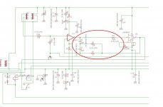
About the front-end:
It could raise eyebrows: it is based on a raw, undegenerated diamond structure, which looks risky and brutal. Howevever, because of the GNFB, Q3/Q4 and Q7/Q8 are forced to have the same current, and the rest of inequalities only have a minor effect.
In practice, it works like a charm: I picked the transistors at random from the drawer, didn't attempt any matching of any sort, yet it worked perfectly.

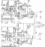
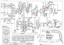
The schematic has oddities that deserve explanations:
C4 and C5 compensate the negative capacitance generated by M1.

The feedback network is split in two sections: R31/R32 and R30/R4. With a single network, the feedback resistor would need to be quite large if the input impedance has a civilized value, like 10K.
With a large resistor, stray capacitances can have unpredictable effects, which are neatly avoided here.

D15 generates a voltage transmitted by D16 to the "memory" circuit, precharging it.
In cold start conditions, with a large signal applied, M3 is unable to conduct sufficiently to satisfy the FB loop and M1 becomes saturated, leading to an overcurrent in D7 and D8 and the protection diode D9..
M3 is not controlled directly by the signal: it is slave to the upper transistor, via Q12, Q13 and Q14, and if M2 is off, M1 can conduct as much as wants it cannot make M3 conduct if the Vth eraser is not ready.
The precharge voltage is unsufficient to make M3 conduct, but it can as soon as an additional stimulus is added

This is the circuit with a BJT instead of M1: the Vth eraser has been shorted:

1663088452512.png


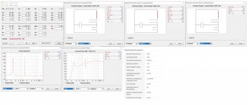
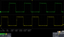
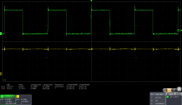
This is the 10kHz trangle response, just under the clipping:

1663088557258.png


The same, clipping:
1663088631596.png


Squarewave response, also 10kHz:

1663088709358.png


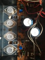
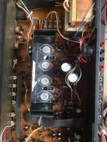
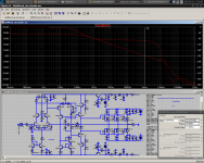
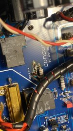
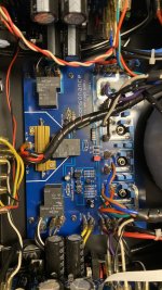
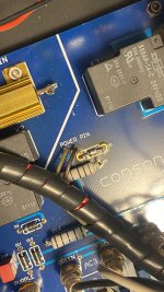
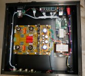
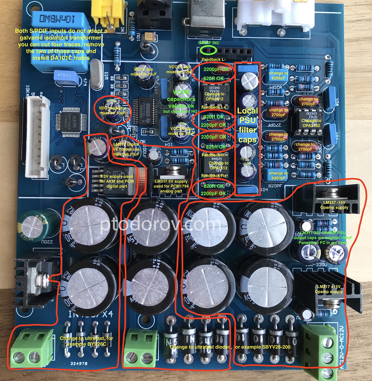
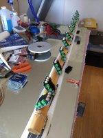
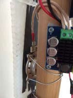
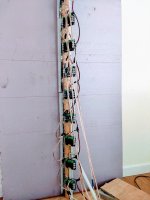
The measurements were made on this circuit:

1663088853979.png

I also include a simulation file, but it is not up to date: simulation and reality diverge significantly with this type of circuit

Attachments

  • Tand1.asc
    Tand1.asc
    13.6 KB · Views: 121
  • 1663149545960.png
    1663149545960.png
    35.6 KB · Views: 374
  • Like
Reactions: Junm

For Sale Neurochrome Differential Preamp, 8 x 2, with input selector board, all fully built.

Hello,
I'm presently unemployed and am clearing out my extra audio gear.

For sale is a fully built Neurochrome Differential Preamp. 4 stereo diff inputs, 1 stereo diff output. Tom calls this the 8x2. Included is the built input selector board. LEDs were purposely kept long in for the right enclosure which I never made. Haven't used it since about 2017 but it worked fine when put away for storage, so last I knew it worked perfectly.

I've been soldering professionally for 30 years so please have confidence that the build quality is good.

$250 plus shipping from 63025.

IMG_2917.png
  • Like
Reactions: mrjayviper

RA 930ax problem on Left channel voltages

Service manual here
https://www.vintageshifi.com/repertoire-pdf/pdf/telecharge.php?pdf=Rotel-RA-930AX-Service-Manual.pdf


Hello, I am repairing a rotel ra930ax amp. The core issue was the left channel not working.

When I acquired the amp, one of the rectification fuses F902 was blown, which was easily replaced. Someone had also bodged a 10A (!) fuse for the left channel, which I also promptly swapped out.

The left channel still didn't work. I then spotted a pcb scratch, which i bridged, and now the left channel worked. However, there was a distortion compared to Right.

None of the transistors seem obviously faulty. I checked voltages, and I find that there are some differences in the left vs right.

Key issue is that the base of q615 is +8.5volts (EXPECTED = +1.2v). The base of q 613 is +7V. (whereas it should be c -0.5v as per schematic). Oddly enough, when I disconnect the speaker, this +7 drops to +1.6 (still the wrong voltage).

The right side doesn’t have this issue, using exactly the same speaker and cables. Voltage at q614 stays stable irrespective of speaker presence.

I checked for other circuit scratches/ breaks and I cannot find any.

Bit stumped, any pointers would be greatly appreciated.

Goldmund Mods, Improvements, Stability

Hello everyone.

After the recent thread below, there has been interest in seeing how the circuit can be improved. This thread was created so that those not interested in changing the circuit can continue in the old thread.

http://www.diyaudio.com/forums/solid-state/174468-very-best-amplifier-i-have-ever-heard.html

This thread is to discuss improvements in performance, stability, and reliability.

Among the issues which were brought up:

1: The circuit can be unstable
2: Output stage bias has no clear adjustment
3: The topology can be improved
4: The frontend CCS is strange, it is hard to know what it was designed for. A more conventional CCS will be less confusing and more flexible.
5: Frontend rails may have sub-optimal power supply
6: Transistors used don't have adequate voltage specs for the rails

To start, I will offer my thoughts. These are not final, only to give you something to think about. I have attached several files. The first schematic is the original Goldmund amp. The second is the one containing the mods I describe here. The third attachment contains LTSpice simulations of them (where no models could be found for the original transistors, substitutions were attempted). These mods aren't my final word, I vomited them into the simulator at light speed, for lack of time. How to use the simulations: To change test frequency, change parameter "freq" - to change number of warm-up cycles, change parameter "dlycyc" - to change simulated number of cycles, change parameter "numcyc". When performing an FFT, select the same number of points as in the parameter "FFT". If the .MODEL statements are annoying, right-click them and select "invisible". They will reappear the next time you open the file.

Stability

Simulated, the frontend is actually VERY stable, showing textbook curves and well-defined behavior. The issues seem to lie in the output stage.

I'm never sure where to start when I consider designing an FET amp. Only special amps can drive hundreds of nF's of capacitance gracefully (the amplifier sees hundreds of nF if the capacitance is moved up to the driver stage as in an FET amp), plus there's a bunch of self-resonance and oscillation gotchas to watch out for. It must be hard for a simulator to accurately predict the behavior of a real FET amp.

The high degeneration on the differentials means very low phase distortion, which really helps stability when there is minimal compensation. That is, if you can account for the FETs' nonlinear capacitance. But I have no experience in this realm.

- keantoken

This circuit is also not unstable, barring any disastrous layout choices.

Open loop gain is a conservative 53db [according to simulation], with impressively well-defined HF behavior, thanks to the heavy degeneration. Phase margin is 75 degrees, which is not bad at all.

- keantoken

Jam, it is not unstable, I don't know why you would think that. Without the heavy (75 ohms!) degeneration on both LTPs it might be. See my post:

http://www.diyaudio.com/forums/soli...mplifier-i-have-ever-heard-9.html#post2328755

- keantoken

Hi Keantoken,

I agree that heavy degeneration of the diff. or VAS would help buy there are more factors at play here. We are not talking sims here as they are only a guide.

Question to be asked is how this heavy degeneration could affect the sound?

Regards,

Jam

Ok, I'm not an engineer and have no qualifications, and there's no reason for anyone to listen to me, but in simulation the circuit has very well-defined gain behavior. After billions of hours simulating, I am dead sure that this is almost solely because of the high degeneration resistors, which swamp nonlinear Gm and therefore linearize phase/pulse/HF response. Considering this, the frontend should be VERY stable, it's the power stage that is problematic. Am I right? Does this mean that the oscillation is more a problem with the FETs self-oscillating? It would take a very highly reactive network, like the high-Q stuff that comes from active components near oscillation, to throw the frontend off. Am I right?

- keantoken

Keantoken,

You are on the right track. My main problens were with the output stage. I have built the same amp with different layouts with some being stable and others not. All I am saying it test the board out first before releasing it.

Jam

Nagys,

You are totally off base. Your assumption that if use the same parts the amp will be stable. Well, what about the board material, layout, component spacing and location and list goes on, after all we are talkingf about a high speed circuit here.

[...]

Jam

Output Stage Issues

Firstly, the output FETs have no emitter resistors. Since devices vary widely, and no equalizing force is present, the FETs probably won't share the load equally unless matched by hand.

Secondly, there are not trimmers included in the circuit for output stage adjustment, only one for offset adjustment. We do not know how - or if - the output stage was adjusted at the factory. Adding an adjustment for offset would go a long ways towards making the design more consistent and reliable between builds.

My suggested options for adjustment:

1: Use a trimmer for R20 first, and set bias to a reasonable value. Then turn off unit, measure trimmer and replace with a close value resistor.
2: Install a trimmer permanently, in such a way that a wiper disconnect will not destroy the output stage.

Topology Improvements

The general topology of the Goldmund amp has been seen many times over in the past. Many members of this forum have worked to refine it in their own time over the years, and I am sure many changes might be made.

While we may be tempted to go all-out, this would likely result in the amp being hardly recognizeable in the end. If this is so, why not simply create a whole new amplifier? In this light I would prefer to keep the design "close" to the original. After all, it is my observation that after a few powerful mods have been made, the leftover mods decrease in the ratio of performance gain to price. There is one thing that I suspect is important to the amp's sonic performance. I will copy a post I made:

Wait, I didn't see your last response Jam.

I stated in my last response my observations on the the effect of the degeneration on phase behavior. While they decrease open-loop gain, they linearize phase behavior, at least for the frontend [by swamping nonlinear Gm]. This leads me to think they would improve imaging and soundstage. How they affect other aspects of the sound, I am not sure (hell, I'm not sure of any of this though). Due to the lowered OLG, the distortions of the output stage will be emphasized. This may not seem to be a big problem if the 2SK1058/J49 give benign distortions. If the FET parasitic capacitances are too nonlinear, they may ruin the phase behavior when played loudly.

Of course, it may be more difficult to tell how this behavior will change after the crossover threshold is reached.

- keantoken

Secondly, there are two modifications to the VAS which increase performance dramatically.

The transistors of the second LTP don't see an equal Vce, and so aren't balanced, even if they have the same quiescent. Without the second LTP being balanced, the current mirror is more or less for show. MikeB's Symasym cascodes this transistor to ground, and this balances the LTP at no signal. However the best way is to make the Vce's match. In my schematic I do this be cascoding the left transistor to the right's collector. This decreases distortion by a factor of 10, to .003%!

The second mod is considered after seeing Early affect on the lower VAS's linearity. At hundreds of volts Vce variation, it is not a good current mirror. One more transistor helps with this by shielding the mirror from large voltage swings. This brings THD down by a fraction, to .0025%.

CCS

The CCS was made in an odd way. I am not sure whether the designers' concern was noise or temperature stability, but one transistor is turned upside-down and it's B-C junction used as a diode. The behavior of this configuration will depend a lot on the specific transistor used, the originals being the BC182B. The Zener used is a 6V type, and IIRC zeners around this area have the lowest temperature coefficient. If we flip the odd transistor back the "right" way, tempco is fairly low among CCS's, given the two transistors are thermally coupled. This is the way I recommend. The output impedance of this configuration is not very high. However, because the gain of the amp is so high, the voltage variation across it is very low. Because of this, the contribution of the CCS to the overall performance is swamped by larger issues in other parts of the circuit. I don't believe going beyond this will reap great benefits, as far as the numbers go.

Frontend Rails

The frontend rails are constructed using a voltage doubler taken from a 60VAC supply. This results in ~120V rails. OS has described this as a "trainwreck"

Transistor Safety

For the frontend, rails are nearly +-120V. This means that at max power/clipping a transistor may see near 240V. Our transistors should be rated higher than this.

An apt alternative to using high-voltage transistors is to cascode. This way we can use common, familiar parts. In my mod, the MPSA93/43 are replaced by the suitably spec'd MPSA92/42, and output drivers are cascoded.

*catches breath*

Okay, I'm ready.

- keantoken

Attachments

  • AMPL.SCHEMATIC GOLDMUND.GIF
    AMPL.SCHEMATIC GOLDMUND.GIF
    44.2 KB · Views: 7,851
  • Goldmund_Kmods1.png
    Goldmund_Kmods1.png
    132.7 KB · Views: 7,564
  • GoldMund_Sim_And_Kmods.zip
    GoldMund_Sim_And_Kmods.zip
    10.2 KB · Views: 1,230

Dynaudio X18 good cabinet and drivers lousy crossover?

Dear all here!

Having bought the Dynaudio Excite X18 some time ago, I was never really happy with them.
I could hear their strengths but also their weaknesses, especially in the treble range that to my ears sounded kinda weird.

Unable financially and practically to try different amplifiers I started to look at
the crossover network.

I already had seen some pictures of them and felt a bit disappointed.
Could it be that there was more to be had from better crossover components?

I know this is a difficult subject and some would protest changing anything to get them sound better to my ears and in my system.

So one day I opened the cabinet to look a the crossover and drew up the schematic.

What struck me most was the parallel capacitor to the midwoofer, a Bennic bipolar capacitor!
Having build several loudspeakers in my youth I thought this was a big no no.

In the house were already two sets of Clarity caps, ESA and CSA.
I had originally planned to only change the series cap to the tweeter but after discovering the bipolar parallel to the midwoofer I had to change that one also.

Understanding that these are build to a price and probable price associated amplifiers
I wonder how far I can take this till I reach the limit imposed by the drivers and cabinet themself.

So far I can say that the most remarkable change is them sounding more natural to me.
The treble stange ness is gone and a lot more leading edge definition came to many instruments even synthesizers and keyboards that I never heard before.

Now the question is did I change the frequency balance by going from the Bennic bipolar to the CC ESA capacitors with regards to the ESR being lower on the CC ESA and from the
Bennic polyprop to the CC CSA?

Any input will be highly appreciated!

Anyone make OPA828 - LME49600 combination

A combination of low offset /low input current OPA828 should keep DC offset on output < 1 mV without the need for a servo .
For a HP amp with a gain of around 5 , what would be the best :
A ) One non-inv OPA828 with gain of 5 and with LME49600 in feedback .
B ) Two non-inv OPA828's with lower gain each , last one with LME49600 in feedback.
C ) Two inverting OPA828's with lower gain each , last one with LME49600 in feedback. ( inverting reduces overshoot according to datasheet , but THD is the same).
Any pitfalls like freq compensation or whatever that is in the pic below with the simular OPA827 in agdr O2 booster?

Attachments

  • OPA828 + LME49600.JPG
    OPA828 + LME49600.JPG
    38.1 KB · Views: 1,081
  • agdr.JPG
    agdr.JPG
    87.2 KB · Views: 1,098

A simple PA line array

Hi DIYaudionics.

I'm planning a single small line array PA speaker with 8 Visaton FRS 8M drivers. Its for acoustic instruments and singer, no drums and bass on own system. The long slender shape of the array suggests, that I could squeeze a few more Hz (below the Fs of 125Hz) out of it with a quarterwave-ish design, TQWT, bass reflex, TL or a combination of all (?), thus avoiding a sub-woofer, which is hardly necessary for a guitar and a female voice. The aim is not super HiFi, but something "good" sounding for small venues. I know, hard to measure.
My problem is, that when I try to use Visatons own design-program BoxSim, it is not clear to me how I combine several drivers into one vented "outer enclosure". It seems as if every driver has its own (and thus to big) enclosure. Other simulators may confuse me similarly. The exercise here is only the bass response, not the many ways of coupling the drivers and spikes and combs and whatnot. That is a different story.
When combining drivers in a common enclosure, I suppose the effective piston area is the combined cone areas when they work in phase, but what about the rest of the T/S-parameters?
I would greatly appreciate some opinions from the learned - and friendly - users of DIYaudio. I will of course document the result here with (simple, with Frequency Response Plotter 1.12a) measuments of the characteristics and the "Goodness" of the sound. How do I simulate the combined cones? Which (free-ware) program can you suggest?
Pitfalls? (yeah, lots!)

FRS 8M (11,5 Euros):
Z 8 Ohm
fs 125 Hz
Rdc 7.2 Ohm
Qms 3.24
Qes 0.58
Qts 0.49
Vas 1.1 l
Sd 29 cm²
Mms 1.8 g
L 0.3 mH

Entrepreneur wanted for speaker parts

There are a lot of speaker parts that belonged to John Busch in a storage shed in Kerrville, TX. They need to find a home and John's family isn't in that area to take on the task of selling them piece by piece.

This is a chance to buy a large lot of speaker building parts for pennies on the dollar and resell them for market value.

Likely perfect for a college student or retiree.

https://www.diyaudio.com/community/threads/the-john-busch-estate-drivers-speakers-amps-parts.388084/

Contact Pano at diyaudio.com

Thanks for looking!
  • Like
Reactions: Grarea

Belt Drive Turntables/Record Players with 2- or 3-Pulley drive System - Overview wanted

By accident I discover on the web this 3-pulley belt drive turntable - a good approach to avoid a general disadvantage of belt drive turntables:

Funk Vector Link Turntable:
https://www.enjoythemusic.com/superioraudio/equipment/0808/funk_vector_link.htm
under
https://web.archive.org/web/20080216232158/http://www.thefunkfirm.co.uk/V_Link.htm
I read this:
The VECTOR is the ultimate solution to the problem of motor pull. It is a 3-pullley drive system that is fed by an ironless rotor (low mass to you and me) DC motor that is mounted on the sub-chassis with the belt tension force then distributed about the sub-platter via 2 passively driven slave pulleys. These patented innovations are unique to Funk.

A similar approach was realized by an other brand which I have seen several years ago (maybe VPI industries - but I am not sure) - but the slave pulleys at this belt drive device are located outside from the platter.

check out more images (Linn SONDEK LP-12 mod to a 3-pulley drive system) in post 160 under
https://www.diyaudio.com/community/threads/linn-sondek-diy-mods-that-work.272570/page-8

more URLs:
https://www.hifinext.com/acoustic-signature-unveils-new-generation-of-neo-turntables/
https://www.stereophile.com/content/acoustic-signature-montana-neo-turntable
https://www.acoustic-signature.com/products/turntables/invictus-neo/

Thank you for calling more turntable brands/models with a three pulley belt drive system.

P.S.: from this approaches I'm less convinced because the pulleys aren't surrounded (distributed around the platter):
https://www.music-hall-shop.de/produkt/music-hall-mmf-11-3-plattenspieler/
https://www.stereophile.com/content...venger-reference-turntable-vpi-fatboy-tonearm
https://www.stereophile.com/content...n-acoustics-codia-acoustic-design-stein-music (fourth picture)
https://www.analogplanet.com/content/tw-acustic-introduces-triple-motor-module-raven-ac-turntable
https://www.pressreader.com/germany/stereoplay/20191004/281651076833538
even not from this approach:
https://www.diyaudio.com/community/threads/idler-wheel-magic.214019/

Attachments

  • acoustic-signature-hurricane-neo-motor-plst-01-1500.jpg
    acoustic-signature-hurricane-neo-motor-plst-01-1500.jpg
    102.3 KB · Views: 149
  • 16931-beed275d83055674cac448fc493c5afa.jpg
    16931-beed275d83055674cac448fc493c5afa.jpg
    46.2 KB · Views: 132
  • 1221turn.spindel.jpg
    1221turn.spindel.jpg
    39 KB · Views: 125
  • top-avc-automatic-vibration-control-01-1500.jpg
    top-avc-automatic-vibration-control-01-1500.jpg
    109 KB · Views: 134
  • vector_3_motor.jpg
    vector_3_motor.jpg
    20.4 KB · Views: 128

Voigt believer?

Hey all, put 2 different 3.5 drivers in small home built cabinets. Voigt is so easy to build and modifiable. The driver and port are so far away it seems? To open up the sound stage alot. Real airy. I am sampling with a good 2 way monitor and at close field I always like the single driver Voight cabinet. Maybe prejudice but with out any xover or phase issues the drivers just give their all? Michael

A tip for PCB connectors

Hi all
Problem ... I want to eliminate the hateful wirewrap wiring in an electronics of the 70s by replacing them with connectors that are more congenial to me but above all more practical, there is enough space to change them with something else so my attention has focused on two models that I have at home and with the same pitch (5mm.) to what I will replace.

The wire wrap connections have been placed everywhere in the electronics that I have on hand but it is in the preamp section that is from the tone controls board to the RIAA equalization to the line section that I am in doubt ... for all the rest I have already done and replaced but for now not wanting to influence the recommendations I will not indicate what my choice fell on ... the cables to be connected are 24 AWG.

Solution ... I have 2 types of terminal blocks

like this vertical and if it is the case also at 90 °

This....

DSCN6693.JPG


or like this JST-XH that allows you to remove faster the connections in case of assistance

DSCN6694.JPG


for the Jst-Xh I should only cut the "even" feet to insert them in the pcb due to the 5mm spacing. instead of 2.50 but that's not a problem, it cuts easily.

Which of the two would you choose and why? Advantages and advantages?

Belt drive Turntables using sliding Motor Base Unit - which Models ?

Record Player/Turntable Models wanted with Possibility of Varying the Distance from Platter to the Belt Drive Motor

I remember a turntable where there was an adjustment option for exact defining the right distance between belt drive motor and the platter. Very similar to those construction:
https://www.audiomatica.com/wp/?page_id=3024
Unfortunately I don't know the associated brand and model.

The aim for this could have been to compensate for different sizes and flexibility of various replacement belts, but also to adjust in exact manner the optimal belt tension.

From my view the right value for tension of belt is reached, when both the value for "Wow and Flatter" and current flow from the belt drive motor control is as low as possible.

However, there may be other aspects that must be taken into account concerning belt tension.

Maybe the adjustment instructions explain that in the associated service manuals of this models in detail, that I would like to know.
Thank you for an advice.

This thread is of interest in this case, but it is not only closed - unfortunately also deleted (dead link):
https://www.diyaudio.com/community/threads/belt-drive-turntables-a-lesson-in-physics.358391
This threads don't provide the right hints therefore:
https://www.feedandgrain.com/magazine/belt-speed
https://www.basisaudio.com/revolution-belt
https://www.vinylengine.com/turntable_forum/viewtopic.php?t=94218
https://www.theabsolutesound.com/ar...scendence-turntable-and-superarm-125-tonearm/
https://galibierdesign.com/support/drive-calibration/
https://www.vinylengine.com/turntable_forum/viewtopic.php?t=5644
http://korfaudio.com/blog92
https://vacationvinyl.com/how-to-measure-a-turntable-belt/

Issue to find out the right Parameters of Belt both for DIY Belt-Drive Turntable and Replacement

If the old belt is present, which is to replace, this question does not arise. Otherwise this question arises.
The same situation occurs for a diy belt drive turntable resp. record player.

The steps for determine of belt length resp. circumference while operation are easy to perform:

1) the motor pulley and platter hub circumference at whole (without the belt installed) by tying a piece of thread around the belt’s path.
2) pinch (marking) of both ends of the thread and measuring its length.

But this is the length in stretched condition with a certain value of pretensioning force.
This value nobody don't know by no belt drive turntable model - so I guess.

The following question occurs at first glance:
How is to determine the correct belt circumference when it is not tensioned?
Nobody can answer the question exactly and it only comes up when the original belt is no longer available or haven't ever exist before.

For each belt drive record player/turntable there must actually exist only one ideal value for the pretensioning force resp. necessary degree of stretching. The degree of stretching itself is dependent of the compliance (large difference between rubber and polyurethane), additional probably from the kind of belt (e. g. flat or round) so as the belt size (thickness resp. diameter) and the surface finish.

So the real question is for finding the correct belt size as follow:
What is the correct value for the pretensioning force of belt (right contact pressure on motor pulley and platter)?

This value is dependent from the kind of drive motor so as from the wight of platter and the kind of bearing/spindle set-up.

Is this value to low, the unwanted effects (through elastic slippage) are clearly audible (due to the elasticity of the belt, elongation processes occur in the belt during rotation around the pulleys. These stretching processes are due to the increase (or decrease) in the belt tension at the transition from the slack side to the tight side (or vice versa) – the belt stretches according to the force acting on the pulley).

Is the value to high, this leads both to high bearing loads and to increases belt wear.

How do professional manufacturers (Linn REGA, Pro-Ject etc) determine this value ?
And how can the user this value determine correctly ?

Thank you for an advice.

some URLs (belt drive basics):
https://www.basisaudio.com/revolution-belt
https://www.brinkmann-audio.de/inhalt/en/technical/a_short_study_on_turntable_drives.pdf
https://www.diyaudio.com/community/threads/non-stretchable-t-t-drive-belt.385162/
https://www.tec-science.com/mechanical-power-transmission/belt-drive/maximum-belt-stress/
https://www.tec-science.com/mechani...elt-drive/power-transmission-of-a-belt-drive/
https://www.tec-science.com/mechanical-power-transmission/belt-drive/bearing-force/

P.S.:
where is this thread ?
https://www.diyaudio.com/community/threads/belt-drive-turntables-a-lesson-in-physics.358391
after try to open I get only this error message from diyaudio.com:
Oops! We ran into some problems. The requested thread could not be found.

Ebay parallel PCM1794 DAC any good

Hey guys,


Does anybody have any experience with these?


HiFi parallel PCM1794A decoder board DAC core board 24Bit 192kHz V2.0 version 831230325287 | eBay


There seems to be a couple of different variants the all look basically the same.


I would be working on the basis the opamps would require replacement, maybe some caps as well but otherwise they appear to be a fairly serviceable looking design for the price.

Soundstream Class D controller IC

I have a 2021 Soundstream AR1.4500D, 4.5kW Arachnid and I'm trying to get directly at the Class D driver (controller) IC input pin(s), bypassing all the preceding filters except the IC's input coupling capacitor(s), which I'll change. I need a single pole High Pass 0.1 Hz response.

I don't have a schematic of the small, vertical control(?) board. At the top left of the board, what looks suspiciously like a 14 pin Class D driver chip is an STMicro(?), marked STMZ3U748. It may be an old or proprietary device, because I can't find a data sheet at the STMicro website. It could also be my aging eyes.

I may have completely missed the boat and the Class D controller is something or somewhere else. Please don't tell me it's on the backside of the main board.

Does anyone have a link, a schematic of the board and/or a data sheet for the Class D controller device? Anything from that same or a similar Soundstream Class D amplifier series will be immensely helpful.

Thanks,

Ron
Projects by fanatics, for fanatics
Get answers and advice for everyone wanting to learn the art of audio.
Join the Community
508,441
Members
7,919,382
Messages

Filter

Forum Statistics

Threads
407,764
Messages
7,919,382
Members
508,441
Latest member
fantas