Quickie 8417 Tube amp Inrush and transformer vibrations

Hey all,

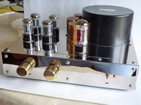
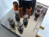
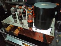
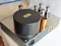
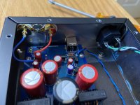
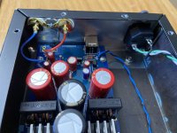
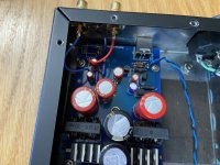
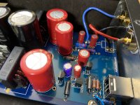
I have a pair of Quickie 8417 amps - the two rectifier version. It was returned and modded by Quicksilver for all other tubes (as said by previous owner), and currently fitted and biased for 6550 @ 70ma each pair.

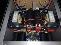
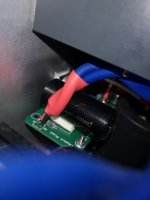
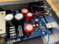
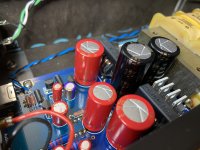
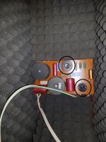
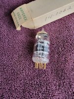
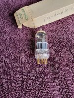
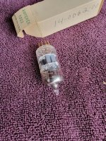
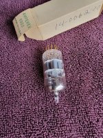
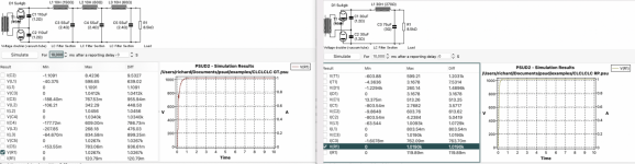
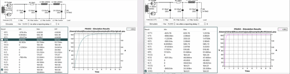
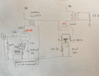
Anyway with that huge 390uf cap after the rectifier, I pulled the parallel pair of 5AR4 and dropped in one of my DIY SS rectifiers (an empty octal base with two series UF4007 from pin 6 to 8 and another pair of series UF4007 from pin 4 to 8, and base filled with hot wax). Don't really see an improvement in sound, but I just don't like seeing those expensive 5AR4s getting tortured...anyway, there is a rather hard and noisy start up from the power transformer...looking at putting in a CL60 or CL90 on tranny primaries...or better simpler option?

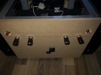
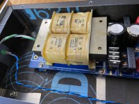
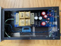
Also any advice for quieting the mechanical noise from Transformers? These two amp transformers have to be the noisiest I have ever had...

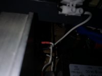
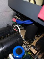
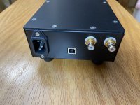
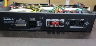
Also noticed it still does not have a Chassis ground...odd that the factory didn't bother adding it... I will add either way...

Leak Sandwich 600 project

I recently got around to fixing up a pair of Leak 600 speakers from the early ‘70’s. They had been sitting in storage for about 5 years, since I bought them, basically for the 12” sandwich woofers, which were ahead of their time. My brother had a pair in the 70’s and I was always impressed by the way they reproduced bass. Very tight and punchy for a moderate sized box (estimated 60 liters = 2 cu ft). My brother was a semi-pro drummer at the time, so he liked realistic bass. The mid-range and treble were nothing special and the way they were mounted side-by-side, stereo imaging was never their strong point. My plan was to replace the mid-range and tweeter with good modern equivalents and reconfigure the baffle to have mid-range and tweeter in a vertical line. I found that the 5” Peerless HDS P830860 drivers are a perfect fit for the existing cardboard tube mid enclosure. The old treble cut-out was blocked up flush and a new cut-out above the mid opening was made for a Vifa DT27TG-35-06. I know these drivers well and like their performance. The caps in the crossover were replaced just in case (they were over 40 years old!) and I tested the level matching with my Behringer RTA. The frequency response was flatter than with the original drivers, so no padding down of levels was necessary. Now I got a bit creative. The mid and tweeter sharing the same baffle as a 12” woofer is not an attractive idea. Usually this requires a really solid and braced baffle. In the original 2-way Leak sandwich speaker, the tweeter was mounted to the grille to isolate it from the woofer vibrations. Also the woofer magnet was tensioned up against the rear of the speaker by a treaded rod. Taken with the bituminous damped ½” plywood box, and the sandwich woofer, Leak were ahead of their time in many regards. However for the Leak 600 the threaded brace is dropped but a solid hardwood 2”x2” brace connects the baffle to the rear. In the spirit of the original idea, I wanted to partially isolate the mid and tweeter from the woofer by not mounting them to the same baffle. So glued a super-baffle with an enlarged woofer cut-out to the original chipboard baffle. The woofer mounts to the original (inside) baffle with the same mounting holes and the mid and tweeter mount to the super (outside) baffle. The two baffles are glued together by a 3 mm thick layer of adhesive damping compound (Bostik V60 glazing silicone). This is my attempt at a constrained layer damped baffle. The mounting screws for mid and tweeter do not penetrate into the inner baffle as this would provide a transmission path for unwanted woofer vibrations to affect the other drivers. The 3mm layer of silicone can be seen between the ply box and aluminium trim. New grille cloth and Velcro fixing complete the project. The level of vibration on the mid-tweeter baffle is noticeably less than on the rest of the box. I am ecstatic over the results. I consider that I have improved a flawed classic, while preserving the still excellent external cosmetic condition. The cheapo stands are modified IKEA Bekvam stools.
BEKVÄM Step stool - beech - IKEA
They are a perfect height but not they last word in rigidity. These speakers must be listened to on axis.

Attachments

  • DSCF1426.jpg
    DSCF1426.jpg
    614 KB · Views: 1,671
  • DSCF1446.jpg
    DSCF1446.jpg
    511.5 KB · Views: 1,516
  • DSCF1444.jpg
    DSCF1444.jpg
    474.6 KB · Views: 1,389
  • DSCF1439.jpg
    DSCF1439.jpg
    598.1 KB · Views: 1,663
  • DSCF1438.jpg
    DSCF1438.jpg
    541.1 KB · Views: 1,299
  • Like
Reactions: Freedom666

Kef Kube for 103/3 rebuild and psu

Hi All

So i received a pair of lovely 103.3 with the kef kube.

As you can imagine they need some servicing. Unfortunately the PSU has seen better days and would like to upgrade it, perhaps use a torodial or rcore transformer instead. The output voltage is 19.1vac at 230vac. This drops down to around 18.4vac when connected to the kube.

I would like to also upgrade the capacitors and opamps. Any suggestions for opamps?

Thanks


IMG_20190712_210951.jpg

IMG-20190712-WA0017.jpg

IMG_20190712_210958.jpg

IMG_20190716_180401.jpg

IMG_20190716_180421.jpg

IMG_20190717_221754.jpg

MOFO on Steroids

35x35x35cm big and 35kg of weight. Top materials and parts. Big mofo with 2,7A bias and regulated THEL AUDIO regulator power supply. The best I have heard and much better from any other psu in mofo. Big screw on KEMET capacitors. ClC psu befor reg. A truly hiend version of mofo and the sound is superb. I have build so many amps from pass, mirrand audio, hypex, symasym...... But the mofo with right preamp is the winner. The transparency is on another level. I have this in my system with Ccda 6sl7 preamp and this combo is amazing. Becose of weight I can shipp only with dpd, gls or dhl and the costs will be around 50 euro with insurance inside EU. The price for mofo would be 800 euro, or best offer.

Attachments

  • IMG_20221016_092309.jpg
    IMG_20221016_092309.jpg
    373.1 KB · Views: 380
  • IMG_20221016_092319.jpg
    IMG_20221016_092319.jpg
    385.5 KB · Views: 395
  • IMG_20221016_092324.jpg
    IMG_20221016_092324.jpg
    337.3 KB · Views: 378
  • IMG_20221016_092339.jpg
    IMG_20221016_092339.jpg
    114.2 KB · Views: 351
  • IMG_20221016_092415.jpg
    IMG_20221016_092415.jpg
    260 KB · Views: 347
  • IMG_20221016_092431.jpg
    IMG_20221016_092431.jpg
    196.7 KB · Views: 334
  • IMG_20221016_092437.jpg
    IMG_20221016_092437.jpg
    284 KB · Views: 367

Liberty Audiosuite configuration problem

I anyone out there still using Liberty Audiosuite? I've been getting great results from it for about twenty years. Last week, I moved my equipment around,
which involved disconnecting and reconnecting a few cables and I've now managed to lose the second calibration channel. So I can't do dual channel measurements any more - there's no signal on the bottom half of the screen. Single channel measurements work OK and I could probably live with that if it weren't for the fact that I've also lost the ability to do impedance measurements, which is critical (obviously).

So I guess it's likely to be a wiring problem, but I can't figure out what I've done wrong. I'm using the Echo card with the standard Liberty mic amp. Unfortunately, there's no drawing or photograph in the manual of how to connect the mic preamp and connection box up. I've checked all my cables for continuity and everything seems fine. I've also tried many different possible combinations of wiring but the second channel remains stubbornly unresponsive.

Any ideas? I have a backup Echo card, just in case.

By the way, this problem has forced me to look at some more modern testing software. I've tried Holmresponse, which I couldn't get to work at all, REW and Arta, neither are of which are very user-friendly. It might be because I'm used to it, but I'd still take Liberty Audiosuite over any of them. 🙂

  • Locked
For sale tubes line preamp AIKIDO topology.

The pre-amp has three golden-plated RCA line inputs through an ELNA gold-plated selector and two RCA outputs.

  • Four Philips JAN 6SN7 tubes, one SIEMENS GZ34 rectifier tube.
  • Gold-plated ceramic tube bases.
  • Jensen main rectifier electrolytic capacitor.
  • All audio signal caps are Clarity caps and Mundorf Mcap Silver oil.
  • All resistors are KIWAME and DALE.
  • The volume control is a ladder 24 DALE stepped attenuator.
  • Point-to-point construction.
  • Aluminum 2mm chassis electrostatic painting with copper nickel-plated cover in the front panel and above.
  • In general, is a HIEND preamp with the best components for all your life!
Price 2.000euros plus 50euros transportation cost in EUROP area.

Tasos Architektonidis
Athens, GREECE
demiurge30@yahoo.gr

Attachments

  • hdI-2h68.jpeg
    hdI-2h68.jpeg
    114 KB · Views: 195
  • PoGJJqUk.jpeg
    PoGJJqUk.jpeg
    138.4 KB · Views: 212
  • pre-aikido12-07.jpeg
    pre-aikido12-07.jpeg
    132.3 KB · Views: 190
  • pre-aikido12-19.jpeg
    pre-aikido12-19.jpeg
    145.9 KB · Views: 202
  • pre-aikido12-30.jpeg
    pre-aikido12-30.jpeg
    82.3 KB · Views: 197

Sonido SFR200A Open Baffle (with bass box)

I found the Sonido SFR200A speakers in stock at a local dealer. Since I have heard them some weeks ago at an audio show, I bought a pair. They are about the same price as a Fostex 206E but with a cast basket, wooden phase plug and AlNiCo magnet.

Before they get some proper boxes, I bought two 45 x 35 x 2 cm bamboo cutting boards. There is a 5 cm fold, so acoustically they are more like 45 * 40 cm. I routed the hole for the speaker and cut, glued and screwed on a piece of pine plank as the stand.

They are now running biamped with a Peavey FH-1 bass horn copy below ca 250 - 300 Hz. I can only compare them to my good old Beta12CX + Selenium D210Ti MLTL. I would say that the sensitivity is slightly lower on the Sonidos, but the sound is definitely better, it seems that it has even more treble extension. I need to confirm that by measurement, it may be also more like "presence" and not real HF extension. Also, the current test position is far from ideal, I need to test them further from the back wall with a matching bass cabinet below. Drums sound really amazing, the sound is very detailed, sharp and "fast".

I plan to build the Schalmei double horn with them as I do not want to stress the FR speaker below 100 Hz and have a proper low extension with a separate cabinet (most probably a small TH or Alphorn).

Attachments

  • front.jpg
    front.jpg
    133 KB · Views: 569
  • back.jpg
    back.jpg
    107.8 KB · Views: 559
  • Both.jpg
    Both.jpg
    116.3 KB · Views: 562

For Sale Two pairs of Sony VFET K82/J28+Two pairs of TOS:K2013/J313

For sale is almost the complete active devices needed to build DIY Sony VFET amp 2016(push-pull)
1) Two pairs of Sony VFET K82/J28
2) Two pairs of TOS K2013/J313.
3) Two pairs of C4793/A1837
4) One MQ of K170/J74 (Idss=7.7mA)
5) Eight pieces of TL431
You will need two pairs of irf240/9240 to complete the active device list.

Number written on the VFETs is Vgs tested according to the 4th picture.

price US$600 for the set, shipping inclusive.

payment by PayPal “Friends and Family”
please send me a PM if interested.

Attachments

  • CFB62BEB-C039-4CA2-A554-FC9B1EC39C73.jpeg
    CFB62BEB-C039-4CA2-A554-FC9B1EC39C73.jpeg
    332.3 KB · Views: 159
  • E3667AC7-AA8B-45C8-8D07-26F2D68A0432.jpeg
    E3667AC7-AA8B-45C8-8D07-26F2D68A0432.jpeg
    215 KB · Views: 150
  • 2FD0DA34-D6EC-4239-9F55-1DE03FECC58E.jpeg
    2FD0DA34-D6EC-4239-9F55-1DE03FECC58E.jpeg
    220.4 KB · Views: 159
  • DB1D728A-5883-4CC6-8878-D6B331853C4B.gif
    DB1D728A-5883-4CC6-8878-D6B331853C4B.gif
    51.9 KB · Views: 157
  • 66B1A957-9EE6-42E2-A09A-273C219BDD9B.jpeg
    66B1A957-9EE6-42E2-A09A-273C219BDD9B.jpeg
    706.8 KB · Views: 132

Blew up my denon PMA 2000 mk IV output transistors - advice needed

Hi y'all

While setting my bias current i blew up the two output transistors of the right channel of my denon pma 2000 mk IV :-(. Yes, I know, it's a stupid mistake...

I tested both transistors - Toshiba 2SK2967 mosf n channel - and they're shorted between source and gate/drain.
I'm looking for replacements, but I'm not really well informed on what to look for.

  • should I go for the same type or are there already better replacements? Are those from China on Ebay really the same, or are they copy's?
  • Are there other interesting platforms to buy on than Ebay? I know mouser, but these particular toshiba's are not available... I live in Belgium.
  • Do I preferably change all 4 transistors, so the left channel also?

- And, while the amp is completely on the table, are there other modifications that someone knows about that can improve sound? I know the preamp sections isn't the best...

I'm looking forward to your feedback!

Kind regards

Will

Volumio 3 help needed please

Hi folks. I am new to RPI and Volumio and have a 15 day trial of Premium. I have my library of AIFF files connected to RPI4 via a USB HD and they play fine. I can also play Amazon Prime Music through airplay. Using an IPad air4 as controller. The player App works great. Very fast response to track changes etc. I normally use upsampling and cannot get it to work. Enabling it and setting the Resampling to 88 or 176, 24 or 32 bits and saving the new settings does not seem to change the output. Both the DAC, a DDDaac 1794 with Wave IO board and the Volumio UI continue to indicate 44k, 16bit regardless of Resampling settings. What is disappointing is that I cannot seem to find any help on the Volumio forum. I understand that 3 is newish but I cannot establish if the Resampling feature is even working at this point in V 3 development. Some of this may be my fault for not being an experienced user but I don’t think I will be going forward with a subscription if I can’t sort this simple issue. I will then be looking for recommendations for other software to play my local ripped CD library, so if anyone here can help or has experience with other software to do the job please lend a hand here.

DIY speaker component extravaganza: RCA, Altec, Emilar, Renkus Heinz etc (part 1)

** PRICE REDUCED - 15% OFF LISTED PRICES ***

Hi,

Selling a boatload of surplus kit.

All items in Dublin and cash-on-collection most welcome, but happy to ship (preferably UK/EU) at buyer’s expense and risk. Payment via bank transfer or paypal friends/gift.

PM for further pics / details etc.

Cheers
Adrian

PS: Due to pic number limit (remaining items RCF RCF H3709 1” aluminium straight horn, Emilar EH 500 2” cast aluminium radial horns and single Emilar EE 1-2 1" ADAPTER, Renkus Heinz SSH820 2” cast aluminium horns, ZXPC 2" Throat Horn Bolt-On 18"x10"For Assorted Bolt On 2"Exit Drivers 90°x 40 and DDS CFD ENG 1-90 PRO-S 1” conical horns) in separate thread: https://www.diyaudio.com/community/...heinz-zxpc-and-dds-horns.389965/#post-7115311


(1) Pair of RCA 9458 3” phenolic/1.4” exit compression drivers with pair of NOS/uninstalled diaphragms.

These are RCA’s post-war, PM cinema compression drivers . Have the pepper-pot phase plug, I believe. On the right horn, supposedly good from circa 300 Hz to 6K. Plenty of info on the web.

This pair are UK badged and says made it in the UK, but I find that hard to believe. In excellent cosmetic condition (see pics).

Picked these up years ago (sans diapers) and managed to source 2 NOS diaphragms (in original boxes) since then. Measure 9.2 and 9.4 on my crap ohm-meter. Diapers have not been installed/used so new owner gets the very rare opportunity to hear these circa 70+ old drivers like new!

£2.2k.

IMG_2344.jpg


IMG_2345.jpg

IMG_2346.jpg

IMG_2347.jpg
IMG_2348.jpg
IMG_2352.jpg


(2) Renkus Heinz SSD 3301 3”/2”exit compression drivers (16 ohm) SOLD

Lots of info on web.

In excellent condition and measure 10 and 10.6 ohm.

Would make a nice pairing with the Emilar EH 500, Renkus SSH820 or ZXPC 2” horns I’m also selling (see below). Eg:

https://jelabs.blogspot.com/2018/02/altec-32a-32b-emilar-eh1210-eh800-eh500.html

https://www.diyaudio.com/community/...-home-system-pt-ii.330481/page-2#post-5811997

£150


IMG_2417.jpg

IMG_2418.jpg


(3) Single Altec 292a 2.88/3” phenolic/1.4” exit compression driver (16 ohm)

Picked this up years ago and had it remagged and installed with new 16 ohm diaphragm by GPA. Sat unused since then. Should be able to dig out GPA receipt.

In excellent condition and measures 10 ohms.

£300

IMG_2366.jpg

IMG_2367.jpg

IMG_2368.jpg


(4) Altec 23691/414 12” 8 ohm woofers (with 210607 cones)

These are “special” Altec 414s (b’s or c’s) which were used in its 1970’s Stonehenge I speakers. Both have the original 210607 stamped cones used for the 414 and the only difference that I can tell is the dustcap has no vent in the middle.

In excellent cosmetic and operational condition and measure 6 ohms. Happy to shoot through vids of working units.

£600

IMHO, would be an ideal match with the Altec 32c horns (see below) to whistle up an Altec version of the WE 753 ala JE. See: JE Labs: Altec 753C

IMG_2370.jpg

IMG_2371.jpg

IMG_2372.jpg

IMG_2373.jpg


(5) Altec 32c (plastic) 1” exit bent horns SOLD

Based on the WE 32a horn and used in various Altec speakers, including the A8, Model 15, A8, 9849, 1221/1231. General consensus is that this is the version to have (as Altec reworked the throat length to properly account for use with 1” drivers and is less resonant than earlier metal versions).

Loads of info on the net, including:
https://electravolt.blogspot.com/2018/10/the-tale-of-three-horns-variations-of.html

https://hifihaven.org/index.php?threads/altec-2-way-build-ala-jelabs-802-32-414.3452/

Becoming quite valuable now given the attention from J-Rob and JE.

In excellent cosmetic condition.

£400


IMG_2353.jpg

IMG_2354.jpg

IMG_2355.jpg

IMG_2356.jpg


/ENDS (PART 1)

Could I get some beginner woodworking advice please?

I am in the uk.

TLDR: I am trying to decide which way to go with tools.

I have used various tools in the past, but they are not very good.
But neither am I.
They were good enough for hacking up wood for garden stuff. Sheds, bases, fences, that sort of thing.

I have never had the time to work out how to do things better. Now is the time.

I do have a small garage, but I don't currently have a lot of floor space. Not quite big enough to fit an 8x4 sheet. But I am considering removing some stuff to make more floor space.
I am considering seeing if I might get rid of some things to make space. It all depends on how much space is required really.

I just got a second hand circular saw (i found my last one in a skip and I can tell why 🙂 ) But need to put more effort into making it square I think.
Bosch GKS 190. But I am not positive it is square.
I don't think my straight edge is straight 🙂

I have a half decent chop saw (bottom end makita).

I have started having a crack at the fun OB speakers to see where I need to improve.

My questions are a bit vague while I am trying to work out which way to go. If doing a half decent job will be too much money or space, I will have to accept it and try and find a place that cuts things to size.

I would like to be able to do it myself for other things like simple furniture as well.

Skill saw

My straight lines with a skill saw were not always straight. I am assuming that is my technique. Although, do better skill saws have better adjustments to get their angle dead right? Mine seems a bit vague when setting the bevel.
Also, is it actually possible to be as consistent with a circular saw as with a table saw?
I already know I need to make more space as I was over reaching, having to stand on it to cut it 🙂 stuff like that.

I also tried doing it on a folding workbench, but I think the floor is a better way to go while the bits are bigger, right?
I just need some thicker sacrificial bits underneath to allow for C Clamp space, right?
(Plus an actually straight, straight edge)

Table saw
I am thinking this is the other option.
I am also thinking I would love one.
I am also thinking I need loads of space for this.
Am I right I could roll the table saw under something for storage?
But then I also need support for the wood as I cut it, right?
I suppose the question is, how much space and money would I need?
(I think I might have to do some research into getting someone to do the cutting 🙂 )

Jigsaw.
Again, only had a cheap one which was frustrating to use.
I am thinking this is a necessary tool for driver holes.
Can I get some advice as to which way to go please?
what sort of numbers am I looking for?

I have an ok screw gun and corded drill.

Sorry it is a long one.
thanks.
  • Like
Reactions: easphyx

2-way with Ath CE360/Beyma CP380M and BR box/15" woofer

I plan on building @mabat's ce360 out of wood because I have access to cnc machines and I prefer horns/waveguides out of wood 🙂

My proposed crossover is at 800hz because the directivities would match with a 15" and ce360 plus cp380m can play that low and could still extend to highs. I think I will need to go for a bass reflex box to get some bass out of this setup. I like slots so most probably I will have the 15" in its own bass reflex box with slot on the lower front side and add the ce360 waveguide as a self standing unit on top.

I have access to B&C and Beyma 15" woofers. I think 40hz tuning could work with a suitable one . I am open to suggestions, I never played woofers up to 800hz, so I do not exactly know which ones to go for. Do lighter cones have an advantage?

I plan on doing it passive, a LR 24db filter would be ok, I guess.

Any suggestions, pointers or criticisms are welcome.

ps. I have rew and dats and will measure when I build the boxes and waveguides with the drivers to finalize the crossovers.

SE EL156 amp

schem.png

Hi

Im looking for some advice regarding an amp I´m planning to build. I have started to gather the components and at this point I´m looking for the coupling caps, 2uf 400V. They seem hard to find and the value 2uf is higher than what I´m used to. In amp´s I´ve built earlier the value is usually 0.22uf or 0,33uf.

So, my question is; is the value in the schematic 2uf right and if so where can I find a coupling cap with this value?

Any suggestions are helpful.

Cheers!

Arduino+PGA2311 Ultimate PreAmp with OLED and IO switching

It's finally finished. Nothing spectacular, but feature rich, pretty damn good sounding and fancy lookin'. Driven by a single, cheap 7.5-9V switching or linear power supply, with 5 inputs and 1 output with tape monitor , switched by small signal relays. Controlled by Apple TV compatible remote, panel operable with two independent encoders, with graphic 2.4" OLED. Attenuation done with PGA2311 running on +-5V with negative rail inverted from +5V and stabilized with -5V LDO. Firmware ported from LDR Pre MkII. Volume steps are 1dB, from 0-99dB

Why PGA2311? Because I heard Musical Fidelity M3Si which is using the similar chip for volume control, and it sounded fantastic.

All passives are SMD 1206, easy to solder even for 56 year olds like me.

Some of the features:

1. Sleep timer (1 - 255 minutes, 0 for disable). Also switches off external relay if connected, for turning off power amp for example.
2. Screen minimum brightness (0-255)
3. Screen maximum brightness (0-255). Screen dims down from max to min after Screen Saver timeout
4. Screen saver timeout
5. Channel Balance (+-20dB between channels)
6. Fully customizable input and output names
7. Fully customizable welcome message
8. Screen off time (1-255 minutes, 0 for disable)
9. Safe volume level - volume value will not be saved on power down above this value, to prevent a surprise on next power up.
10. Child lock - disable encoders and hide a remote 🙂
11. Automatic delayed power amp control, also manually switchable.

This has now been discontinued.
  • Like
Reactions: pbilous

Plate Amplifier Position

Looking some advice on whether its worth the extra volume to have a separate internal chamber for a plate amp.

I have a Powersoft Litemod 4HC (with heatsink) on the way as well as an 18 Sound 12LW1400 and am going to build something along the lines of 6th order bandpass enclosure that 18 Sound have on their website: 12” BANDPASS SUBWOOFER. 2 channels to power the sub in BTL and 2 channels to power a set of full range coaxial speakers i have.

A separate internal chamber within the sub for the plate amp seems more secure, but to provide adequate cooling its going to add a significant volume to the enclosure. Or is it likely to be fine in the main chamber. Keen to hear peoples experiences and recommendations.

Rion NL-52 Class 1 SPL meter + calibrator

Rion NL-52 Class 1 sound level meter in factory hard case.
UC-59 microphone (-27dB sensitivity).
Rion 512MB SD card.
NX-42EX software package installed (extended function program - logging, RS232 comms, comparator function).
Sold w/Pulsar 105 acoustic calibrator (Class 1).
Never field used - demo unit only - retained as backup instrument. Perfect condition.
Made in Japan.

Located in Melbourne, Australia. Will ship international.

Asking USD$2600 + shipping.

1660703281074.png
1660703306227.png
1660703400006.png

WTB AK4499eq

Hi

I have a multichannel D/A design based ob the AKM IC that runs nicely. However I need to extend the system and still habe everything exept the AKM. Maybe someone has one (or more!) still in stock and is willing to sell? I am ok paying a bit more than original price…
Btw: via ic Broker possible to get. But 4x the price is not worth it.

Thank you!

Transconductance mode (bufferless) hybrid BJT/FET class A amplifier codenamed Cicada

After a few months of modelling I came to this schematic. Like many class A amplifiers from 1970s and most of Nelson Pass designs it has no dedicated output buffer. The VAS/output stage works in a pure transconductance (current source) mode and its output impedance is maintained by the mean of NFB alone. It doesn't have a lot of a feedback so don't expect high damping factor, it's about 10 for 8 Ohm load. The input differential pair consists of highly degenerated hybrid JFET/BJT complementary pairs as I found this arrangement to be most linear. Also it allows to achieve a quite high bandwidth without causing any instability. So the primary gain stage and the source of non-linearity is the output totem-pole MOSFET arrangement. This arrangement was inspired by Yamaha B-1 in which the output stage is directly fed from the last of three LTPs which in its turn is powered from the separate negative rail. But in this case have I employed a folded cascode.
Also I decided to make an experiment and reduce output degeneration to the bare minimum just enough to make protection circuits work and use thermistor for quiescent current stabilisation.

MOS-A.png


Originally it was meant to have 20W of class A power but during prototyping I have reduced the bias to about 15 to lower the dissipation. Also it took multiple heating and cooling cycles to adjust the amount of thermal compensation. So it would be a good idea to use a some sort automatic biasing circuit.

A couple of photos of the prototype:
IMG_20220915_141626.jpeg

IMG_20220916_140610.jpeg


I would appreciate any feedback.
Eugene

Attachments

  • Like
Reactions: abstract and dkfan9

measuring the power choke inductance confusion

Hello, I bought the LCR hand meter (Escort 133A) and tried to measure my chokes inductance. I used a standard 100Hz frequency and on lundahl LL1638 20H/75mA choke I measured about 11H, Lundahl 10H/150mA choke - about 6H and other 20H/80mA choke has 14H. Thinking that something was wrong with a meter I tried another meter MOTECH 4080 with regulated measuring voltage. Changing form 250mV to 1V I got only minor inductance change.

Escort uses 0.6V for masuring. I tried also serial and parallel measuring method - same result. So, what's going on? Is it a problem with to low measuring voltage or a problem with large DC air gap, so some DC is needed to "start" a choke? Maybe a manufacturer is a bit to optimistic.

Anyone had similar experiences?

Maciek

SPDT line level switch on 12V trigger

Hi Everyone,

I'm hoping someone can help me find the right part. I'm looking for essentially a SPDT switch suitable for line-level audio that changes position when the 12V from a trigger source (like a HT processor) is on.

The idea is that I have an amp and I want it to switch from the 2-channel preamp to the HT processor when the HT turns on. When the trigger is off it should revert to the 2-channel preamp outputs. I have other things I am doing too, but this is basically it. Ideally solid state, zero impedance. I seem to remember at some point finding an ideal part via Mouser or Digikey but long ago lost to me.

In addition, would like it to draw as little current as possible when activated, and of course, this is line level audio so near zero current in the signal itself.

Thank you,

Erik

Bass boost for my computer speakers Dayton 12" DVC woofer

I want some better bass for my computer based music in the space under my desk.
I'm thinking about buying one of the Dayton SD315-8-8s and running it in dual 8R.
My wifes passive sub under her desk works like this as a .5 woofer boost but I need better bigger bass than she has. Ive been jealous ever since I made her the unit.
I can only find data as measured in parallel, before buying I am wondering if anybody has measured these in single 8R and if so by how much do the parameters change?
I can find room under my desk for a box 400 wide * 450 deep * 550 high so a closed box of around 90 litres internal and sealed, and naturally in a corner

For Sale Dale NH-100 4-ohm, 100W, Non-Inductive Power Resistors

Uncovered a bunch more Dale NH-100 4-ohm, 100W, non-inductive resistors. Theye are the aluminum housed, chassis mount ones that are great for dummy loads. I have at least a couple dozen. I also found the sainless steel 1/4-20 nuts for them.

These will ship from Carlsbad, California 92010. Asking $15 each, plus shipping. Local pick-up is also fine.

Dale-NH-100_001.JPG

Dale-NH-100_002.JPG
Dale-NH-100_003.JPG

Audiosector USB DAC for sale

I built this DAC several years ago. The circuit and the PCB were designed by Peter Daniel of Audiosector, and uses a non over sampling TDA1543 with highly optimized parts and power supply. There are a number of Blackgate capacitors in the unit, both the power supply and the audio section.

Like his gainclone amps, Peter has put great effort into the physical layout (small circuit paths) and parts selection for these units. I bought the PCBs with the chips (Peter mounted the surface mount chips for me, very helpful) and the transformer from Audiosector. I bought the balance of the parts from Michael Percy (Blackgates) and Digikey.

I built the unit using the parts specified by Peter on his schematic, including a number of Blackgate N (nonpolar) caps and Riken I/V resistors, some of which are now quite difficult to find as they are out of production. Despite a relatively simple circuit, this DAC has completely separate power supplies for the audio and digital circuits, and uses a total of four on-board power supply regulators. I had a custom faceplate made by FrontPanelExpress.

In good used cosmetic condition and excellent operating condition. Asking $350 plus shipping.

Attachments

  • IMG_5339.jpeg
    IMG_5339.jpeg
    474.2 KB · Views: 116
  • IMG_5341.jpeg
    IMG_5341.jpeg
    482.3 KB · Views: 103
  • IMG_5342.jpeg
    IMG_5342.jpeg
    478.8 KB · Views: 103
  • IMG_5343.jpeg
    IMG_5343.jpeg
    422.5 KB · Views: 111
  • IMG_5344.jpeg
    IMG_5344.jpeg
    480.7 KB · Views: 109
  • IMG_5345.jpeg
    IMG_5345.jpeg
    555.5 KB · Views: 105
  • IMG_5346.jpeg
    IMG_5346.jpeg
    378 KB · Views: 110
  • IMG_5347.jpeg
    IMG_5347.jpeg
    400 KB · Views: 96
  • IMG_5348.jpeg
    IMG_5348.jpeg
    424.8 KB · Views: 98
  • IMG_5349.jpeg
    IMG_5349.jpeg
    436 KB · Views: 103
  • IMG_5351.jpeg
    IMG_5351.jpeg
    421.9 KB · Views: 100

For Sale Big, F'ugly, Heavy Topaz 5kVA Ultra-Isolator Transformers

I have about 20 of these big Topaz 5kVA transformers. Most are still in storage, but these six beauties have been hanging around the house outside under an awning. I'm in no position to try and ship these puppies, so they are available for pickup in Carlsbad, CA. Asking $75 each ($100 - $25 ugliness adjustment 😉).
20221030_123758c.jpg

1966 Svetlana 6C4C NOS triodes - 6b4g equivalent

I have 10 of these directly heated russian old stock triodes available, and might keep 4: so 3 pairs for sale. I purchased them probably 20+ years ago, but have not done anything with them yet.

Shoot me PM if you are interested, and make me an offer. I do not know yet if they are of any value. Payment by USPS money order and shipping will be on you.

I have not tested them for characteristics, so, I’m not offering matched pairs at this point. Just wanted to check the market if they are of enough interest to try to offer matched pairs. In that case I will post individual photos and test data.

Attachments

  • image.jpg
    image.jpg
    354.3 KB · Views: 150
  • image.jpg
    image.jpg
    337.7 KB · Views: 134
  • image.jpg
    image.jpg
    298.9 KB · Views: 139

FREE: Big Electrolytic Cans 26000uF, 250VDC, 3" x 9", Kinda Heavy

Leftovers from an old project that never came to fruition. Mallory, United Chemi-Con, and probably others. Looks like over 100 left. Likely need re-formed by now. Bonanza for locals (Carlsbad, CA) -- free pickup. Shipping 'em is rather expensive. Two per USPS Medium Flat-Rate Box is $16.10.

20200613_141748.jpg


20200920_162514.jpg


IMG_0112.jpg

Cheers, -Casey

USB Audio - Asynchronous Mode - Explicit Feedback Implementation (on STM32, but interested more generally)

This is a bit of an open-ended question so apologies for being fairly vague.

I have an STM32F767ZI chip on a Nucleo-144 board. I want to use it to:
  1. Receive an audio stream from my computer via USB
  2. Do some processing on the audio e.g. mono sum and then some high/low pass filtering per channel
  3. Output to a DAC (in my case the TI PCM5102A)
I have an ultra basic implementation working which uses DMA to write directly to the SAI peripheral. This works for a few seconds, but of course because I am not doing anything clever yet, the USB clock is not synchronised with the clock used for the audio, so they fall out of sync periodically and this causes audible artefacts.

I understand from the USB specification (file here: https://www.usb.org/document-library/usb-20-specification, relevant material is in the main "usb_20.pdf" file, page 73 or section 5.12.4.2) that one "optimal" way to achieve this is to send feedback from the STM32 chip to the PC that sends the USB signal. Quoting from the spec:

"An asynchronous sink must provide explicit feedback to the host by indicating accurately what its desired
data rate (Ff) is, relative to the USB (micro)frame frequency. This allows the host to continuously adjust the
number of samples sent to the sink so that neither underflow or overflow of the data buffer occurs."

This makes sense, but I'm finding it really really hard to reverse engineer any of the projects that I've found that do this. A couple of examples I've found:
  1. https://github.com/ada-sound/X-CUBE-USB-AUDIO
  2. https://github.com/har-in-air/STM32F411_USB_AUDIO_DAC
The problem I have is that I can't run either of these projects because they're made for different boards, so reverse engineering by stepping through them with a debugger isn't possible. This makes it tough because I don't know C (a minor blocker which I'm working on!).

Another useful looking resource is this: https://www.st.com/resource/en/appl...mple-with-stm32f0-mcus-stmicroelectronics.pdf - "USB audio bridge example with STM32F0 MCUs". This looks like exactly the sort of thing I'm after, except there is seemingly no code example, and my STM32F7 has no 48MHz clock (as far as I can tell), and there's no mention of a CRS (the clock recovery system) in the datasheet.

Does anyone know of any resources that I can dig into that might give some more insight into this? I'm interested in application notes, code examples, forum threads, papers etc. regardless of whether they apply to STM32 - I think I need to try and absorb whatever I can get my hands on at the moment! Thanks in advance.

Possible to make a full range out of a full range woofer and a sub woofer?

Hi all,

I was wondering if it was possible to make a full range speaker with a smaller full range woofer to cover the upper bass, mids and treble (like a 4" or 5" full range driver) and then use a simple crossover to integrate a subwoofer driver (say an 8 inch) so that they blend with a little highpass and lowpass? I would think this would work but I never really see this. Maybe it's a bad idea and should just do a proper 3 way with a tweeter, mid driver and bass driver. For some reason I'm just fancying the idea of a simple full range driver, crossover with a sub driver in a tall tower cabinet. Was thinking of a tall skinny tower, say 6" face, 10" deep, 33" tall or similar to that to blend in with most furniture height and sitting levels. Internally the full range driver would have its own enclosure within the tower, ported and tuned to where it will peak and then roll off. The sub driver in its own enclosure in the tower too, also ported, goal of 30hz performance in room. I realize this is not a far stone's throw from just splitting the full range driver into a tweeter and mid woofer and increasing the crossover complexity to a three way. I was just trying to think of a fun simple 2 way design that is "full range" without having to build a transmission line or horn design.

Very best,

Recommended replacement for JVC HSW1101-01A Ribbon (Leaf) Tweeter?

So, what would be a good recommended replacement for the JVC HSW1101-01A Ribbon (Leaf) Tweeter?

I know that there are many similar-looking speakers sold thru the years, but I do know for sure about these being the JVC as I purchased them myself from a wholesale speaker company in Los Angeles in the 80s for a grand sum of $17 each!

These were in my original VMPS Super Towers kits from the mid-1980s.

The speakers originally came with Motorola Piezoelectric Supertweeters. After a few years, they were upgraded with these JVCs.

The crossover is at 15kHz

Recently, while playing music very loud, both JVC Supertweeters were sparking and smoky smelling. They still make sound, but I guess it's time for a replacement.

I'm probably looking for something with good power handling. With my most recent audiogram, I can barely hear above 12kHz anyway.

Would the Bohlender Graebener Neo3 PDR be a good choice?

We sit about 10-15 degrees below the mounting point of the super tweeter, and about 10-15 degrees from the horizontal axis as the speakers are toed in a bit. We sit about 17 feet from the speakers. Our listening positions don't change.

Jeil power 600

Hallo all,
I got this amp to check out. It had lots of dry joints. I see that the transformer has no secondary output, so no symmetrical amp. I suspect it has a cap on the output using single rails. Does anybody have any info and perhaps a circuit diagram. I have not tested it yet.
Much appreciated.

Attachments

  • IMG_20221030_172441.jpg
    IMG_20221030_172441.jpg
    331 KB · Views: 256
  • IMG_20221030_172452.jpg
    IMG_20221030_172452.jpg
    328.5 KB · Views: 277
  • IMG_20221030_172631.jpg
    IMG_20221030_172631.jpg
    344.6 KB · Views: 309

Will swapping outputs improve sound?

I have a post in Solid State about wanting to get the most out of my NAD M3 that is currently in need of repair, but my thread isn’t seeing any action, so I thought I’d ask a simpler question here. As im going through the repair I thought I’d try to improve on it. I’ve seen multiple times where people say that the 2SA1943 and 2SC5200 while good, aren’t the greatest. I’ve also seen where folks have said that the MJL1302 and MJL3281 are incredible devices.

If I were to simply pull out the 2SA1943 and 2SC5200 devices and swap them with the 1302/3281 devices would that give any audible improvement? The drivers are 2SC4793 and 2SA1837. Could I improve on those?

But to start off, I’d first like to know if by changing the outputs to the better devices would I be able to hear any improvement or a change even.

Thank you,
Dan

Optimal amp characteristics for Scott & planet10 speakers

Hi,

as soon as the new house will be finally finished (it is becoming an epopee), I will have a FHXL with MA11MS and a Silbury with MA10.3.
I would like what are the optimal choices for the amps to be connected to those speakers.

Are class D amps acceptable? It would be handy for everyday short listening.
Tube PP with EL84 or 6V6GT (Zout around 4 Ohm) is what I would use when I want to enjoy the music.
Tube SE project will be delayed to the end of the year, so not an option by now.

I would like to have designers reply, but also users' ones.

Thanks in advance,
Roberto

Ultra-CAT PPR Veneer Glue & Tools

Container has been opened but not used. I ended up using a different glue.

Ultra-CAT™ PPR Veneer Glue 5 lbs
https://www.veneersupplies.com/products/Ultra-CAT-PPR-Veneer-Glue.html

Veneer Glu Roller with 2 extra pads
https://www.veneersupplies.com/products/Veneer-Glue-Roller.html

Veneer Scraper Tool (not pictured)
https://www.veneersupplies.com/products/Veneer-Scraper-for-Backed-Veneers.html

$45 + Shipping

Attachments

  • DSCF2854.JPG
    DSCF2854.JPG
    262.1 KB · Views: 106
  • DSCF2855.JPG
    DSCF2855.JPG
    239 KB · Views: 111
  • DSCF2856.JPG
    DSCF2856.JPG
    289.4 KB · Views: 108

How to make a RCA output for subwoofer on Reisong A10

Hello
I need your help please, I bought my first tube amplifier the reisong A10

But there is not output rca signal to connect a subwoofer.
The tubes technologie is new for me...

Importants things I need:
-the output volume of the rca must vary in the same time of the speaker volume. This will make a 2.1 system.
-Important things is the stereo I don't want to make a bridge in the input signal....Respect the dual mono mode / stereo mode

Could you tell me if I'm right if do this please ? maybe some coupling capacitors must be introduce ? I don"t want to destroy somethings.

modify.jpg


I join you just a part "preamp stage" of the schematics of the amp I found on google

preamp stage .png


I hope you could help me please, I thank you 🙂

Capacitor to protect Tweeter in active speaker, cheap or quality?

I am building 4 way active speakers and am going to add approx 30 uF capacitor to protect the tweeter from low freq and DC current. Is quality important in this situation? I am using a high quality Scanspeak tweeter, so don't want to limit it, but on the other hand no point buying a quality cap if it wont make any difference in this scenario. It will be cutting off way below the active crossover point.

(2) Amprex CBS 6922 Vacuum Tubes -- NH USA --

UNTESTED

$75 shipped USA or best offer

Attachments

  • 20221018_142343.jpg
    20221018_142343.jpg
    825.8 KB · Views: 103
  • 20221018_142348.jpg
    20221018_142348.jpg
    858.9 KB · Views: 100
  • 20221018_142411.jpg
    20221018_142411.jpg
    905 KB · Views: 93
  • 20221018_142414.jpg
    20221018_142414.jpg
    950.5 KB · Views: 97
  • 20221018_142419.jpg
    20221018_142419.jpg
    962.4 KB · Views: 85
  • 20221018_142433.jpg
    20221018_142433.jpg
    847.5 KB · Views: 92
  • 20221018_142439.jpg
    20221018_142439.jpg
    858.6 KB · Views: 88
  • 20221018_142443.jpg
    20221018_142443.jpg
    818.5 KB · Views: 98
  • 20221018_142446.jpg
    20221018_142446.jpg
    866.6 KB · Views: 94
  • 20221018_142500.jpg
    20221018_142500.jpg
    814.4 KB · Views: 89
  • 20221018_142504.jpg
    20221018_142504.jpg
    812 KB · Views: 88
  • 20221018_142508.jpg
    20221018_142508.jpg
    861.7 KB · Views: 83
  • 20221018_142512.jpg
    20221018_142512.jpg
    846.8 KB · Views: 87
  • 20221018_142559.jpg
    20221018_142559.jpg
    913.1 KB · Views: 85
  • 20221018_142605.jpg
    20221018_142605.jpg
    1,003 KB · Views: 84
  • 20221018_142635.jpg
    20221018_142635.jpg
    918.8 KB · Views: 78
  • 20221018_142644.jpg
    20221018_142644.jpg
    848.6 KB · Views: 87
  • 20221018_142648.jpg
    20221018_142648.jpg
    849.8 KB · Views: 89

Interest for Final GB for F5X Power Amp

Over the years we have been asked many times for F5X PCB sets and matched devices.
We have declined every time because a set of boards without the case is no use.

One of the senior members here has expressed a willingness to supply the case for a limited batch to DIYers.
So we wish to know if there is still any interest before we make the necessary preparations.

It will be a last-time GB limited to 10 sets.
They will include matched FETs incl. regulator FETs, PCB set and fully machined case.
You should be looking at a total building cost (fully finished) for a stereo amp of around 3000€.

Please indicate any interest here.
There will be no guarantees if we go ahead, but we shall try our best to make it happen, some time in 2019.


Patrick

Yamaha A100 problem

Hi,
i've got an intermittent problem with a Yamaha a100 amp.
Here are some clues :

From time to time, the right channel stops working.
From time to time, the right channel comes back to life.
From time to time, before it stops working or before it comes back to life, a noise can clearly be heard (attached is a sample of it).
This noise comes and goes in a fade in/fade out way.
Volume doesn't affect anything (well except volume when the channel works of course).
Both speakers and phones are affected.

Any advice ?
I suppose a recap would solve it but i'd like your opinion.
Thanks ! Fred.

Attachments

Spdif coax input circuitry

Hello, considering jitter, noise, distortion, sonic signature etc.. which is the "best sounding" spdif coax input diy typology of circuit:

1) simple 75 ohm resistor (NON isolated) 😱
2) 1:1 pulse transformer plus resistor (isolated)🙄
3) pulse transformer plus resistor plus 74HCU04 with resistor feedback (isolated)😱
4) pulse transformer plus resistor plus fast comparator (AD8611 or AD8561) (isolated) :hbeat:
5) resistor plus 74HCU04 with resistor feedback (NON isolated)
6) resistor plus fast comparator (AD8611 or AD8561)(NON isolated)

all obviously including 10/100 nF capacitors

The coax cable is professional but 2 meters long
The source could be any common commercial digital CD or network players
Input will be CS8412/14 for sure.

Thanks

Sound Loss In One Channel Sony TA-F808ES & TA-F555esR

Hello

Thank you for such a great site.

I have 2 Amplifiers that are exhibiting the same problem

Sony TA-F808ES & TA-F555esR

After about 10 minutes of use the right channel cuts out on the esR & the left channel cuts out on the 808ES. It's random. Sometimes the amps will work for 10 or so minutes, then the sound becomes fuzzy and begins to deteriorate completely. I have pushed "source direct" on the esR and the sound comes back in both channels but heavily distorted. I have read before that Sony equipment has weak solder joints/traces

Any Thoughts?

Paul

Thanks To Michael Chua!

Thanks to Michael Chua for his Dove speaker design. I already had the DA175-8 and most of the XO components from earlier projects. They sound great! 3/4" plywood for the main box with a side-to-side oak brace and 1/2" felt lining. Front baffle is 3/4" solid cherry with a tung oil finish. Using a Magnavox 6BQ5 console amp is plenty loud for me.

Attachments

  • IMG_0499.jpg
    IMG_0499.jpg
    384.9 KB · Views: 161

flexible active volume control

Hi,


some time ago two nice variations of the classical baxandall volume control came up, see Handy Non Inverting Active Volume Control and Active volume control with balanced output using 2 op-amps . Common to both circuits is to gain in the noninverting stage, which makes life easier when you need a balanced or a noninverting unbalanced output.


Recently John Broskie published a "dual opamp phase splitter" circuit, Unity-Gain Phase Splitters , intended for bridging amplifiers. This splitter fits perfectly in a active volume control. The feedback network is completly between the noninverting and the invering output, so the noninverting stage is not additional loaded by the low input impedance of the inverting stage.


This means we have the option for a balanced output as well as high drive capability of the noninverting output, which may come in handy e.g. when direct interfacing to a crossfeed network of a following headphone amp.


Comments are welcome 🙂


Cheers Thomas

Attachments

  • FlexibleActiveVolumeControl.png
    FlexibleActiveVolumeControl.png
    51.1 KB · Views: 468

Building a low-dropout 5mA CCS

I'm building a high-ish current series regulator that, like many, requires a CCS between the unregulated supply and base of the pass transistor. To keep dissipation low, it's in my best interest to keep a low voltage drop across the pass transistor, which leaves little room for the CCS to operate. It's easy to make a great, high bandwidth CCS that drops 10V, but MOSFET cascodes are off the table when we only have 2-3V to work with.

My first stop was @Mark Johnson 's excellent thread on measuring transistors' Early voltage and saturation characteristics, and Gary Pimm's articles on measuring CCS performance. I tried to recreate Pimm's rig using an AP, and test some bits of sand I had lying around. I was particularly interested in seeing how bad the MJE340's capacitance would be, considering the high Early voltage would make for an otherwise excellent CCS.

Here's what the test rig looked like. The supply is a well filtered Mean Well 48V switcher. I inserted a Vbe multiplier with a large bypass cap between the bottom of the sense resistor and ground to allow for easy trimming of the voltage across the CCS being tested, and stepped the voltage from the collector to the bottom of the emitter resistor to 1.5V, 2.0V, 2.5V, and 3V. Here are the results. The analyzer/generator is an APx515.

IMG_20221024_131653.jpg


The data is attached. Sweeps were run from 60Hz to 80kHz. The low frequency limit was set to avoid cap charging issues, and avoid any issues with 60Hz noise coupling to the circuit. The test signal is 100mVRMS (i.e. a considerable portion of Vce!). When reading the 1.5V lines, do consider that the reference voltage of 1.8V will exceed Vce, but interestingly most devices continue to do their thing, and some do it better than others. Also note that the Y axis changes from graph to graph.

The 250R degeneration resistor is evening things out, but there's still some significant spread between the different parts. I was hopeful for the 2SC6144SG, but the high capacitance won it the title of biggest loser.

I'll need to pick up some ZTX parts to try, and would like to see how little voltage I need to get away with a cascode using Si diodes for bias. Perhaps some logic-level MOSFETs could work, too, if anyone has suggestions.

I'm also struggling to calculate the shunt capacitance-- could anyone point me in the right direction?

Attachments

  • 2SC2240.jpg
    2SC2240.jpg
    68.8 KB · Views: 178
  • 2SC6144SG.jpg
    2SC6144SG.jpg
    64.7 KB · Views: 170
  • BC337.jpg
    BC337.jpg
    66.8 KB · Views: 160
  • BC550.jpg
    BC550.jpg
    62.7 KB · Views: 152
  • KSC1845.jpg
    KSC1845.jpg
    68.6 KB · Views: 170
  • MJE340.jpg
    MJE340.jpg
    71.3 KB · Views: 162
  • MPSA18.jpg
    MPSA18.jpg
    66.2 KB · Views: 173
  • MPSA42.jpg
    MPSA42.jpg
    72.6 KB · Views: 178

Line-level Mute Delay, Express PCB Version

I need a delay mute circuit for the output of a 71a DHT preamp going into a solid state amplifier. Looking on the scope I see a +8V spike on power up, and a -17V spike on power down. To be expected.

I wanted to purchase a board from iamwhoiam, but he is unreachable, so i figured I'd build my own. Here is his fine thread. He cites his own references in the first paragraph
https://www.diyaudio.com/community/...level-audio-output-delay-retrofit-pcb.358940/

I figured I could simplify his schematic in the following ways:
  • I have 24V on hand, and already have 24V relays, so got rid of regulator
  • Change relay config to shunt to ground vs series connection
  • Figured since we're just shunting I can just use one double relay vs two individual relays. Am I right?
Questions:
  1. I already have this relay. Will it suffice?
  2. Since I'm using 24V I figured I needed R5 so as not to exceed the 20V gate to source of Q1. I was planning on using the 2N700. Is this a correct implementation?
I'm using ExpressPCB to make the schematic and make the boards, so will post the files so anyone can order. Not sure if that works outside the US. I'll also make a few extra in case anyone needs- just pay the raw board cost + shipping.

Attachments

  • delayboard3.jpg
    delayboard3.jpg
    98 KB · Views: 186

WTB Looking for SITs K2087 or anything you may have surplus to your needs

Hi guys,

I have been wanting to build an amp with a SIT for a few years but keep missing out on them when they pop up on the internet and as THF-51s are stupidly priced now, I am searching for a cheaper alternative like the K2087 which is the latest fad or something similar. Let me know what you have.

PM me would be best, thanks!

Cheers

Merlin New Book

Just received my very own copy of Merlin new book: "Designing Power Supplies for Tube Amplifiers".
I Got it form Lulu.com.
Have not had a chance to read it yet, but I am sure I am going to enjoy reading it and learn a lot. I do have his other two books.

I have three heroes now:

Rod Coleman, Merlin Blencowe, and Morgan Jones.

Art

GU-50 Triode Mode

I am thinking of using GU-50 in triode mode and have experimented a bit. G2 is connected to the anode through a 100 ohm resistor. G3 is connected to the cathode.
My experimentation has so far resulted in sparks inside the tubes and/or destruction of the resistor between G2 and the anode.

Here is a schematic with Vak = 335, Vgk = -40 and Ia = 80 mA: http://www.jogis-roehrenbude.de/Verstaerker/LS50.htm If I hook up a tube to my laboratory supply with the same operating point, sparks occur inside the tube. The heater is connected to ground.

Have I received a batch of faulty tubes or is there something that I don't understand?

Reconfiguring an existing Power Supply using PSUD2 - could use some second opinions :-)

Hello everyone,

I have a 211 amplifier (circuit included below) and I have determined the existing power supply configuration and I am considering changing the Power supply caps from electrolytic to Film Oil (ASC X386S) based on popular opinion. The electrolytic caps are 20 years old, and having some exchange with another DIYer he suggested that a single CLC sounds better than multiple in a row CLCLCLC like I currently have. Your thoughts welcome on the topic of PS design, I have attempted as a layman to use the PDUD2 software to predict the ripple and response. I am sort of unclear on the criterion for a good PS based upon the article by Rob here which seems to suggest the slope on start up is indicative to the behaviour in use?

What apart from the obvious reduce ripple and hit the right voltage are the criterion for using PSUD2 to compare the designs?

Hopefully not a too stupid question!

Thanks!

Attachments

  • Original Power Supply.png
    Original Power Supply.png
    1.6 MB · Views: 167
  • New PS design.png
    New PS design.png
    4.8 MB · Views: 180
  • 211 comparison.png
    211 comparison.png
    367.3 KB · Views: 171
  • 6c45 comparison.png
    6c45 comparison.png
    404.8 KB · Views: 155
  • 211 6C45 circuit.png
    211 6C45 circuit.png
    1.6 MB · Views: 191

18" sub driver recommendation

Hello!

Newbie here, forgive me if I'm duplicating thread topic.

Planning to build 4 * 18" sealed sub for my HT.

Did research for a week and all I found were projects and reviews of Dayton Audio.

In my experience the most popular product usually doesn't disappoint me. But still want to know what other options I can get.

What I want is simple, <150L sealed 18" sub. That's all. Of course my budget has limits but not very important.(not tight)

Living in japan, products' accessibility also doesn't really matter to me(all difficult, slow and expensive... eu, us, ... whatever)

Any slight information would be grateful.

Thanks!

ps. Clarification : Want to get recommendations of good product experience or information about other products that are popular to diy.
Projects by fanatics, for fanatics
Get answers and advice for everyone wanting to learn the art of audio.
Join the Community
507,624
Members
7,880,760
Messages

Filter

Forum Statistics

Threads
405,896
Messages
7,880,760
Members
507,624
Latest member
Neilonpoint