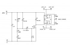
I need a delay mute circuit for the output of a 71a DHT preamp going into a solid state amplifier. Looking on the scope I see a +8V spike on power up, and a -17V spike on power down. To be expected.
I wanted to purchase a board from iamwhoiam, but he is unreachable, so i figured I'd build my own. Here is his fine thread. He cites his own references in the first paragraph
https://www.diyaudio.com/community/...level-audio-output-delay-retrofit-pcb.358940/
I figured I could simplify his schematic in the following ways:
- I have 24V on hand, and already have 24V relays, so got rid of regulator
- Change relay config to shunt to ground vs series connection
- Figured since we're just shunting I can just use one double relay vs two individual relays. Am I right?
- I already have this relay. Will it suffice?
- Since I'm using 24V I figured I needed R5 so as not to exceed the 20V gate to source of Q1. I was planning on using the 2N700. Is this a correct implementation?
Attachments
I think the link to iamwhoiam’s original circuit didn’t work above. Here it is again:
https://www.diyaudio.com/community/...level-audio-output-delay-retrofit-pcb.358940/
https://www.diyaudio.com/community/...level-audio-output-delay-retrofit-pcb.358940/
Check out this thread. If you are reasonably computer savvy (not much savvy needed, actually) you can program the chip to make this small board work. The code, the circuit, the pcb gerber is all there. If you are in the U.S. I can send you a programmed chip.
Very interesting! Looks like it takes care of turn off thump instantly as well? Turn off thump is actually much worse than onCheck out this thread. If you are reasonably computer savvy (not much savvy needed, actually) you can program the chip to make this small board work. The code, the circuit, the pcb gerber is all there. If you are in the U.S. I can send you a programmed chip.
Power supply voltage level is monitored continuously. Output is instantly shorted when the 08M2 chip detects that input voltage level has dropped to 75% of nominal. Nominal is the power voltage level measured about 10 seconds after power is applied to the pcb. The thinking is that by then surely the power supply has reached at, or very close to, final level.
I’m aware of that one but it’s too bigOr you could look at Pete's Board. Link to his eBay store is at bottom of the page.
Did you see this thread? Tom Engdahl's circuit would fit on a pretty tiny board . . . . .
Then again, how long from switching to spike on your scope? Could it be taken care of with an RC filter to a relay?
Then again, how long from switching to spike on your scope? Could it be taken care of with an RC filter to a relay?
Last edited:
No, it does not, it uses system power and starts to operate when the system is turned on.So does the unit need its own always on aux power supply?
The processor begins to operate immediately when power reaches it at 5V or above, and starts a timer that activates the relay after a 4 second (4000ms) delay (adjustable in millisecond steps if you want to edit the code).
The 470uF capacitor keeps the relay controller working after system power is turned off and the diode prevents the capacitor from discharging back to the power supply when power is lost. When voltage drops to 75% of normal, the processor activates the relay and the relay takes about 5ms to close. In effect, the relay closes within 5~10 ms of power dropping to 75% of normal and that should be well before any thumps develop. Because the capacitor between the relay and ground is fully charged, moving the relay to short the output signal actually requires the processor to short the relay to ground to discharge the capacitor. Thus, no power is required to move the relay 'cause the required power is stored in the relay capacitor waiting for the chip to pull it to ground through the relay.
Keep in mind that this is a processor-controlled circuit, don't be fooled by the low component count because it's smarter and more precise than a simple analog circuit and it can do things like wait for the power supply to stabilize before measuring what "normal" voltage level is supposed to be, and can calculate 75% of any normal voltage so it knows exactly when to short the relay when power supply voltage starts to drop. It will also recognize odd situations like when the manual "Mute" switch is already activated when you first turn on power and handle it accordingly.
Last edited:
Very nice circuit wapo. Can the time delay for startup be increased to 60 seconds (I assume so, but not sure what the max is)? I have the B+ already on a 45 second startup delay after the filaments.
I might take you up on the offer for some preprogrammed chips. Do you have any extra boards? Not sure what the cost to order just a few PCBs from gerbers are these days.
Although I am still have torn to just build my own circuit as in post 1, as it is also quite simple. Decisions, decisions.
I might take you up on the offer for some preprogrammed chips. Do you have any extra boards? Not sure what the cost to order just a few PCBs from gerbers are these days.
Although I am still have torn to just build my own circuit as in post 1, as it is also quite simple. Decisions, decisions.
- Home
- Source & Line
- Analog Line Level
- Line-level Mute Delay, Express PCB Version