What port diameter to choose

Hi,

I am planning on building a subwoofer box for my home theater with a digital designs dd506d2
The design will be a double reflex chamber tuned between 20-25hz with one chamber around 5 liters of volume and the other one around 20.

I have a question about what my port diameter should be:
I was thinking about 65mm the port will be 1 meter long this way (which is fine) and the air velocity at 100 watts will hit the 17m/s mark

A the moment i have a 8 inch infinity subwoofer with a port thats 50mm in diameter. This subwoofer has noticeable port noice/chuffing. So I dont know if a 65mm port will be big enough in diameter (the surface area of this 65mm port is almost double of the 50mm port)

Any comments would be highly appreciated

Modded RPi4 Board for better SQ?

Hello since i readed much about audio lately i wondered if it would make "sense" to mod a RPi4 board for "ultimate SQ" (kinda like the allo usb signature)

things i came across so far that do "in theory" make sense:

1. replace the DC/DC Converters, one step further would be to provide the different voltages directly but i think thats a step too far, and someone also posting here said good dc/dc converter do make nearly the same effect (maybe add filter capacitors too?)

2. filter capacitors for usb, maybe as a sort of decoupling for all usb devices drawing power?

3. remove the BT/WIFI modul or disable it in some way, since even if disabled in config it still actively transmits

4. replace the clock(s) for better ones

5. remove the headphone amp circuitry and maybe other unneeded stuff?

any other ideas/suggestions?

Tim Curtis pointed out in the moode forum (where i posted this thread too) that it may be a good idea to use the CM4 + I/O board, this would make it possible to buy the cm4 without wlan/bt to begin with and has emmc on board if wanted (and in the end it costs pretty much the same as a normal rpi4b+)

i wanna focus on usb playback and the i/o board seems to have a good layout, the pcie x1 could be used for a usb 3.0 board to drive a ssd and things like wlan/bt dongle (so the usb 2.0 can be used standalone for the dac, its also a good thing i think that the usb 2.0 chip is very close to the ports)
tho im not sure about the hat performace with this kind of board (official i/o board) since it has rather long lanes/traces

i also watched around for other boards (there are quite a few) but couldnt find any that looks better than the official one, most have just too much unnessacary stuff or too few usb ports... i specially checked those ones -> https://pipci.jeffgeerling.com/boards_cm (thanks for that jeff btw 🙂)

any ideas/tips are very welcome 🙂

Amplifer first few watt run at class A than class AB

While I was getting idea to use my 8 matched EL84 to a build a monoblock,
https://diyaudioprojects.com/Tubes/EL84-Mini-Block-Amps/
or something like a manely stringray clone

I was wondering how does commerical amplifer desgin their amplifer running the first few(8) Watt run at class A and run at class AB afterwards.
Is there any diy project or scheamtic I can refernce it to ? I am thinking to have the 4 nos of EL84 in push pull parallel runinng at class A in first 8 watts and run at class AB afterwards (maxium to 35W ?).

First Full Range Build... Any Last Minute Insight?

Hi all,

I've been wanting to try a full range tower speaker for a while. I'm used to building big cabinets and simple designs. But I've never had a full range speaker to work with. Figured I would start with that. I went through a few of the threads and one of the builds I saw struck my fancy, so figured I would start with something already known to work well and looks nice and uses affordable parts and isn't too complicated to build. I forget who's plan it was, but thank you to that person for sharing it, I shall try it I think!

Any last minute thoughts?

I picked up two Visaton BG20-8's for cheap and figured I'd start with this (I have these now).

Here's the plan I found in the other threads that was shared that I liked (thank you to the person that shared this, sorry I couldn't find a name I had saved this from a while ago, but want to be clear that I'm borrowing someone else's design here).

Is the voigt pipe more of a tapped horn or a type of transmission line? I'm confused with all the different types there are it seems.

I can't tell from the diagram, but is that 3/4th inch thick material or thinner? I'd like to use thicker 3/4th inch unless its not advised?

DDVP-20-01.jpg


Ultimately I will do a 2nd build, but it will be entirely from scratch using a smaller full range driver and a larger woofer for a WAF/FAST that I got interested in. However, I've yet to build crossovers yet, so again I wanted to start somewhere with full range without getting into that. I really like the idea of the simplicity of a single full range driver and a tower cabinet. So my first build will probably be the above drive and cabinet. It's not too complex for me to build and I like how it looks.

Goal for these full range towers will be classic 70's rock mostly.

Very best,
  • Like
Reactions: hmj

Help with impedance/TSP measurement in REW

I'm trying to measure TS parameters of drivers by myself.
I'm using these videos as guides:
Login to view embedded media Login to view embedded media
I have made the testing cable like instructed, checked it several times, resoldered the mic end a couple of times.
I have made successful measurements earlier with it, but now it just doesn't want to work anymore.
I usually had to restart my PC or switch sound cards (Realtek on Gigabyte x570 mobo or Asus Xonar d2x) to fix the problem and eventually I'd get it fixed, but not anymore.

I always get some type of this message with short circuit cal.
1643981881492.png


I have tried switching the channels, changing input and output volume in REW, changing bitrates (which somehow has also been a problem sometimes), switching sound cards, restarting, etc.
I had problems getting the open circuit calibration to work, but after a restart it seemed to work. Now I'm stuck on short circuit calibration, as I have been many times earlier and just given up...

Please help.
  • Like
Reactions: androxylo

Help me put these tubes into good use... I need a project

Hy,
I had recently acquired some parts from and old enthusiast...
Among the parts I got there are some tubes, most look new, unused in original packaging. Also there some retro looking pot knobs and such...

I would like to build something with them, search had revealed that those are mostly TV tubes, but also that they can be used for radio, preamp, amp,...

First of all I am aware that isolation transformer is a must, I had learned that the hard way, when I fryed all the ground traces on my pc motherboard.

TUBE LIST:
PL504
PCF801
PCF802
ECH84
PCL805
PCL86
PCC88

There is 1 piece of each, sadly no pairs...

And there was one that would need to be identified. It was in PCL84 box, but its writen ECH and B3B4 on it... filament needs 15v to glow and filament pins are 4 and 5.

So far I had just tryed filaments, all tubes have nice orange glow.

I already have EL84 amplifier that I had build few years back. It could use some preamplification, so I tought I could swap EL84 for PCL86.
This is the schematic:
EL84-AMP-2trafo.png
What would need to be done except of rising filament voltage to use PCL86 and benefit some gain?

Deciding if I will modify this amp would be the first step so we can know if I will continue either with EL84 or PCL86 into the new project...

For new project I was thinking either preamplifier (I wont need it if I modify my amp), Fm radio if possible? Or even better some sort of ham radio... I always wanted tube ham radio and I possible I would build that.

I'm open to suggestions,
Thank you
  • Like
Reactions: TonyTecson

Audio Technica AT ART7/ART9 MC Cartridges

Title self explanatory..
Anyone have any experience with either of these cartridges?

I am contemplating buying one for one of my Souther arms. Given my ability to make arm wands with the appropriate mass if necessary either could be a good match.

I am currently running a Windfeld on one and a Royal N on the other as a point of reference. Also have run an Ebony H which worked very well, but is a bit laid back for my taste and doesn't have the bass capability of either of the aforementioned cartridges.

Mark Levinson 38S - mains voltage jumpers

Hi All,

got ML38S with Japanese voltage. I know it is switched by jumpers (apart from frequency detector). Apparently located underneath PCB, but it seems it is not possible to remove PCB without cutting XLR connectors, which are Switchcraft brand. I made full restoration of ML 27, ML23.5 but never had any 3x series on my bench. Is there any access to jumpers other then fully removing PCB, or if not - whether its possible to remove PB without cutting XLRs?


IMG_7939.JPGIMG_7940.JPG

Expired / Discontinued & fake popular chips for chipamps - summary list [ongoing]

Hi! Thought i'd share my notes as I go through available reliable chips for chipamps.

I'm looking into making several amplifiers from popular designs, adapted to current realities. Many popular chips are discontinued and suffer from fakes, so I wanted to summarize my experience and search as I go through the state of affairs in 2022 (almost 23). This list is being updated. My current interest is in application to class A or AB, class D is excluded from this list. My next project targets a headphone amplifier or follower, but this list is not primarliy targeted nor limited to headphones.

Although an engineer (software), I have no experience in circuits outside of small projects, and am very grateful for feedback from those more knowledgeable. My personal goals are broadly guided by a desire for small amount of parts, possibility for reusing / recycling and best bang for the buck. The core principles behind my approach rest on the scientific method, so I aim to base my statements on replicable objective research and/or authoritative sources such as manufacturer information.

TDA 2030 / TDA2030 . 14 W hi-fi audio amplifier. Obsolete, according to ST as well as all suppliers for original manufacturer.

Discontinued by original manufacturer. Multiple fakes on Asian online marketplaces. Several published articles, including discussion on this forum, about marks of recycled chips (clipped & resoldered legs/leads), remarkings, etc. A somewhat reputable Taiwanese manufacturer is UTC, such as sold by Reichelt / Germany. I do have my suspicions about how exactly reputable UTC is, because their website UniSonic Technologies/UTC, when checked on Dec 1 2022, has an active bottom signature copyright date of 2011 and no HTTPS certificate, which does make me wonder if any care is given to the reputation of the company.

Alternative:
Possible replacement, with caveats and multiple opinions, is the NTE1380. Careful analysis of the specs for the specific replacement chip is warranted, as voltages as well as pin-outs may vary.

I would presume that someone getting the cheap kits or 10 for $3 chip bundles should be ready for the standard precautions and monetary and time expenses (referred further to as SP&E) before they use the Asian-sourced chips, with estimated expenses in the $30(50) to $100 range:
  • Getting a reliable multimeter for testing,
  • Making a test rig for the IC
  • Getting an electronic component tester
  • Insuring a DC protection circuit is used to protect speakers / headphones
  • Getting at least 10 IC components and thoroughly testing them, including overload, to make sure at least some resemblance of adherence to spec is maintained.

LM3875 - Discontinued

Fakes abound. Same SP&E. Replaced by LM3886, that has two additional signals, mute function and a virtual ground pin, that have to be dealt with if substituting. Some would say penultimately popular gainclone chip?


Active as of Dec 1 2022
  • LM3886 ( Texas Instruments (TI) ). 1 Ch, 20-94V supply stereo Class-AB amplifier. Highly regarded by many in the diy community.
  • LM317 and varieties (TI).
  • LM383T (TI) 7W Audio Power Amplifier 5-to-20V (TI)
  • LM1875 (TI) 20-W Audio Power Amplifier.
  • TDA7297 (ST). 15 W + 15 W dual bridge amplifier, designed for TV and Portable Radio applications. Highly regarded by many in the diy community.
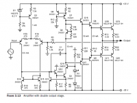
  • TDA7294 (ST) monolithic integrated circuit in Multiwatt15 package, intended for use as audio class AB amplifier in Hi-Fi field applications (Home Stereo, self powered loudspeakers, Topclass TV).


To be continued
Quick question, to confirm my reading of the rules- is posting links to manufacturer and spec sheets allowed?

New VRX928LA and XTI6002 sound upgrade for church

Hello All,

My church is currently upgrading their very old PA system to JBL vrx928la arrays. They will be flown, with 3 units on each L&R and Martin xp118 subs onstage. The 3 vrx928 will be powered by a Xti6002. I'm learning this as I go and am unsure about how to hook up the 3 vrx to the xti in bridge mode. Plus this is the first time for me working with Neutrik NL4. Any help you can provide will be greatly appreciated. I don't want to blow some $1600+ speakers. I want to be sure I hook them up correctly. This will be easy for a pro, but our congregation doesn't have such a person and they want to avoid hiring one if they can help it.

TIA,
Dan

The best Audio Books and Magazines about Loudspeaker (like Speakerbuilder) - Overview

about the German Forum
Theorien und Literatur über Lautsprecher - Verstärker, Lautsprecher, Zubehör - Analog-Forum
you will find a good overview.
here on diyaudio I have found only this:
DIY Loudspeaker Books - diyAudio
loudspeaker books - diyAudio
about
www.hornlautsprecher.de - solutions in sound
a lot of datasheets and the complete book (in German) "Dichtung und Wahrheit" you will find as PDF file

Magazines:
Voicecoil:
audioXpress | audioXpress Magazine. Advancing the Evolution of Audio Technology - Since 1970 - test example:
http://www.moreleurope.com/data/mediablocks/ST 728 Voicecoil reprint.pdf

More books and magazines (also from other countries) wanted - thank you for additional advices.

post #15 under
https://www.diyaudio.com/forums/everything-else/196492-recommended-books-2.html#post6749607
shows a very interesting book concerning horn constructions

Nakamichi PA7 - Issue

Hi everyone,

Thanks for reading - I hope this is the right spot to post this.

I have a Nakamichi PA7 and the power just flickered on and off a few times - and now it won’t turn on. It’s plugged into a surge bar.

I was wondering if anyone could shine some light on what could have happened to it, I would like to try and repair it myself if it’s doable.

Appreciate any input, hope you’re all having a good day.

Thanks

For Sale Audio Precision Sys-2322

For sale an Audio Precision SYS-2322 with additional USB interface. The unit can be used with Windows 10 and 11 in a Desktop or with a laptop and the PCM card (I was using it with Bootcamp in an iMac without any issues). The unit works perfectly and passes all the tests, it only has a small dent on the front which was there when I bought the unit. It has been used in a clean laboratory (not in production lines or the likes) and it is well taken care of.

The bundle includes:
  • SYS-2322 unit with CCIR2k, CC468-3, A-Weighting and 20kHz filters
  • APIB USB adaptor, www.s1usb.com (worth 290$ + shipping)
  • APIB PCM card with cable (cable not in the pictures)

The unit is in Hong Kong, asking for 3,800USD including shipping to anywhere in the world or a reasonable offer.

Thank you

Attachments

  • 20200617_113629.jpg
    20200617_113629.jpg
    310.3 KB · Views: 130
  • 20200909_145058.jpg
    20200909_145058.jpg
    427.4 KB · Views: 125
  • 20200909_145103.jpg
    20200909_145103.jpg
    317.7 KB · Views: 128
  • 20200909_145119.jpg
    20200909_145119.jpg
    242 KB · Views: 136
  • 20200909_145138.jpg
    20200909_145138.jpg
    288.9 KB · Views: 126
  • 20201222_195307.jpg
    20201222_195307.jpg
    138.4 KB · Views: 133
  • AP 2.png
    AP 2.png
    402.9 KB · Views: 125
  • AP 3.png
    AP 3.png
    384.8 KB · Views: 121
  • AP Screenshot.png
    AP Screenshot.png
    468.1 KB · Views: 130

BeoVox 1200: Passive to Active wireless Stereo Speaker set

Introduction
As an audio enthusiast, I like to use some creativity building speaker systems. But also using nice vintage audio products, upgrade them and extend their lifespan in a fun and useful way.

This time I took two speakers from the 60's: B&O BeoVox 1200. Traditionally built wooden casings, no top class but just nice speakers that fit well into many interiors because of acceptable size (W x H x D 50 x 20 x 24 cm) and nice natural wood looks.

Originally, these are passive speakers, so they would need an external amplifier. But in this case I transferred them into active speakers, each with its own amplifier, wireless + DAC module and power supply.

The setup I created looks like this:

Schermafbeelding 2022-11-25 om 10.20.58.png


Wireless transformation
The wireless magic has been added by using the products of Arylic: www.arylic.com

As I had PSU's and amplifier modules laying around, I choose to use Arylic's Up2Stream Mini module. Great module for this use, small and easy to install. The wireless antenna is easy to be put inside the casing of the BeoVox. The signal strenght is strong enough to do so. And it keeps the speaker in its original looks, with this 'invisible' antenna.

An alternative could be the Up2Stream Mono, which has a built-in mono amplifier.


Build

I took of the front grills and then removed the two speakers to create access to the inside of the casing. And put all components in place. Only for the Power socket, I created a square hole in the back side of the wooden casing, to put that in.


Conclusion
It is a great build and gives a lot of fun using these old vintage speakers, as if they are Sonos. The 4Stream App that comes with the Arylic products is great and easy to use. And has very similar functionality and ease of use as Sonos.

Money wise ... The speakers only cost me €25 for the set, the Up2Stream Mini 2x €49, and then a few Euro's for cabling, power socket and amp.

Hope this is inspiration to someone. Enjoy!
  • Like
Reactions: aagas and AllenB

Parallel noise filters/traps for mains.

Hello,
first of all i would like to make two statements
1) i am very ignorant on this subject
2) i feel the mains noise affects more digital equipment than analogue one. I listen only to digital sources so my interest.
I found this video on youtube:

Blue Circle Audio 6X Sillycone Optimum Effectiveness - YouTube

and this is the page on the Manufacturer site

http://www.bluecircle.com/page26.html

Very very impressive isn't it ?
I think that this device acts as a parallel filter or noise trap i do not know.
My question is ... where can i get a schematic for some filter/trap with similar effect ?
It is impressive and handy the fact the reduces also the noise from the power strip to which is connected.
Great product also the sniffer of course.
Thanks a lot and kind regards,
gino

Ignore functionality not working well

It was reported to me that ignored content was showing during certain posting operations.

On testing I was able to force the situation by simply linking to the post. Shown here, the content is already showing and so are the 'show' buttons.

Screenshot from 2022-02-22 23-11-16.png

(Random post and testing account)

* EDIT: Testing thread started here - https://www.diyaudio.com/community/...e-function-not-for-general-discussion.386750/

Markbass Little Mark Tube bias adjustment after repair

Hi there.
A friend brought me a Little Mark Tube for repair.

I've asked questions regarding the PSU there: https://www.diyaudio.com/forums/pow...ailure-ir21531-please-help-3.html#post6156903
But I was advised to start a new thread here since last question is not PSU related.

A faulty cabinet blew 2 output transistors and then the 2 power supply transistors. They were the 4 only parts I've diagnosed faulty and replaced.
The amp is working again 🙂
I've replaced the 6 output MOSFETs with Vgs matched trios.
Now...
Does bias has to be adjusted (via TRIM1 pot and if it's its purpose) and how?

There nothing explained in the service manual. Here it is: https://music-electronics-forum.com/attachment.php?attachmentid=37571&d=1453963798
The Little Mark Tube I have shares the same DA510 board. Schematic attached.
I've read on an italian forum that Markbass replied that idle current must be between 40mA and 50mA. But gave no procedure or values. That's all.

Any help would be appreciated 🙂
Thanks!

Attachments

  • da510 ampli.png
    da510 ampli.png
    72.9 KB · Views: 4,844

Best practice for voltage reduction of power transformer secondary...

Long-time listener, first-time caller!

I'm new to this world and only have built a few kits, this is my first build from a schematic and the learning curve is steep.

I'm curious to hear what is the best practice for reducing the voltage of a power transformer's secondary. I'm adapting a Japanese tube preamp design to accommodate US AC power. I've found an Edcor transformer that will put out 18VAC @ 3A - I will wire two 9V secondaries in series - however, the circuit wants 15VAC @ 1.5A. What is the best way to achieve this? A voltage divider? Diodes?

And best practices for reducing the amperage on this and the other secondary... resistors?

I'm sure there are a bunch of approaches and any input would be appreciated.

Thanks!

Mezzanine Power board for Raspberry Pi

I am using my Raspberry Pi as a network media player and cannot find a simple solution to feed my Raspberry and HAT DAC with quality power. Finally I made a simple board which can be used as HQ power source for both Raspberry Pi and HAT modules, and can be configured according your requirements.

Mezzanine Power Board can be installed between Raspberry Pi and HAT module and can provide up to 4 outputs to power PI, HAT and other devices which might require quality power source.

Module A – LT3086 Linear Regulator, 5.5VDC 2.1A, used as pre-regulator for Modules B/C/D/E, can be bypassed

Module B – TPS7A8300 low-noise, low-dropout voltage regulator (LDO) capable of sourcing a 5V 2A power for Raspberry Pi

Module C – LT3045 based ultralow noise, ultrahigh power supply ripple rejection (PSRR) low dropout voltage linear regulator can provide 5V 0.5A (1A for dual LT3045 C1+C2 installed) for HAT modules

Module D – LT3045 based ultralow noise, ultrahigh power supply ripple rejection (PSRR) low dropout voltage linear regulator can provide 3.3V 0.5A for HAT modules (or can be configured for any output 0-5V)

Module E – LT3045 based ultralow noise, ultrahigh power supply ripple rejection (PSRR) low dropout voltage linear regulator can provide 1.8V 0.5A (or can be configured for any output for 0 to 5VDC)
5V PI rail and 5V Hat rail can be connected together; in this case module B (or C1+C2) can be used to power both PI and HAT boards, same for 3.3V rail (by default it is connected, but if module D is installed and connected to HAT 3.3V rail, 3.3V PI rail is disconnected from HAT rail)

Below you can find some images for the "Light" version (only Module B installed) and "Full option" Board.

Attachments

  • PiPower-7905-WEB.jpg
    PiPower-7905-WEB.jpg
    543.7 KB · Views: 2,909
  • PiPower-7908-WEB.jpg
    PiPower-7908-WEB.jpg
    733.5 KB · Views: 2,840
  • PiPower-7909-WEB.jpg
    PiPower-7909-WEB.jpg
    461.5 KB · Views: 2,749
  • PiPower-7914-WEB.jpg
    PiPower-7914-WEB.jpg
    472.9 KB · Views: 2,735
  • PiPower-7919_WEB.jpg
    PiPower-7919_WEB.jpg
    732.6 KB · Views: 2,742
  • PiPower-7924-WEB.jpg
    PiPower-7924-WEB.jpg
    666 KB · Views: 994
  • PiPower-7932-web.jpg
    PiPower-7932-web.jpg
    696 KB · Views: 964

QUAD 405 transformer primary configurations

Hi, I own a first generation Quad 405 amp (s/n 49125) which does not have a voltage selector switch on the back panel as was provisioned on later models. To adapt to different world voltages, wires had to be desoldered and reconfigured. Quad published four diagrams that detailed the different configs for 110V, 120V, 230V and 240V. I'v searched online but can't find this diagram. Does anyone have the diagram that they can share?

Alternatively, can someone post a photo of their 405 transformer in this thread if it is configured for 120V?

Pictured is my current wiring config. There is a RED circle around a soldered connection between GREY and BLACK wires. I'm not sure the primary voltage configuration - it might be 230V or 120V.

IMG_4088.jpg

Rockford Fosgate punch 800 crossover distortion , no bias setting possible

Hello all!

I have a punch 800a2 which plays music but is slightly distorted.

With higher frequencies it gets more audible , on the scope there is crossover distortion. the same like turning the bias pot completely CCW.

The amp draws only 1 A and the current didnt get higher when turnin clockwise.

Usually if set correct, it will draw around 2-3 amps.

What can cause that no bias setting is possible?

Best regards!

The B.A.S.H

I have just completed a new speaker of my own design. It is based on the synergy horn concept, invented by Tom Danley. It is a 3-way design, built into a very large horn, loosely based on the Klipsch K-402 (but about 20% larger). It is somewhat comparable to the Danley SH-96, as it uses a similar driver arrangement. However, my design uses sealed bass drivers instead of ported, and I am using fully-active DSP crossovers instead of passive.

I have decided to call it the Big-*** Synergy Horn and will refer to it from here on as the BASH.

Here are some build photos:

IMG_1862.jpg
IMG_1903.jpg
IMG_1940.jpg

What potentiometer for IcePower 100AS2 (1.8k input impedance)

Hi guys,
Yes, I know there's a sticky about this topic, but no-one i've asked so far seems to be able to give a straight answer for a starting point due to the unusually low input impedance.
I'm populating some DIY stepped attentuators for going between my DSP and these boards, precision volume control is not a concern, think of it more as gain control so I can stamp out any noise floor from the DSP and set a safe max volume.

Can anyone suggest what value of pot I should be aiming for. From reading the sticky I'm thinking that 5k would be good, but I wanted to check with you smart fellas first.

No, I won't be adding input buffers or anything else, just passive volume control.

Thanks in advance!

To repair PSB subwoofer or not??

Hi, I have a set of PSB bookshelf speakers with subwoofer. The subwoofer is the Alpha Subzero1 (pictured).

584a8ce6-a045-450e-a453-558753d80865.jpg


The subwoofer is not working at all so I removed the power supply / amplifier board from the unit and discovered several destroyed components where the red oval is (pictured):

IMG_4051.jpg


IMG_4050.jpg

The components appear to be 1W resistor, a couple Tantalum capacitors and a couple of power diodes. The damage has extended to the PCB where a copper trace in that area of the board has lifted.

My question is whether or not I should try to repair this board or just abandon the idea and buy a new subwoofer? Thanks for your thoughts.

Questyle CMA800R Golden Class A Headphone Amplifier

Questyle CMA800R Golden Class A headphone amplifier in nice condition including original factory box and instruction manual. One of the top sounding HPAs. Well regarded with excellent reviews. The Golden version features a ceramic circuit board for low loss and better performance. Current drive operating mode.

$1195.00 plus shipping. Sells and ships to USA residents only.

Attachments

  • IMG_3977.JPG
    IMG_3977.JPG
    140.6 KB · Views: 60
  • IMG_3973.JPG
    IMG_3973.JPG
    134.6 KB · Views: 56

NAD 705 Not power ON

Hi Expert !

I am a novice. I have an old NAD 705 which works perfectly, until I cut the speaker wire...sorry...for the first time in 2 years...After that there is no more power, nothing. I check every fuse, everything is good. I notice that there is no current at the Swicth output, so I think it is the RL_301 relay that is blown... I force the relay to turn on by jumping it (see the red line in diagram) and NAD 705 powered on, YES! So I think it was the faulty relay, I change it with a new one and reinstall it...nothing changes...the relay does not close. I check the voltage at the relay, it was only 6 Volts, it needed 13v (see diagram below). So my question, why is it only 6 volts? This is beyond my competence. Anyone have a lead? Thanks in advance everyone.

Attachments

  • Capture.JPG
    Capture.JPG
    90.1 KB · Views: 125

Designing a Crossover for High End Speaker (Raal 70-20xr + Audiotechnology Flexunit and C-Quenze)

Designing a Crossover for High End Speaker (Raal 70-20xr + Audiotechnology Flexunit and C-Quenze)

Hi.
For the last couple of years, I have been making my ultimate speaker project. I, in my opinion, have gathered the best parts for that project, where i have been helped by Troels Gravesen and the makers of both Raal and AudioTechnology. I am pretty much done with my project.

However i hit one of the last hurdles on the way. The crossover. I have the measurement for my drivers, in my baffle, and wanted to design the crossover in xSim etc. My only problem is that im not experienced enough, to make the fullest of these wonderful parts. I've uploaded my beginnings of trying to make a crossover, but as you might be able to see, its a mess. I know i can make it better myself, but i wanted guidance first. My question to you guys is how i minimize the baffle refraction on the 18h52 and make the transitions smooth? - The cabinet is set, and is a homage to my uncle, it is already build. What im wondering is how you guys would do it, is there better ways to smooth out etc.

I hope some of you have some ideas or know where i can seek more guidance.

The speaker consist of the following parts:
Raal 70-20XR-NC
Audiotechnology C-Quenze 18H52 06 13 SDKAM-LR
Audiotechnology Flexunits 12 B 77 25 10 KAP

Best regards, Mads

Attachments

Tom Danley on human hearing and multiway loudspeaker defects

I think it is wise to post articles on how we hear (i.e., humans) vs. issues with multiway loudspeakers. Tom Danley of Danley Sound Labs (the maker of Synergy multiple entry horns) recently talks about the issues with having vertical or horizontal separation of drivers in a loudspeaker and how that interferes with the perception of stereo imaging:

Login to view embedded media
I recommend watching the entire 10 minute video to understand before commenting or asking questions.

Chris

Bass straight down to the floor like Tune Audio

Does anyone have experience with having the bass go directly into the floor so that the sound only comes out of a small crack. Tune audio uses that principle a lot. On their Anima, however, they have the bass at the top, with the sound only coming out just above the floor via the cabinet, which is a horn. I am considering trying something similar, however not with the bass at the top but with the bass just above the floor and then the cabinet upwards. It is only for the deep bass maybe max 200 Hz or less. It naturally provides some amplification, but it is also a nuanced and fast bass, it should not just be fullness and hum.

BiB ceiling speakers

Just wanted to get some opinions on the merit and implementation of this idea. I bought the 8" Yamaha ceiling speakers, but I don't like the idea of just slapping them in and covering with insulation. I was going to build a box within the joists for them, but having been playing around with the BiB calculator, I got to thinking, why not just build a BiB out of it since the speaker is intended as full range and I have an entire 10" joist making space above the ceiling for the box.

Plugged 80hz into the calc, it comes out PERFECT with a tapered box about 12"x16"x 8' long which puts my speakers in exactly the right position for the Dolby recommended placement, and the depth of the speaker is just shallow enough to allow the backpanel to just miss it. So it looks like this should be pretty simple:
  1. Cut a 4x8 sheet into about 16"x8' strips to fit between the joists.
  2. Install speakers in middle of chosen space between joists about 6' from either the front or rear beam (which places the speakers smack in the middle of my room).
  3. Place 16"x8' strips with tips glued to the back of the ceiling panel 20" from the speaker and glued to the top of the beam at the other end. I might need to add some height to the beams and joists at the wide end to make it 12" instead of 10".
  4. Cut a 12x16" opening for the port at either the front or rear edge of the ceiling with some sort of finishing for appearance sake. My wife, "So you're going to put huge holes in our ceiling that are open to the attic?" "No, just into the speaker box, duh." "So we'll still have huge holes in our ceiling?" "Well, yeah!" Lol, I'll probably cover them with something white and acoustically transparent.
So questions...
  • Is this a dumb idea, and should I simply slap them into the ceiling with a back box or just lay the insulation over the backs?
  • With speakers in the middle of my ceiling (a 5.1.2 atmos setup), would it be better to have the ports at the back or front? I was thinking back so that, although I don't have rear ceiling speakers, the opening would sorta simulate some bass coming from back there since the placement of extra speakers would be in that exact position in my room.
  • Should I tune lower than 80hz? I'm sure the 8" drivers could handle lower, especially with a BiB that enhances the low end, but my sub covers that well. Some sub bass from the ceiling might be nice, but it's not very directional and would probably require something longer than a panel cut from an 8' sheet, further complicating things.
  • Should I glue some sort of dampening to the back of the ceiling panels? Some ceiling acoustic treatment in the room would probably be good for my bare ceiling too, eh? I've never played with wall/ceiling speakers, but I've read that it's not ideal placement for them. Kinda hard to avoid that on the ceiling tho. Any tips there?
Edit: Looking at the specs, it says they have a "sealed back cover," but that's not exactly accurate...
1669833459378.png

bad DC noise down speakers only only when i first switch on

hello
so i replaced the main caps in my linn lk280, all seemed fine until next day i switch on speaker cones push right out ,loud noise. then when i turn off and unplug input cables it comes on fine all fine i can tap the input pins and all sounds correct, put inputs back in power up again and all is fine for long term use. Until next day exactly the same, please help 🙁( please note i leave the speakers connected all the time its as if some kind of dc charge has to dicipate first if i leave for an hour or so and switch back on its still fine ,if i leave over night WWWHHHOOOOMP!! speakers pushed right out and has to be on for a few mins with no input connected then its fine with the same inputs connected.

shane

CD player clock wire in Monarchy DIP

Interested in wiring a Monarchy DIP to a Magnavox CDP-460 CD player. The thought is to use the digital out of the CD player to the Monarchy. From the Monarchy back into the onboard DAC of the CD player. Has anyone ever done this? Is it a possibility?

The thought is to add a reclocker/dejittery thing in line without spending big bucks. Essentially like adding a tentlabs like item just outboard. I have a schematic for a Philips CD-160 which appears to be the same exact unit. Any thoughts would be welcome on how to accomplish this goal? Thanks in advance.

Hammond SEA Idle Currents

The Hammond catalogue here http://www.hammondmfg.com/pdf/5c0050.pdf gives a figure for "Maximum DC Bias". Does anyone know what this means?

Looking at the suggested tube applications, it would make some sense if this was a near-to-saturation peak current and the transformer was gapped for an optimum idle current of around half this value. When it comes to the 1638SEA, though, 45mA would not be optimum for an 845 or a 211 with a 10k load.

(I have tried asking Hammond about this, but technical questions are diverted to local sales staff who have no technical knowledge about the products they sell, and who are unable to find anyone in the Company who does.)

Amplifier with double output stage by Bob Cordell

Hello.
On page 68 of the book "A u d i o P o w e r A m p l i f i e r B a s i c s" by Bob Cordell there is a diagram
"Figure 3.13 Amplifier with double output stage". I tried to model it in lt-spice. That's how I described it (picked it up) and that's what I got. I got an order of magnitude more distortion. Did I do something wrong?
That was the first question. The second one will be next. So I made such improvements and got such a result. What do you think, colleagues, will this work in hardware in reality? I even made a psb for research in a hurry. Is there something that I didn't take into account, which is why my version of the amplifier may not work (I'm talking about both options, but of course I'm more interested in the second option).

Attachments

  • Cord_1_book.png
    Cord_1_book.png
    12.5 KB · Views: 884
  • Cord_1_my.png
    Cord_1_my.png
    20.6 KB · Views: 746
  • Cord_1_my_mod.png
    Cord_1_my_mod.png
    25.9 KB · Views: 771
  • Cord_1_my_mod_PCB.png
    Cord_1_my_mod_PCB.png
    94.2 KB · Views: 687
  • Cord_1_PH.png
    Cord_1_PH.png
    27.1 KB · Views: 564
  • Cord_mod_PH.png
    Cord_mod_PH.png
    26.7 KB · Views: 823
  • ааааа.png
    ааааа.png
    15.6 KB · Views: 906
  • Like
Reactions: pbilous

Set of 9 excellent UTC transformers, A-15, A-18, A-22, NE

Price lowered/Set of 9 excellent UTC transformers, A-15, A-18, A-22, NE

269,-eur

Price lowered

Up for sale set of 9 excellent UTC transformers :

SOLD 1. A-15 - 10/2.5K CT> 2K/0.5K - 2pcs, same series DP25
SOLD 2. A-18 - 15K CT > 80K CT

Sold! A-22 - 0.5K CT > 0.5K/0.125K - 2pcs, same series 7312
Sold! A-22 - 0.5K CT > 0.5K/0.125K - 2pcs
Sold! Northern Electric R20536A, Ind 0.323H/ 5:1

Nice condition.

Questions, info, pics on request, any time.

Transformers will be packed carefully with international tracking across all distance.
Sending from Ukraine. Payment by direct wire transfer.

FREE shipping to EU/UK.

----
See also other our items, we can mix all them together with our another items :

Grayhill 2, 3, 4 decks, single shaft rotary switches, up to 2x6, 1x12 poles

Grayhill 2 & 3 decks, dual shaft rotary switches, up to 12 poles

Canare L4-E6S pro audio cable 6mm, 4 wires 9 colors ~97m

Mogami W2944 pro audio cable, 2.5mm, 8 colors, ~236m

FS: Few different itmes - NEC relays, Meters, Caps, Cam, Cable

Attachments

  • DSC02883.jpg
    DSC02883.jpg
    499.8 KB · Views: 1,248
  • DSC02887.jpg
    DSC02887.jpg
    399.4 KB · Views: 1,149
  • DSC02898.jpg
    DSC02898.jpg
    469.2 KB · Views: 1,128
  • DSC02899.jpg
    DSC02899.jpg
    373.3 KB · Views: 1,142
  • DSC02900.jpg
    DSC02900.jpg
    349.8 KB · Views: 1,157
  • DSC02901.jpg
    DSC02901.jpg
    383.3 KB · Views: 414
  • DSC02902.jpg
    DSC02902.jpg
    291.3 KB · Views: 437

Classic Aleph Amplifier for Modern UMS Chassis - Group Buy

This is a group buy for circuit boards and MOSFETs to make a DIY Classic Aleph clone amplifier. This board set is designed to work with the diyAudio store UMS mounting pattern. The boards are flexible for making different Aleph variants, and power supply boards are also available.

You can see the main thread here: Classic Aleph Amplifier for Modern UMS Chassis

Group Buy #2 is now CLOSED.
Group Buy #2 closed 13 March 2022.
GB#2 Sign up sheet is here:
https://docs.google.com/spreadsheets/d/1w05jKUUwXxJUVIjuJXX3zeGQBRJD7ez2fiJqjWsOkS4/edit?usp=sharingLike Round #1 I'll reach out at the end to confirm order details, ask for email / name / shipping particulars.

GB#2 update 28 Feb 2022: I have purchased a bag of ZTX450's. There is a column to add those to your order in the GB#2 sheet to make life a little easier for folks. Stock is limited to 80 total. 2 needed per channel, 4 for a stereo pair. I'm not selling in bulk.

GB#2 Update 05 Mar 2022: I have matched a batch of FQP3P20. These are an alternative to IRF9610 for Q1-3. I'm adding these an option the sheet.

Post GB#2 Update - May 2022:
I have extra PCBs and MOSFETs available, please send a private message to me if interested. ZTX450's are gone.

Builder's thread is here:
https://www.diyaudio.com/community/...or-modern-ums-chassis-builders-thread.382316/

Attachments

  • Aleph 30+ Schematic Prototype V0.0d.jpg
    Aleph 30+ Schematic Prototype V0.0d.jpg
    962.2 KB · Views: 1,257
  • Aleph 30+ No Copper V0.0d.jpg
    Aleph 30+ No Copper V0.0d.jpg
    598.6 KB · Views: 1,028
  • Aleph 30+ Layout With Copper V0.0d.jpg
    Aleph 30+ Layout With Copper V0.0d.jpg
    693.4 KB · Views: 853
  • Aleph 30+ Layout No Copper V0.0d.JPG
    Aleph 30+ Layout No Copper V0.0d.JPG
    126.5 KB · Views: 912
  • Aleph Amp PCB-00a.JPG
    Aleph Amp PCB-00a.JPG
    146.9 KB · Views: 1,098
  • Classic Aleph for UMS-00a.pdf
    Classic Aleph for UMS-00a.pdf
    921.9 KB · Views: 549

LAMBDA Power Supply LPT-7202-FM

Greetings all.
I have a nice Lambda LPT-7202-FM power supply with some trouble. I have the service manual with the Part List, but all of the parts has a Lambda internal number. So I cannot replace the solid state parts like the integrate circuit that the number is FBT-031... I am looking for some chart able to give me the commercial part number.
Does anybody has this information that want share with me ?
Any help will be appreciate.
Best regards
Victor

Quad 405 parts refresh

Hello everyone,

I just got a Quad 405 that I want to refresh parts.

It is with the board ISS9 so I was wondering what are you guys replacing obsolete parts with ?

This is what I got so far.

1) All electrolytic capacitors were replaced by Nichicon 105C electrolytic.

2) Both 10000µF were replaced by Nichicon LKG1K103MKZ 80V instead of 63V to fit original size mounting ring (50WX80H) with soldering lugs like the originals.

3) Output transistors have already been replaced on one side, they are toshiba on both side but different year, I'd like to replace them with all the same version and year.

Original output transistor are 2SD424 and can be directly replaced by MJ15001 if I am not mistaken. If you have other suggestions, I'd be happy to see what you guys did.

4) Op map are missed match and one have been replaced (on the side where the output transistors have been replaced).

On the side that has already been repaired, the op amp is UA301ATC from 1977.

On the side that looks original, op amp is LM301AN from 1975.

I'd like to have both of these replaced but I have a hard time finding the right component. If you guys could tell me what you use on your 405s that are using the stock boards, I'd appreicated it !

Here are all the cross-reference I've found so far but not sure which one to pick at this point.

LM318, OP07, OPA134 and OPA277 all seem to match pinout but I am not sure about the rest of the specs.

5) The 40872 pre drive are originals from 1978. I think they can be direct replaced by TIP42C if I am not mistaken.

6) R30 and specially R31 have got a lot of heat, the circuit board has change color, I have redone soldering but the leads of R31 look oxidated. The value reading is spot on at 570ohms, they are 5% tolerance as the orignal schematic state for 10%. Not sure it is worth replacing them because of the heat stress they got...

Other than that, it's pretty much it. If you guys have any thoughts, I'd like to hear about it ! I tried to find information on the threads in here about the 405 but it seems many of you guys are having newer revisions and parts were not matching what I had here.

Again, I just want to refresh the components and that they be identical on both side and put the cover back on.

Thanks for all the input !

Attachments

  • 20210330_162633.jpg
    20210330_162633.jpg
    957 KB · Views: 654

RCA 5879 Phono Preamp

Does anyone have any experience with the 5879 phono preamp in the "RCA High-Fidelity Amplifier Circuits" booklet? The schematic is as follows.

5879 phono preamp.jpg


I have looked pretty extensively and only found a mention or 2 on the web, but nothing significant. I'm looking to build one as I have a bunch of the 5879 tubes and have used them in guitar and audio amps with good success. I have an entry level (at best) turntable with the Audio Technical AT-3600L cartridge, and I'm totally happy with the sound. That either makes me a noob or a philistine, or maybe both. Anyway, I proposed some changes as follows.

Phono-Preamp.jpg


1) Grid stoppers on all sections
2) 5879 screen bypass capacitor to cathode instead of ground
3) Instead of a 7025/12AX7, a 6AV6 and a 6C4 cathode follower (it'll be driving a 100k load). If the gain is too high, a 6AT6 can be swapped in.
4) Larger cathode bypass capacitors, because it's much cheaper in 2022

Also, how much of a difference would there be if I used a 22nF and 4.7nf caps for C5 and C6?

Any comments or insights will be greatly appreciated.

Ultra Slim Dual Down Firing Passive Subwoofers

Hi! Trying to build a bedroom system with dual (2pcs) sealed, passive, down-firing subwoofers. Main Speakers would be KEF LS50 so would need dual subwoofers to complement them and would need suggestions on drivers and any tips on the build.

GOALS: I don't listen loud in that room so 75 to 85 db max volume is okay, I just need the lower octaves fleshed out. As far as f3 is concerned I can be very happy to get stereo audible 40hz.

Crossover: Planning to crossover the Kefs at around 80hz since it's down firing so localisation shouldn't be that much of an issue. Ill be using a minidsp for this one.

Here's the challenge:
I can only build out these dimensions per sub woofer : Height 4" (4.5" with rubber feet) x Length: 20" x Depth 15"

Do guys have any recommendations on:
1. Low Profile Subwoofer for this use with a mounting depth of around 3+" ? Ideal budget would be 175$ for both drivers but the upper limit is 400$ for both drivers.

2. A cheap AVR that can drive the kefs and the subwoofer to around 85db.

This is a sealed subwoofer or so I'd like to imagine, any other suggestions on the cabinet build would be welcome.

Thanks in advance!

For Sale QA401 Audio Analyzer for Sale

Hello,

I am attempting to sell a QA401 Audio Analyzer by Quantasylum in nice and ultra-mint condition!
Since arrival, due to busy schedule, the QA401 here is used just for several times.
The QA401 I am selling is super new that I bout it directly from Matt in QA, every function is normal.

We are now in a severe semiconductor Crisis, and it seems it not going to relieve in a short time.
Many parts have incredibly long lead-time or prices.
So, I will just sell this out to invest other lab Test and Measure tools.

Send me a PM and We can discuss the price and shipment cost.

Regards,
Jen

Attachments

  • 20221024_012308257_iOS-1.jpg
    20221024_012308257_iOS-1.jpg
    383.9 KB · Views: 188

Amplifier for subwoofer

Hi folks, I figured I would pick your brains to see if someone has some ideas.
I've been thinking about adding a subwoofer to help the main speakers and add a little more bass (music mainly), but I'm unsure what route would be best.
My current amplifier has 2 (balanced) outputs from the DSP, but they are on two different DSP boards and can therefor not be summed there, so I need to sum Left and Right before the amplifier (if I would add two subwoofers later to eliminate room modes I would still want them to play the same).
I don't believe I need much power by the different subwoofers I've simulated, 200W seem to do it, if it's more then of course it's not a problem.
I might end up with a driver that has 4Ohm load, and accounting for a slight dipp bellow that is probably wise, so 3Ohm stable (?), but I guess I could find a driver that's more forgiving.
Is there any good options/solutions out there for DIY? Something that will make it as 'user friendly' as a plate amp that has two low level inputs.

Thank you in advance.
  • Like
Reactions: Ixnay

EV zlp 15" and elx 118p setup

Hello any advice would be greatly appriciated, i hVe just bought 2 elx118p subs and 2 ZLX15P tops. Can anyone tell me about the mic/line faderon the speaker do we put that quite high and the alter the master on the speaker? With regards to the subs do we setthem to around 120hz and on Boost for live show. We also use the allen and hearh wz3 16.2 s desk, so subs chained to mono and tops to left&right or from desk to top then link down ro sub each side. Any advice would be great thank you

Sony mic AC-2 for REW anybody tried it ?

Ok I searched this question has not been asked.
Im keen to get my REW system fired up and am on the look out for the bare min / cheapest calibrated mic.
I've given up on trying to build my own setup.
The two options Im looking are the Sony ECM-AC2 for 29$ on amazon.
The other option is the Dayton Audio iMM-6 for about 24$
I got all the parts to build my own. Like a 2 pin mic and some opamps. But calibrating sounds daunting.
But then on another post I was told to get a mic with phantom power, then to avoid USB.
My application is very simple freq res tests to see if the graphs supplied with drivers is accurate or not. And to get the data when they are not provided.

MarkAudio CHP-90 mica + SDDBH-T13.5R-AD (Dual Back-loaded Horn adding adjustable Duct, no sound absorber)

This enclosure has a unique construction and does not use sound absorbing materials.
Compared to enclosures of other structures, it produces a unique sound.

Login to view embedded media

Attachments

  • CHP90+SDDBH.jpg
    CHP90+SDDBH.jpg
    220.1 KB · Views: 521
  • 2020-06-06-01.jpg
    2020-06-06-01.jpg
    155.5 KB · Views: 356
  • 2020-06-06-02.jpg
    2020-06-06-02.jpg
    132 KB · Views: 467
  • SDDBH-T13.5R-AD-01.jpg
    SDDBH-T13.5R-AD-01.jpg
    184.2 KB · Views: 479

Help me figure out this 300B or ? output transformer please...

A friend of mine gave me a pair of very nice output transformers he has had for years, and I am trying to figure out the windings and impedance ratio and such, he says they were for an SE 300B or similar, and I could use some guidance to figure out the output windings.

I spent a few hours today driving the xfmr with a sig gen and measuring the output on my scope. It's not a normal secondary winding with the usual 4, 8, 16 ohm taps, it's 3 separate identical windings. I connected my sig gen to the primary winding, put in 40 VAC @ 1KHz and measured the following.

Each of the 3 output windings gave the same result, .75VAC out each. I tried connecting them all in series and made an LT Spice diagram so it's easier to see what's going on. The 300B SE could be anywhere from 2K to 5K plate load depending on plate volts and anode current. The measurements seem plausible but I could use some help to determine what I really have here. My ultimate goal is to scratch build an SE 300B with minimal driver stage, maybe xfmr coupled, not sure at this point, I'm working my way in from the back end. 😱 My speakers are Big Reds, 16 ohm. The turns ratios I came up with gave me what seem to be correct results for the 16 and 8 ohm windings, the 4 ohm seems way off. I won't say any more as I don't want to influence your thoughts....

Attached is the diagram I made of the transformer and AC measurements @ 1KHz. Ignore the Lx desinations, I couldn't figure out how to delete them in LTSpice.

Any help, much appreciated.

Cheers

Attachments

JL Audio 500/1 rev 10

This amp came in with IRFZ44 PS fets and 47ohm gate resistors blown in the PS.

On the output side; Q506/Q507 IRF540 completely shorted and the 100ohm resistor very close to the MIC 4427 crispy but still reading well.

I replaced that 100ohm resistor, all 4x IRF540 with IRF540N, and put a single IRF3205 into each PS bank.

Amp powers and plays out of the sync briefly under 4-ohm load to about 10 amps draw.
Seems like it might be OK but I dont really know these amps well enough to verify full operation just yet.

On the 540 vs 540N, seems parts for 540 and 540A may be scarce which is why I installed 540N for right now. The only 540 I am reluctant to try are the expensive Vishay brand.

Any pointers on what else I might need to check next? If the IRF540N are not suitable are there any suggestions? I read the entire JL 500/1 page but there seems to be a LOT going on with these which I am now trying to get familiar with. I usually pass on servicing JL but alas here one is.

Thank you

Single Board Computer Manufactuer Ranking

Since the Raspberry Pi folks are still having production issues I'm entertaining ordering a competing product to tinker with. Has anyone done a shootout or at least compared the boards first hand. This will be used as a streamer and whatever I get will likely be overkill from a power standpoint, and that's fine. My pi4 is several years old and will one day be repurposed for something else, so I don't mind having more horsepower than I need for a given application. Things I'm curious about...

Does one company have an edge on board power management (less noise)?
Does one company have an edge on USB implementation?
Does one company have an edge by using a better clock or a better implementation?
Not necessarily looking to get into a discussion on why these things do or don't matter. The questions are what they are. Some of the manufacturers I'm looking at include:

Pine64
Odroid
Khadas

If you have any specific experience with something you liked, I'd love to hear about it. My current plan is probably DietPi or LibreElec. Also open to personal experiences there. The end goal is to install Roon bridge. Thanks in advance.

DAC ES9038 PRO GR 2

After the great success the first version Quanghao opens a new group buy to produce a new series of DAC ES9038PRO:
[URL="http://quanghao.com/product-es9038-pd94325.html"]10th birthday anniversary[/URL]

Es9038 PRO DAC - Design by Andrea Ciuffoli-Quang Hao

  • Based on the ESS Sabre32 Reference (ES9038PRO) DAC chip
  • Support 44,88,96,192,352,384KHz PCM and DSD to play SACD ISO.
  • Full ground isolation from USB module
  • On board reference 100MHz Crystek oscillator with a jitter of 0.5psecUltra fast oscillator buffer

Output: Stereo balanced output impedance: 202 / 4 = 50 ohm
DC-ouput: +1.65VDC.
Output impedance: 100 Ohm.
Output: 2-Channel (stereo) outputs can be used in current-output or voltage-output mode
(depends on output stage used)

Input: 4 inputs:
1. USB -match with Amanero USB (not included). Have pin I2C for other USB
2. Spdif
3. AES/EBU.
4. Optical

Digiltal supply:

1.2V core: LT3042
3.3V oscillator: LT3042
3.3V digital: LT3042
3.3V Top-botton chip
3.3V USB: LT3042 (If you not like us 3.3v from Computer for USB)

Analog supply:

1.2V analog (left and right separated): LT3042
3.3V analog (left and right separated): LT3042
5V for LCD: LT1117
5V Analog supply: LT1117
5V Digiltal supply Digiltal supply: LT1117

Controls and features:
1. Standby mode.
2. High volume display.
3. 20 x 4 LCD display.
4. Select the 4-way input and display the frequency on the LCD screen
5. Fuse protection - 220 VAC power supply / 5W
6.Turn on, off with remote control or buttons.
7. Simple and appropriate use for DAC chips: ES9038PRO, ES9028PRO.
8. Set up customizable protocols such as: volume, input as you like.
9. Select modes such as filter, frequency, left channel right.
10. Special and unique - Store settings according to your preferences:
A, Keep the big picture to the desired: lowest -100dB, largest 0dB.
B, Select and store left or right channel output - No need to reverse the output.
C, Selectable filter modes: (Pass band): 47kHz, 50kHz, 60kHz, 70kHz.
D, Option: PCM Filter Characteristics
E, Selectable filter modes: (Pass band): 47kHz, 50kHz, 60kHz, 70kHz.
F, Option: PCM Filter Characteristics: Fast, Slow Roll-Off, Apodizing, Hybrid, Brickwall.


On-board DAC ESD9038PRO includes:

1. ES9038PRO chip.
2. Clock 100MHz CCHD-575, Ultra-Low Phase Noise Crystal Oscillator.
3. All Input connecters, Amanero USB (not included)
4. All low noise Lt3042
5. LM1117

Use: it is simple and need:

1. Transformer 15VA to 25VA: 2 x 6 - 8VAC: Talema 70050 or Talema 70060 Or equivalent
2. Use LCD Control board off Andrea-quanghao for ES9038PRO, ES9028PRO

This options are available and here the new cost:

1) DAC module assembled and tested with all components:
- ES9038PRO chip,
- CCHD-575 Ultra-Low Phase Noise Crystal Oscillator: Ultra-low phase noise CMOS oscillator provides 168-dBc/Hz noise floor | Electronics EETimes
- 7 x LT3042 linear power supply regulator 1uV noise
- 5 x LT1117 linear power supply regulator.

- All input connectors
- BUT NO OUTPUT STAGE
price 400$

2) DAC controller- Encorder + 4 x 20 LCD:
see video for LCD: https://www.youtube.com/watch?v=4owu...ature=youtu.be

  • 20x4 LCD
  • Infrared remote command
  • Remote silver
  • All connectors
price: 150$

3) Amanero module
Please purchase from: : Amanero Technologies

4) Transformers, for the DAC: 6.5V x 2 / 15VA
price 30$ each

5) Chassie: include: weighs: 10 kg
- 1 x chassis, iron powder coated black, size: 420 x 380 x 86 mm,
- 1 x front surface silver anodized scratch: 430mm x 92mm x 10mm.
- 4 x rubber feet: 20mm high, 50mm wide
- 2 x aluminum knob 26mm x 38mm
- 1 x Plug + switch
- 20 x copper base 10 x 3 mm
- fasteners: catch the front, the back, motherboards, storage tank foam.
price 150$


Shipping by TNT:
A. The options : 1 to 3 : 60$ ( the same price)
B. The options : 1 to 4 : 75$ ( the same price)
C. The options : 5 : very heavy, calculated separately for each country.


This project is a great DAC, I want to share with you,
However, I need your help, let me do it!

The minimum required number 15 set: DAC+ Controle DAC

I started producing.
Payment: half the amount for the selection, the remaining amount of money + shipping payment before shipping.
Payment by paypal: quanghao168@yahoo.com.vn
Paypal free: 2%.
Note: Because this is a shared project, and need money to produce,
Therefore, you have paid half of the money for the project will not be allowed to get back the money - this is a mandatory provision of this buying group!


One-year warranty.
You send me back defective products and carrier billing yourself.
I return it to you and I pay for shipping to you, after you're done!

Attachments

  • Manual Kit  ES9038PRO DAC+ Controle2.jpg
    Manual Kit ES9038PRO DAC+ Controle2.jpg
    499.9 KB · Views: 5,535
  • Structural-design-ES9038pro.jpg
    Structural-design-ES9038pro.jpg
    405.5 KB · Views: 5,326
  • Structural-Supply-ES9038pro.jpg
    Structural-Supply-ES9038pro.jpg
    413.4 KB · Views: 5,170
  • Manual Kit  ES9038PRO DAC+ Controle7.jpg
    Manual Kit ES9038PRO DAC+ Controle7.jpg
    468.3 KB · Views: 5,142
  • Manual Kit  ES9038PRO DAC+ Controle5.jpg
    Manual Kit ES9038PRO DAC+ Controle5.jpg
    203.3 KB · Views: 5,088
  • Manual Kit  ES9038PRO DAC+ Controle6.jpg
    Manual Kit ES9038PRO DAC+ Controle6.jpg
    182.1 KB · Views: 1,075
  • Manual Kit  ES9038PRO DAC+ Controle8.jpg
    Manual Kit ES9038PRO DAC+ Controle8.jpg
    269 KB · Views: 990
  • Manual Kit  ES9038PRO DAC+ Controle9.jpg
    Manual Kit ES9038PRO DAC+ Controle9.jpg
    306 KB · Views: 943
  • Manual Kit  ES9038PRO DAC+ Controle10.jpg
    Manual Kit ES9038PRO DAC+ Controle10.jpg
    261.7 KB · Views: 888
  • Manual Kit  ES9038PRO DAC+ Controle11.jpg
    Manual Kit ES9038PRO DAC+ Controle11.jpg
    294.9 KB · Views: 981

Kenwood LM-07 Chassis?

Ages ago I bought on eBay a Kenwood LM-07 Mk11
It died an inglorious death but I have been hanging on to it.
I just started to disassemble it and found NEC capacitors A1007A & C2337A and not the high speed originals so it had been rebuilt at some point before I bought it.
I am assuming that all the T0-3 on sale from China are clones [ to put it politely] but I am wondering if there is anything I can do to reuse the chassis as it really is a work or art in some respects

Diypole makes a monopole

SB12NRX25-08 4" woofer and SEAS Prestige 27TFFNC/G 1" tweeter. You can see it was a little windy today reflected in the low frequency response. Volume for woofer is a tad under 2 liters. Tweeter is just setting between strips of open cell foam, but I have determined where it will sit in relation to the front edge now.

No wires will exit the rear in the final speaker, they will be active and wireless stereo. Building a base to house the amps and power supply is next. I turned all the pieces by hand on the lathe. The wood is Spalted Maple with all kinds of worm holes and bug tracks, I could stare at it for hours lol. It has all been molded with extremely hard epoxy before turning, and is generally 3/4 to and inch thick. I wanted the effect of blowing through the wood and seeing into the speaker in some spots, very happy with the result. More layers of epoxy will be dumped over it before it's finished, definitely not going to leak anywhere lol
Crossover is 18db/oct Butterworth at 1800hz on the tweeter and 24db/oct LR at 1600hz on the woofer. The resulting acoustic crossover point is 24db/oct at 1500hz. These measurements are at 50 inches. Only the measurements at 150 and 180 degrees have a significant dip, and up to 60 degrees off axis it is practically omnidirectional up to 5000hz. The VituixCAD data is for 0-180 degrees.

I'm sitting between them in the nearfield on my shop bench as I write this and thoroughly enjoying it.

Attachments

  • IMG_20220820_180445329_HDR~2.jpg
    IMG_20220820_180445329_HDR~2.jpg
    531.8 KB · Views: 240
  • IMG_20220908_122845881_HDR~2.jpg
    IMG_20220908_122845881_HDR~2.jpg
    486 KB · Views: 259
  • IMG_20220908_122938944_HDR~2.jpg
    IMG_20220908_122938944_HDR~2.jpg
    436.2 KB · Views: 249
  • IMG_20220910_141653469_HDR~2.jpg
    IMG_20220910_141653469_HDR~2.jpg
    1.2 MB · Views: 240
  • IMG_20220910_141717805_HDR~2.jpg
    IMG_20220910_141717805_HDR~2.jpg
    323.4 KB · Views: 257
  • sbntff 6 pack.jpg
    sbntff 6 pack.jpg
    208.4 KB · Views: 234
  • sbntff outside 0-60.jpg
    sbntff outside 0-60.jpg
    64.1 KB · Views: 219
  • sbntff outside polars.jpg
    sbntff outside polars.jpg
    70.2 KB · Views: 200
  • sbntff outside tweeter inverted.jpg
    sbntff outside tweeter inverted.jpg
    68.4 KB · Views: 240

Alpair 10.2 in a small cab - BSC?

I put a pair of Alpair 10.2 in a repurposed pair of cabs from an old pair of B&W DM100 speakers.
They do make pretty decent bass, but the mids ended up 'shouty' sounding. There was too much midrange; they sounded far too 'forward' and 'aggressive'. Not horrible, but noticeably off.

I have a collection of 30-some odd years' worth of speaker chokes of various values, and a decent selection of 5W wirewound resistors. I read up on baffle step compensation networks, calculated a ballpark set of values, and wired them in.

After experimenting for a few days, I wound up with a 3.3mH choke and 10R resistor in parallel, placed in series with the + lead from the amplifier to speaker + binding post.
The - lead from the amplifier is connecting directly to the speaker's - binding post.

I used two pairs of speakers I have as references, and tried to get the Alpairs to sound as close to those speakers as possible. (The other two speakers are JBL Studio 530 and Snell E/III.) I got close enough to where I'm now happy using the Alpair 10,2 speakers as my nearfield PC speakers.

My question is, do my BSC values sound in the ballpark, or am I making a mess of things?

Pioneer GM-201 1986 amp

Hello Guys hope you are doing well.

I got a pioneer gm-201 and I'm trying to make a cable to connect it from the din 8 pin connector to a newer eclipse cd8443 head unit. I've seen the schematic on the manual and signal are pin 2-5 and 3 is ground they go to the RCA from the head unit
7 is illumination goes to +12?
4 is mute. Maybe to mute cable from head unit or unconnected?
But I'm confused with the swd and unswd cables pins 1-6 . Where should they go?

Please any help would be appreciated
Projects by fanatics, for fanatics
Get answers and advice for everyone wanting to learn the art of audio.
Join the Community
507,526
Members
7,875,501
Messages

Filter

Forum Statistics

Threads
405,657
Messages
7,875,501
Members
507,526
Latest member
pqthai