FS: 27-pound ultra-low noise audio toroid 693VA Levinson/Madrigal

I bought this several years ago for a project, then determined it was not the best fit for my needs.

Powertronix Ultra-Low Noise Toroidal Transformer AA-016533-AU REV. C

PRIMARY: 0-1000-120V / 0-10-20-120V 50/60HZ 693VA
SECONDARY: 27.2V-0-72.2V 8A

MANUFACTURED FOR MARK LEVINSON / MADRIGAL AUDIO

How about $55, shipped to any of the lower 48 states US? PM me if interested, I have it listed on fleabay (my apologies) in order to get the shipping discounts.

Attachments

  • Powertronix- - 4.jpg
    Powertronix- - 4.jpg
    223.4 KB · Views: 219
  • Powertronix- - 3.jpg
    Powertronix- - 3.jpg
    356.9 KB · Views: 219
  • Powertronix- - 2.jpg
    Powertronix- - 2.jpg
    288.8 KB · Views: 222

Removing glued base of faulty Shuguang 300B-Z

Hi,

I have a Shuguang 300B-Z '50 years Treasure' valve that developed an intermittent fault around the grid pin - tried a quick reflow of solder but problem is permanent - on removal of solder from pin (with Weller DSX80) it turns out the wire there has detached inside (the tube did have a bit of a tinkle sound before reflow when handling, so I suspect this has been very close to another wire inside the base, intermittent shorting and eventually burnt through).

The problem is now there is a loose wire with no easy means to get inside to fix - the ceramic base is very very well secured to the glass envelope!

As this is a fairly modern tube, the glue holding the base on seems to be impervious to everything I've tried so far - 99.9% IPA, MEK, Acetone, FE10, Ultrasolve, heat [from SMD reflow station], etc.

Does anyone have any thoughts/ideas to non-destructively fix the issue?

Photos:

20230218_211555p.jpg
20230219_091325p.jpg

RMS Output Power calculation in LTSpice

I'm probably asking something stupid, but I'm struggling to calculate by hand the amplifier output power that matches the one calculated by LTSpice. Here are the numbers:


outputpower: RMS(v(out4)*i(r7))=31.2566 FROM 0 TO 0.02
outputvoltage: RMS(v(out4))=14.2886 FROM 0 TO 0.02
outputcurrent: RMS(i(r7))=1.78608 FROM 0 TO 0.02
outputpowerv2: RMS(v(out4)*v(out4)/8)=31.2566 FROM 0 TO 0.02

I can match the RMS for the voltage and current. But how do they get 31W from that (R7 = 8ohms)?
RMS(v(out4) = 14.33V
RMS(Iout) = 1.79A
P(RMS) = 14.33*1.79 = 25.6W
or
P(RMS) = (14.73^2)/8 = 25.6W.

How they get to 31?

Thank you!

Hello from Oklahoma City, OK

Hello everyone,

I'm joining you from the good state of Oklahoma.

I'm in the IT industry and picked up soldering as a hobby when COVID-19 hit a couple of years ago. Many DJs from around the area bring me their PCs for any sort of issue but once they learned about the soldering part, they started bringing me their broken amps, speakers, lights, etc. and this is how I ended up here with you to learn more about the audio equipment they use.

Just wanted to say hello. My wish is to learn from the knowledgeable folks in these forums.

Iron for SET

I’m green as grass. And will probably need a good SIM program to attempt a build. All this aside. I realize I probably need air gapped output transformers. But I already have an unrestored pair Heathkit A-9’s. A Sansui 500a I’ve restored. But FM stereo has major problems. I could use the iron from this.
Know where a pair of Sony Tamradio OT’s could be had.
Wondering if the PT’s from any of the stuff I already have, would work? Chokes from the A9 pair? Oh, and finally one Heathkit W-5M chassis, minus burned up PT. Don’t know if the choke or PT still ok.
I’m thinking 300b or 45.
Already have a Yamamoto A08-S.
Thoughts, suggestions?
Maybe 2a3. Push-pull transformers will be a no go for single ended.

ESP P101 Clipping and Power @ Freq. with Exicon Double Dye

I finally got my scope working. I was interested in checking out near clipping and clipping at specific power.
The rail voltage for this amp is at 62.5 VDC. The bias is set at 75mA. I don't have a distortion analyzer and I don't hear any issues... But?
DC off set is 3 and 4 mv. Scope 2V/Div X10 probe.

Here as a set of 6 scope traces at various frequencies and measured RMS power under 8 Ohm load.

50 Hz, 1KHz, 5KHz, 10KHz, 15Khz, and 15KHz clip.

50,1k, and 5K clip about 160 Watts. 10kHz about 145 Watts. 15kHz clean to about 100 Watts and get nasty after that. Max power at 15kHz looks like a triangle.

I realize this is not according to the Rod E. plan of construction. I did purchase and use ESP boards. I used double dye mosfet outputs hard wired about 6 inches from the boards.

Attachments

  • 2-1000 Hz.JPG
    2-1000 Hz.JPG
    409.1 KB · Views: 129
  • 5KHz.JPG
    5KHz.JPG
    424.5 KB · Views: 111
  • 10 KHz.JPG
    10 KHz.JPG
    420.1 KB · Views: 119
  • 15 KHz Clean 100W.JPG
    15 KHz Clean 100W.JPG
    408.3 KB · Views: 112
  • 15 KHz Full Clip.JPG
    15 KHz Full Clip.JPG
    409.5 KB · Views: 197
  • P101.JPG
    P101.JPG
    455.4 KB · Views: 187
  • 1-50Hz.JPG
    1-50Hz.JPG
    370.7 KB · Views: 198

Resistors Overstock - Dale CMF, RN Etc.

Trying to clear out and more importantly make some cash back. Everything listed here is my overstock so I should have over 100 or more.

Dale:
CMF65 15R 1%
CMF60 115k 1%
CMF55 634R .5%
CMF55 2.8k 1%
CMF55 25.5k 1%
CMF55 68.1k 1%
RN60D 681R 1%
CMF55 8.45k 1%
RN60D 3.01k 1%
RNC65H 120R .5%
RN55E 3.01K 1%
RN55E 49.9k 1%
RN55E 24.9k 1%
RN55E 10k 1%
RN55E 20k 1%
RN60D 392k 1%

CW-2C 0.16R 5%
RS-2B 80R, 150R, 170R values all 1%
LVR-3 0.015R 1% 3W
LVR-5 0.15R 1% 5W
CW5 450R 5% 6.5W?

Caddock:

MP930 in .25R, .40R, 20R all 1%

MP850 10R 1%

Anyone have a Mezmerize Buffer? These Caddock 10R are perfect! You can use heatsink and they are good 50W Caddock says.

I have 2 matched pairs of 10k 0.1% Caddock TF020R

Lastly, anyone looking for 11DQ10 diodes? I have 100 or more.

Elsinore Listening Space

Hi All!
As I have begun my build, I would like to get my room ready for them.

The room in question is pretty maliable and I will be putting 4" pyramid foam on every inch of the wall (yes, every inch, bass traps in corner.) I have two questions.

1. Will the 3.5' square which leads to a door do much to the acoustics? I assume if it is awful I can put a curtain there.
2. Following the golden ratio, the speakers are only 5' apart. Should I sacrifice this a little and maybe go to a 1/5 ratio to allow for more separation?
3. I can also put the speakers on any of the other walls if it makes things better?


1676560473926.png

MiniDSP

Hey,
I’m slowly making progress on building some active speakers and am considering using a MiniDsp. Which of their products offers the most flexibility? One that could be used with a 2,3,or even a 4 way system? Something that allows me to experiment without having to replace the dsp when the system changes.
Thanks

Power upgrade for USB DAC?

I have a little DAC on order that uses a USB C jack on the back for power. Is there any real benefit to be had by using something other than a standard 120V to 5V USB adapter that I have on hand from an external HDD that also needed USB power? I think it cost less than $10. A regulated 5V supply designed for the purpose is expensive - as much as the DAC itself. I will be trying the DAC in a hi-fi system, not for computer audio. Suggestions? Thanks.

NAD C315BEE "soft start" relay behavior

Hello,

I have a problem with my NAD C315BEE amplifier. When I turn it on, using a power switch on the back, I hear a loud Thumb in my speakers. It seems that a protection circuit does not work correctly because at the same time when I turn the rear power switch on a “soft start” relay makes “click” and the mentioned thumb in the speakers appears. I replaced the C334 with bigger one (470uF) but that does not help. I have two questions:

1. Does the protection circuit start counting the delay time from the moment when either the rear power switch is turned on or the power button from the front panel is pressed?

2. What might be root cause of that phenomenon?

C334.JPG


Thank you in advance for all your advises.

Rafal

Detachable Wire connectors on PCB

New member and on a huge learning curve here, I am in process of resorting a vintage HMA-6500 Amp I recently acquired. Amp works but I do hear quite a bit of background noise when nothing plays so I am now on the journey to clean it up and replace aging capacitors and other components.

I see these numerous wires connected to the PCB Twisted and soldered, I would like to replace them with some sort of plugin connectors that can be unplugged and looking for some recommendations on parts and suppliers so that I can redo these connections.

Attachments

  • _DSC9460 1.jpg
    _DSC9460 1.jpg
    422.9 KB · Views: 119

Ceramic washers on heatsink

Hi guys, I have come across some salvaged heatsinks.
Along with the heatsink, have come only what I can only describe as "ceramic insulators" - I think.
I have never seen these before.
See image attached.
They are white in colour and have a silver/white paste on them which I assume is a thermal paste.
My question being do these serve the same purpose as mica washers. I expect that they do exactly the same thing. Do they have a low thermal resistance, can I mount a power MOSFET on them and expect to get good thermal conductivity, assuming I can drill a hole in them?
I should say they are 1mm thick.
Thanks for reading and hopefully your answers.

Attachments

  • Screenshot_20220509-170257~2.png
    Screenshot_20220509-170257~2.png
    742.1 KB · Views: 222

Bottlehead Kaiju Build

This is currently a work in progress so please be patient. I also have a pretty bad Essential Tremor when working on small precise stuff so I probably isn't going to be too pretty. So far though everything has been going pretty well.

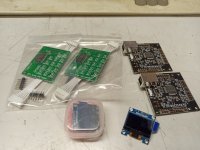
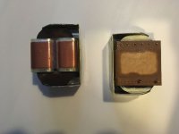
The first thing I did was paint the top plate a dark cherry. I then painted the bell cap, and the 2 PC-5 transformers. They were suppose to be more blue but for some reason the paint I used ended up looking really green. So now my Kaiju is Christmas themed. Then I glued together the wooden frame and stained it dark Walnut.
[IMG]


Here is a picture of the fully assembled back before you start wiring. Putting the Transformers on by yourself is kind of a pain in a ***.Not sure why my photo is upside down.
[IMG]


[IMG]

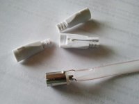
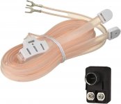
First problem occurred right at the first test to check the incoming voltage. I apparently was a little overzealous when removing the outer sheathing on the wire and had snapped on of the solid core wires internally. So I had to replace the whole section connected to the IEC.
[IMG]


I thought I had taken a photo of the PT-9 to send power to the tube sockets after wiring it up to work with the 122V I measured coming in on the previous step. Either way after they had me test the connection on the PT-9 they had me put the tuibes in to do a glow test to make sure the power was flowing to the tubes.
[IMG]


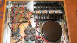
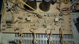
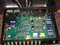
You may not like it but this is what peak wiring looks like. Only the greatest electricians can hope to wire this well.
Second screw up. While trying to remove the outer sheath on this cable I bumped my elbow and cut a full 1.5" off the end. I didn't have enough of the wire left to make a piece long enough so I had to splice and solder a short piece to the end of the cable I chopped short. Then to make maters worse I had soldered and trimmed the other end of the wire to the wrong connectors on the pot. So I had to de-solder that and the one wire wouldn't reach to the lug it was actually suppose to go to so I had the splice another piece of wire to the other end of originally to short wire.
[IMG]


Besides the 2 screw ups everything else has been going smoothly. So far my tremor hasn't been to much of a hassle on the build. Though, I start working on the C4S boards tomorrow which is where I imagine most of my struggle will be.
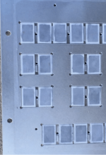
Today I started with wiring up the 9-pin sockets on the board. It went well. Even with my shake. The directions were easy to follow and understand. I accidentally touched the plastic stand offs with the soldering iron. Just need to flatten the top and everything should be fine.
[IMG]


After the 9-pin I soldered on some caps and finished connecting the 4-pin tube sockets.
[IMG]


I then added some connections between boards and caps. With that, the majority of the soldering on the panel is done.
[IMG]


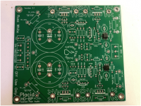
Now to start on the C4S board. The first thing I had to do was physically connect some resistors and a small potentiometer.
[IMG]


Next, I had to solder all the resistors to the board. The real MVP for helping me solder was the little clam I used to hold the board in place. With the clam I was able to better steady my hands while soldering. This is the one I used. I highly recommend buying one if you are going to be doing small precise soldering. It is only $10 and 100% worth it. https://www.amazon.com/Neiko-01902-...b+holder+for+soldering&qid=1676692928&sr=8-33
[IMG]


Added more to the board.
[IMG]


Soldered what I added. I am waiting for my smaller wire snipers to arrive so I can trim the ends closer to the board. Was suppose to get here today but UPS decided it was too cold to deliver to my farm.
[IMG]


The final addition of parts to the board.
[IMG]


The final solder of parts to the board.
[IMG]


Second board same as the first. All-in-all it took me about 2.5 hours to build both boards. So not to bad.
[IMG]

All I have left is to connect the boards to the plate then wire to match the ohms my speakers are.

After finishing the boards the next step as to connect the boards to the 9-pin tube sockets so they can run the input tubes. and
[IMG]

After fully connecting the C4S boards all that was left was to wire the amp up to run at a specific ohm level. My current speakers are 10ohm. Which falls between 2 of the wiring options, 8ohms and 16ohms. I decided to wire for 8ohms since that was closest to what I'm using. According to the manual it doesn't really matter what you wire for. Just that being closer to the ohms of the speakers could help lower the noise floor. It is pretty easy to change the ohms the amp is running at. All you have to do is change the locations the red and black twisted wires a soldered to.
[IMG]

The final wiring step. Just had to hook the red and black wires and a couple more resistors up to the speaker jacks. Which was oddly the hardest part. Since it took forever for the solder points to heat up.
[IMG]

Finally done. Here is the finished project all hooked up and working.
[IMG]

All-in-all, not counting painting, it took me 3 days to build at about 4-5 hours a day. So right around 15 hours from start to finish. The build was very straight forward and the directions were super easy to follow. Having a printed out full-color manual was a great help.


Over all the build was more difficult than the Crack with Speedball. I would say it was a moderate difficulty to build, but still very manageable. I was able to build it without any real problems with my tremor and complete lack of knowledge in electrical schematics. If you are able to follow step-by-step directions with pictures I would highly recommend giving building this speaker amp a try.


The only odd thing about the amp is that the left and right side have separate volume potentiometers. So I would recommend running it wide-open connected to a pre-amp. I currently have the amp connected to the outs on my Master-9. I believe the BeePre by Bottlehead was designed to be paired with Kaiju. Maybe in the future I will give the BeePre a try.


I will post on the sound later. Once the tubes have a chance to burn in.

Compensating for cartridge response in the phono stage

As we know, the inductance of the cartridge couples with the parallel total input capacitance and input resistance to form an RLC lowpass filter. But seeing as we're already doing all kinds of eq in the preamp, why not add a couple extra time constants to compensate for that filtering? I'm exploring a preamp design that does just that. Bad idea? Good idea? Weird idea? Curious what people's take is. I haven't built this yet, but unless you all dissuade me I will soon.

Obvious problems: (1) The cartridge might be using these poles to compensate for the mechanical response. Maybe. However then again it might not. (2) Variation from the published specs makes this an imprecise target. In simulation, this actually seems not to be a problem, and anyway variation will affect the sound without compensation as well. (3) It's not universal. Yep. However, see previous: variation within a range may still be useful. (4) You're amplifying high frequency noise. I'm not sure how much of an issue this is, but we will want to limit how far up those extra time constants reach anyway for stability reasons

Anyway, here's the design thinking:

I. Cartridge specs and input

I'm designing this for an AT VM95 cartridge. Inductance is 550mH, resistance is 485 ohms. The first step is to determine what's going on with the loading recommendations and how we want to load it. Frequency response measurements of this cart seem to pretty closely match what you would expect from the RLC filter alone. The filter achieves a Butterworth condition at around 125pF/47k input impedance, so capacitance above that will be a little peaky, and below that a little more rolled off. That seems to match what I've seen in measurements on the web. All of this indicates that it is unlikely that this particular cartridge is using the impedance to compensate for its response curve.

Since I've already thrown compatibility out the window, we may as well set capacitance and resistance to whatever we want. Since we're going to compensate the roll off, smoother curves will respond better to component differences. And anyway the circuit I'm using won't compensate anything above a Q of 0.5. There's no reason to intentionally load with capacitance at all, since we can adjust the resistor to get the desired Q. Currently my setup is a bit above this, but I'm going to guess that with a good cable I can get total input capacitance down to 100p. We're going to shoot for a Q of 0.47. The nearest resistance is 34.8k, giving a Q of 0.47 and a frequency of 21.6kHz.

II. The circuit

Screen Shot 2023-02-08 at 6.17.57 PM.png


Just the bog standard single opamp stage, with an extra resistor and capacitor. Note that in practice you will need to modify this to control DC offset, but this gets the point across. The differences from the standard circuit are (1) we are not following this with a resistor/capacitor; that time constant is being used for compensation. (2) We're adding extra high frequency boost with Cb, limited by Rb. To get these values, I wrote out the Laplace equations for current along the feedback path, then used an algebraic solver to cut through the mess, and finally hand-tweaked to get the errors where I want them. But basically (almost), Cb//R1 sets the compensation frequency, R2 sets the Q, Cb Rb should be set where you want high frequency roll off to begin, and the rest is as you would normally design it. Cb Rb has to be reasonable if you want your amplifier to be stable.

III. Results

Until I build and test it, there's no way of knowing how this will stack up in practice. But I've attached some graphs showing the electrical response, anyway. The first two show two different views of the RIAA curve including the cartridge response. The last shows the compensation curve without the cartridge, with a larger frequency range. (The roll off is way further than you'd need, but it does affect the accuracy of the frequency response much lower down.) Electrically, this stage, including the cartridge response, will be flat +- 1dB to 96kHz!!!

Screen Shot 2023-02-08 at 6.39.45 PM.png Screen Shot 2023-02-08 at 6.36.50 PM.png Screen Shot 2023-02-08 at 6.47.08 PM.png

EAR834P is not what it seems

A friend of mine has an EAR834P phono preamp in for repair and noticed two fets in the front end, wired up as a cascode with the first 12AX7. This is not what the schematics circulating on the net show. Before anyone starts it is an original unit not modified. What gives? Schematic attached.

Attachments

Molded Fiberglass Radius Port Design

I'm still chugging away on my W371A inspired design, and I am on to my 5th design for the subwoofer section. All the previous designs worked, but as I am refining the design, I am having to come up with more and more specific solutions.

I previously built a cabinet with 2x 4" ports. It works great, but I decided I need to shrink the cabinet as much as possible. This cabinet pictured is 18"x18"x48", but I want to shrink it down to 16"x 16". This will constrict the vertical area where the ports are currently installed, so I'm convinced this port design won't work right when I shrink it down.

20221105_214028_resized_1.jpg


So I experimented by building a radius port from some scrap wood and aluminum sheet. It is 8"x2.75"x30". It has a similar cross sectional area as the dual ports, but with the advantage that it exits straight out the back of the cabinet, eliminating the funky port exhaust chamber in the back of the old design.

This first test was quick and dirty as you can see. It does work quite well. There is some noticeable resonance, but likely due to the unsupported aluminum sheet. I also included a turning vane to help ensure as much of the air is traveling the same distance. (Obviously the air on the inside of the curve will travel slower and take a shorter path. This causes turbulence in pipes.) I don't know if this helps or hurts.

20221225_221410_resized.jpg


Next step is making the fiberglass version. To make it, I used my router to machine molds out of MDF. I made each from 3 slices, glued them together, sealed, primed, cleared, etc.

20230107_110523_resized.jpg
20230116_181543_resized.jpg
20230119_184611_resized.jpg


And the finished port next to the prototype. (Yes, I hot glued the port into the test cabinet. It worked. And I did add a couple screws afterward....)

20230127_200157_resized.jpg
20230127_211001_resized.jpg


I'm sure I made this a bit too good, but I am using it as an excuse to test materials and processes I will need for other projects. So it is overkill, but it is worth doing to me. Mistakes were made, but I got there in the end!

And data! These show both subs individually, and a comparison of the old and new designs. Measurement mic was placed in front of the port, so the low frequency peak is the port resonance. The actual in room response is much flatter than this looks.

Comparison between aluminum tubes and fiberglass port with no EQs or filters:

FRP vs Aluminum Ports (no EQ).png


Measurements SPL and distortion for the aluminum ports with EQs and filters applied:

Aluminum tube port +eq.jpg


Measurements of SPL and distortion for the fiberglass port with EQs and filters applied:

FRP Port+eq.jpg


(The tiny dip at ~23hz corresponds to the fiberglass port wanting to vibrate. It is largely unsupported right now, so a little bracing should fix that issue.)


That's good enough for me! I'm happy that the fiberglass port is giving me almost the same results as the dual port design, and it fixes an issue at 100hz. Best of all it will let me build my speakers without having to sacrifice by using a smaller port.

Marantz PM44SE

Hi all,

New here, just found this forum after googling my amp!

Got my PM44SE out of the loft today. Like an idiot I rigged it up and switched it on without considering that it may damp. I thought I heard a thud when I was out of the room.

Tried to play the CD player, all LEDs are on and internal fuse is ok but no sound. It usually clicks about five seconds after switch on which it isn't doing now. There was the smell of burnt dust after I turned it on the first time. It did a similar thing once efore after it had been in storage but I think that was the fuse. The solder side of the centre board looks brown on both edges near the centre. The board is still getting warm. I'm not big on electronics but am a service engineer on catering equipment and do deal with pcbs so am willing to give this a go, could do with some guidance if anyone has schematics or knowledge of this unit.

Thanks in advance.

LeeHee Audio TDA1541A DAC Digital to Analog Converter

New unused LeeHee Audio Studio TDA1541A DAC. Latest version series 8. 4x oversampling; coaxial, optical, and USB inputs. NOS mode is possible with the correct module to replace onboard SAA7220/B digital filter chip. USA model 115-volt AC input. I am the original purchaser and this item has never been used in any way so it is untested. Top cover has 2 spots where the factory anodizing is slightly uneven where it looks like scratches but they are not. No documentation came with this DAC, so I do not know if a software driver is needed for USB capability. USB module is XMOS U8 based. $400 plus shipping.

I have an NOS module along with a 96kHz digital receiver chip available.

Technical specs: Digital input 16-bit 32KHz, 44.1KHz, 48KHz; Frequency response: 10Hz~22kHz +/-0.5dB; Dynamic range: 96.5dB; Total harmonic distortion 0.002% @1kHz; Intermodulation distortion: 0.004% @12-14K; Channel separation: -97dB.

Sold "as-is" and no warranty is expressed or implied. No returns or refunds. Sells and ships to USA residents only.

IMG_4390.JPGIMG_4392.JPGIMG_4385.JPGIMG_4401.JPGIMG_4399.JPG

Multi Configurable Testing PCB for Papa’s SIT-PMosfet, SIT-NMosfet MUFF and DEFiSIT Amplifier

Papa has published so many variants of SIT amplifiers. A question will always pop up, which one sounds better or which one I should build. The standard answer will always be: you need to try them all, or it is worth to building them all.
The multi configurable Testing PCB is trying to satisfy them all.
I wish your experienced DIYER can chime in and we can make it better. At end of it, I will order PCB and test build it. All design files for it will be public here and everyone can use.
Configurable end stage
AMP1, SIT N-Mosfet MUFF, close Jumper for NMos MUFF, open Jumper for PMos MUFF, jump and short all pins PMOS Conn
AMP2, SIT P-Mosfet MUFF, open Jumper for NMos MUFF, close Jumper for PMos MUFF, jump and short all pins NMOS Conn
AMP3, SIT P-Mosfet DEFiSIT, close Jumper for NMos MUFF, close Jumper for PMos MUFF, jump Pin1 and 3 of NMOS Conn, bridge SIT Conn Pin 2 and NMos Pin2
Configurable power
V+ and GND: V+ on Pin3 of Configurable PW Conn, jump Pin2 and Pin1 as GND
V- and GND: V- on Pin1 of Configurable PW Conn, jump Pin2 and Pin3 as GND
V+/- and GND: connect as shown
Speaker connector, you can try different Rs and Rm for different THD and 2nd and 3rd ratio
Interchangeable front end
The famous Fjet buffer is designed in. four connecting points are designed, V+, V-, Output and GND. Using bronze spacers. A daughter board can be build up and add-on. If not needed, just not put Jfets on, then your external drive board can be used.

The final power board schematics for 48V SMPS is in the post #19.
The final amplifier schematics is in the post #20.
The measurement started from the post #33.
The zipped KiCad projects for the amp and power are in the post #36, feel free to use them.
The +/-24VDC power supply with Mean Well DC-DC module is added in the post #41
The FE with IC headphone amp + Edcor transformer is added in the post #43
The FFT measurements for output power at 1, 5 , 10, 15, 20 W are added in #44/#45
The SIT amp sounds super with Pass BA-3 FE. You guys need to try it!
A Salas DCG3 front end and DCSTB power reg were built to drive the SIT amp. This is my 3rd FE in the testing in #50.


If I am not mistaking, the build is the first DIY of Papa's SIT MUFF with N-Mosfet. As Pa said, big N-Mosfet is easier to get and have more choices. And they are more consistently built than P-Mosfet, based on my very limited 4 samples testing.

The sound of the amp is the best so far in my DIY experiences. I will listen it for long. So I won't test the PCBs boards for other builds in short time.

After I built F4, DefiSit, Lufet and SIT MUFF and listen all of these passive follower without gain, I have an impression(Maybe I am wrong). They sound little bit too lazy. Like a very passive dancing partner, it needs a very active, vivid and forceful front end to drive it and bring it to life.

I hope the upcoming Pa's front end can bring it.

Attachments

  • shcematics.png
    shcematics.png
    65.6 KB · Views: 615

  • Locked
Your contribute to Audio evolution

Hi,

Whether you are an enthusiast, a technician, or an engineer, a physicist, or a mathematician, a brilliant designer or a simple listener of your favorite Music which was/is your contribute to the evolution of Audio?

Or, besides yourself who was/is in your opinion a real contributor to Audio for a good sound in the design of amplifiers or loudspeakers or any device, and why?

My feeling is that the real news in Audio design are few, or am I wrong?

  • Locked
Measurement of high end capacitors versus standard quality foil capacitors

Here the article of the other forum:

Capacitor upgrade in crossover - Is it audible?

They say most of the hype about high end capacitors is marketing hype - no differences in measurement.
I would really like to hear the opinions of the members of this forum.
Many thanks in advance for your interest about this thread, Stefano

  • Locked
Threads or user deleted / unreachable ?

I cannot reach following thread : https://www.diyaudio.com/community/...-composite-amplifiers-based-on-lm1875.382575/ which is referenced by many thread, same for the TDA7293 version : https://www.diyaudio.com/community/...iers-based-on-tda7293-94.379506/#post-6850255, even OP seems to have disappeared, I think it was kaltecs

I have been able to access those threads during last month, what's happened since then ?

thanks

Large circular MEH - which waveguide profile to use?

Since I saw the A For Ara H2 speakers, I feel the urge to try a better horn than the usual flat board construction for a MEH - and compare it to the prototype I am working on right now. It would be most probably a combination of CNC machined plywood and foam. My space is limited to a box of 95 x 95 cm baffle and depth of around 70 cm in total. A round mouth looks cool in a square baffle, a square/rectangular waveguide with smoot transition would also work.

The wonderful ATH tool is the natural choice, however it presents so many options, that I am a bit lost there. I would appreciate any suggestions on which profile to use as a start, with 1.4" throat, coverage angle around 85 degrees round or around 85x65 rectangular - to be comparable with the flat board prototype.

For Sale Buffalo-IIIsePro38 Complete Kit

SOLD- ALL ITEMS SOLD

Twisted Pear Buffalo-IIIsePro38 Complete Kit Combo

**Plus Added Bonus 2/17/23
JLSounds I2S over USB v.III
(see post #4 )

I bought this complete kit and have decided I will never build this.

Buffalo-IIIsePro38 Complete Kit Combo
[1] Buffalo-IIIsePro38 2-Channel DAC** w/Full Series Regulator Set (newest SR version)*
[1] Centaur 2A Power Supply Complete Kit
[1] Mercury Balanced I/V Stage v1.1 Kit
[1] Placid HD BP Power Supply Kit V2.1

(1) AVCC-SR Dual 3.6V Series Regulator Module*
(2) TridentSR 3.3V Series Regulator Module*
(1) TridentSR 1.3V Series Regulator Module*
**(Assembled and Tested by TPA)

No items have been soldered, modified nor even removed from original packages: All are as initially received from TPA.
Prefer to sell as 'Combo' ONLY. $350. Free US shipping, contact me for outside US
SOLD- ALL ITEMS SOLD


SOLD- ALL ITEMS SOLD

Attachments

  • 1675351183009.png
    1675351183009.png
    102.3 KB · Views: 512
  • 1675351229370.png
    1675351229370.png
    100.1 KB · Views: 501
  • 1675351303667.png
    1675351303667.png
    143.4 KB · Views: 522
  • 1675351365408.png
    1675351365408.png
    79.8 KB · Views: 514
  • 1675351528946.png
    1675351528946.png
    356 KB · Views: 505
  • 1675351551923.png
    1675351551923.png
    148.7 KB · Views: 516

FM Throw Antenna Dipole with Vintage IEC FM (RFT) Plug (DIN45316, 240/300 Ω) - where to order ?

In this old thread under
https://www.diyaudio.com/community/...ole-wire-and-for-disassy-e-g-quad-fm3.161284/
I ask for the plug itself:
Now I ask for throw antenna dipole with integrated IEC (RFT) plug for use on vintage FM tuners without possibilities of mounting an outdoor (yagi) antenna.
Main reason therefore is the fact, that such antennas with integrated coax plug don't work in the right manner due absence of a RF transformer (balun) from 240/300Ω to 60/75Ω (go to image No 1 and 2).
One solution is the use of a coax plug with integrated balun (go to image No 3).
Unfortunately not all vintage FM tuner use coax antenna inputs (go to the last both images).
Sometimes there are such Coax antenna inputs additional present, but not enough space for a coax plug with integrated balun (go to image No 9).

Therefore I want to know suppliers of FM throw dipoles with integrated plugs according D45316 (go to images No. 4-7).
Thank you very much for sending supplier URL's from Europe.

Attachments

  • FM Throw  Dipole+Koax-Plug without Balun-II.jpg
    FM Throw Dipole+Koax-Plug without Balun-II.jpg
    48.4 KB · Views: 196
  • FM Throw  Dipole+Koax-Plug wihout BALUN .jpg
    FM Throw Dipole+Koax-Plug wihout BALUN .jpg
    36.2 KB · Views: 179
  • FM Throw  Dipole+Balun-Koax.jpg
    FM Throw Dipole+Balun-Koax.jpg
    67.4 KB · Views: 199
  • FM Throw  Dipole+Plug DIN45316-IV.jpg
    FM Throw Dipole+Plug DIN45316-IV.jpg
    48.8 KB · Views: 208
  • FM Throw  Dipole+Plug DIN45316-III.jpg
    FM Throw Dipole+Plug DIN45316-III.jpg
    54.3 KB · Views: 223
  • FM Throw  Dipole+Plug DIN45316.jpg
    FM Throw Dipole+Plug DIN45316.jpg
    524.7 KB · Views: 240
  • FM Throw  Dipole+Plug DIN45316-II.jpg
    FM Throw Dipole+Plug DIN45316-II.jpg
    124.2 KB · Views: 271
  • quadfm33.jpg
    quadfm33.jpg
    38.5 KB · Views: 202
  • Beomaster 5000.jpg
    Beomaster 5000.jpg
    123.3 KB · Views: 173
  • Beomaster 5000 FM Tuner.jpg
    Beomaster 5000 FM Tuner.jpg
    77.6 KB · Views: 183
  • Beomaster 5000 IEC DIN45316.jpg
    Beomaster 5000 IEC DIN45316.jpg
    69.5 KB · Views: 179

Headphone Amplifier Circuit Design

I've always wanted to build my own headphones and was curious if anyone here has any experience or tips as I am not sure if the circuit can work.
The components I will use are as follows:
Breadboard
Battery
ceramic capacitor
Resistors
polar capacitor
BC237 NPN transistor (datasheet)
BC239 NPN transistor(BC239 DATASHEET)
MIC
Audio Jack

Here is the circuit.
1676876812086.png

output capacitor in OTL headphone amp

Hello,
What do you think of the on/off dc transient caused by output capacitor charge/discharge in OTL amps? The following screenshots are made on a 300 Ohm termination resistorduring on/off. With the headphones connected it should be much smaller since the DC resistance of a 300 Ohm impedance headphone is much smaller, but still, the same charge goes in/out during on/off.
Don't you think it will damage the headphone sometime?

The cap I use is 470 uF.
Thanks,
JGKépernyőkép 2023-02-12 185919.jpg
power_off.jpg
power_on.jpg

Unloaded HT voltage rise.

I have an single ended amp I'm working on that reuses a power transformer from an old rca-rs188 console. I'm in the planning filter stages using psud2 and I'm wondering what I should expect voltage wise in my new circuit.
The HT is rated at 290 volts @100ma after the 5y3 with an 80uf E-Cap. (No filter network) according to the original schematic.
PXL_20230222_224635004.MP.jpg

What I've measured is
Primary-4.32 ohms
Secondary-80 ohms per leg unloaded 302 volts 604 total.
The heaters are also running hot a 7 volts. (Unloaded also)

The new design calls for a b+265v.
PXL_20230222_224711020.MP.jpg

Edit From what I can gather a NOS RCA ny3gt has a voltage drop anywhere from 20 volts to 50. (At what current I'm not sure)
My original prints say 290@100ma and I'm getting 302 unloaded. That's not as big of a voltage drop as should be expected.

12CG7/12FQ7 direct swap for 12AU7?

Hello. I recently came across a pair of NIB Ultron 12CG7 Special Quality tubes made in West Germany.

I can’t find much info on this tube and wondering if it can be a direct substitute for 12AU7?

My amp is a Rogue Audio Hydra. I’m currently using 12BH7 tubes in it.

Would be grateful for any advice.

Thanks legends!

Attachments

  • 99F866EC-597B-4E40-90B5-26AB82432EA0.jpeg
    99F866EC-597B-4E40-90B5-26AB82432EA0.jpeg
    99.6 KB · Views: 189

Restoring Threshold SL10, SA2 and S450e

Hi All,

This is my first post on this forum, so hello everybody. I read various useful threads during the years, but this time I need some direct suggestions from you Threshold lovers. In the last 2 years I became the owner of an SL10, a pair of SA2 (optical bias) and a S450e (not sure if it has the optical bias). They are keepers, so I am thinking to let them restored, and so I would like to have some suggestions regarding what I have to do to keep them alive and at their top quality.

The SA2 seem to work just fine, very good control of the speakers and sweet if I don’t push too much, then a bit harder and less warm at higher volumes, but I think it’s normal . The SL10, which I use with a top level Sondek LP12, is working well: very open, detailed, but sometimes seems a little harsh / dirt sounding, especially on some LPs. But again, maybe in those cases it’s just the recording. However sometimes sibilance in voices in particular on “Ssss”, are quite annoying. But again, in general I like it for its transparency, that just sometimes seems to get lost, or better to lose some transparency, in some difficult passages with plenty of instruments playing. The S450e quite similar to theSA/2, just a little bit less sweeter but very pleasing, with great control on speakers. Here again is some passages where there is plenty of instruments, the sound became a little bit confused, more dirt. Sibilance “Ssss” are present much more than in the SL10. In the 450e there is one thing that worries me and has to be addressed: a very low level noise in the right channel, that can be heard going near the speaker, in mid frequency in particular I can hear a noise similar to boiling water, if this could be an example.

So after this long description, I ask you, what would you do in my shoes? I don’t do the restoring by myself but a friend of mine does, if I provide the “instructions”, For the SL10 I found a great thread in this forum with all the tips to follow step by step to get it restored. I didn’t find something similar for the SA/2 nor the 450e, so do you have any suggestions? For example, changing just the electrolytics and leave all the rest as it is? I would like to be conservative with the restoring and change only the things that after so many years have to be changed for sure. What do you suggest?

For the SL10 I found this

https://www.diyaudio.com/community/threads/recapping-threshold-sl-10.114154/

Regarding the amplifiers, my idea was to listen to your advices , eventually change what has to be changed for sure, and then let them checked for a proper bias setup. Right now after a few hours the temperature seems ok, i.e. a little bit warmer than 37 degrees...

I hope I was clear enough, sorry English is not my language...

Giacomo

Reed-relay Volume Control and Preamp

Hi Everyone,

This is my first post, so please bear with me.

I've just completed my first major audio project. The power amplifier comprises of two LJM L12/2 Power Amplifier modules and an LJM power supply/protection board, all built from kits from AliExpress.

The preamplifier is of my own design. It uses reed relays to select the input and as a volume control. I'm really pleased how well it works. The reed relays give a nice smooth control of volume in 1dB steps with no audible clicks (mechanically or electrically). Has anyone else tried this?

Each channel has a 3-way input switch and 6 switched attenuators of -1dB, -2dB, -4dB, -8dB, -16dB and -32dB. By selecting them in binary combinations, 64 levels are available in 1dB steps. LM4562 opamp buffers provide a constant impedace source to the next stage to stop interations between them. See attached circuit diagram.

LM317 and LM337 regulators provide +/-15v power for the opamps, +12v for the relays and DAC module, and +5v for the processor.

I'm using a Raspberry Pi Pico to receive the front pannel buttons and infrared remote control and control the relays, although an Arduino or PIC would work just as well. A 4-character alphanumeric LED display shows the volume and input source. The software is pretty simple and written in Python.

Frequency response of the preamp is 7Hz to 500KHz at -3dB. I don't have equipment to measure the distortion or noise, but expect it will be extremely low. It sounds great to me, but of course I'm biased.

I'd be interested to hear what everyone thinks, and especially ways in which it could be improved.

Gary

LJM L12/2 power amplifier:

PXL_20230202_191624191.jpg


Reed Relay Preamplifier:

PXL_20230216_142348267.jpg


PXL_20230214_184456793.jpg

PXL_20230216_142903014.jpg

Attachments

  • Like
Reactions: manniraj

FS: X-Altra MM/MC phono preamp kit

SOLD !

Trying to offload some of my projects on which I am unable to find time to work.

This is a full kit, all parts you need to built Bonsai's X-Altra MM/MC phono preamp. Well, it may be missing one standoff and some wires for the switch.
Kit includes proper case and rear panel, PCB and a big bag of parts including hard to get ZTX 851 and ZTX951. Transistors are measured so you can pick matching pairs.
There is a bunch of small SMD parts to solder so choose your battles wisely.
Project info below:
https://www.diyaudio.com/community/threads/bonsais-x-altra-mc-mm-phono-preamp.358956/

Asking SOLD ! shipped to lower states.

Thanks


IMG_0330.JPG

6N1-J Chinese tube amp

Good day,

sorry if it's been already discussed but it took two years to find out what kind of tube could replace my 6n1-j on my Chinese affordable amp

The answer is:
ECC85

Confirmed by the supplier and tested right now on my amp with a pair of 6L6 and 5U4 rectifier

I guess this amp is sort of a clone of Elekit

So I guess next time I won't search all the Internet to find my answer. Just remember that I put a post here a message

Here the answer for Yulu amp gen1:

hello dear customer
wish you have a nice day
Rectifier 5Z2P: 5AR4, 5Z3P, 5U4, 5R4
Front stage push tube 6N1J: former Soviet Union 6H1N, European and American ECC85
Power tube EL34: 6P3P, 6L6, KT66, KT88
The above are replaceable tubes


Enjoy!

350uF 350VDC low ESR Screw Terminal Cap Needed

Looking for a low ESR version of Sprague Powerlytic caps from the 1980s to upgrade an amplifier so that after market add on bypass caps can be removed. (The bypass caps are the size of orange juice cans and customer added them to bypass audio leakage into power supply.)

The closest mechanical dimensional fit is Cornell-Dublier CGS331T350R2C with the right dimensions and capacitance, but only available in quantity multiples of 100!

Can anyone suggest a source where I can get four of these without spending thousands of dollars?

Mod Squad power supply voltages

Anyone here own a Mod Squad Phono Drive? Since moving house I have lost the power supply for my Mod Squad Phono Drive Deluxe.After several months now I can't see it turning up.
I would very much appreciate help in assisting me with a schematic or simple diagram for the same.
As far as i can determine it is an a/c output. if another owner could check the voltages for me that would be great.
It shouldn't be to hard for me to make up an ac to ac supply however I don't know if a soft start circuit is used or how the earth lifting switch is employed again a quick peek inside your own power supply and a photo would be much appreciated
Kind Regards Robbie

Oversamplers, DACs and SRCs in the parts bin -- combos, project ideas?

Here's what I have:

Dedicated oversampling/interpolation ICs:


DF1704 (Burr-Brown digital oversampler, dedicated DF chip, from 2001)
http://www.dddac.de/files/DF1704.pdf
(Unfortunately, I sold my pair of PCM1704 many years ago, I think the DF1704 should okay work with other DACs)

NPC SM5843
http://vasiltech.narod.ru/files/SM5843A.pdf
(It doesn't do I2s, so that might be a big issue)

Philips SAA7220 A or B
(in use currently in several active projects, couple with -- what else -- a TDA1541(A))

DACs:


PCM1732 (a combo of HDCD filter + delta-sigma DAC, from 1999)
https://www.datasheetcatalog.com/datasheets_pdf/P/C/M/1/PCM1732.shtml

AD1862 (pair)

PCM1792
PCM1794
PCM1795
PCM1796
PCM1798

CS4398

Philips TDA141 (A)
Philips TDA1543
Philips TDA1545A
Philips 1387
Philips TDA1305T

SRCs:

CS842
etc.

Receivers:


CS84xx (12, 14, 20)

Adapters:

Xmos and "Amanero" USB-I2S boards.
============

Initially, I just want to breadboard some of these devices together -- quickly. And want oversampling/interpolation and/or even "upsampling".

I want the breadboard unit to be functional -- doesn't have to sound spectacular. I can work on that later.

My ultimate combo wish is to pair the DF1704 to AD1862 (pair). But I want to stay in the I2s domain because my main input will be USB-to-I2s. And I think the the AD1862 only allows Binary Two’s Complement, MSB-first, right-justified audio data (input). Also, the AD1862 has to be trimmed and and then be followed by I/V and LPF. And all that makes for a messy breadboard!

Yes, I do realize that several of the standalone DACs have built-in DFs. But upstream DFs and SRCs can, nevertheless, "upsample" (condition) the digital data so it enter the DAC more ... cleanly .... yes ???

About SPIDIF:


Well, my Linux PC and Laptop -- my main file and Foobar source -- can't output SPIDIF ... but if SPDIF is the best sonic option (and not USB), then I'll have invest in, say, a high-quality PCIe motherboard mounted SPDIF adapter.

Looking for options ... suggest some in replies. Thanks!

Digital Tachometer for record player (LCD display)

Avast Gents, happy new year.

I have been contemplating a tachometer for my record player with a digital readout LED or LCD--(making one as opposed to buying one as we know they already exist a la roadrunner... but are to expensive for my meager budget😱)

There are lots of examples on the new of using ardunio and a hall effect sensor but these are for drill and lath speeds, not 33.33RPM as we would require.
Numerous cheap (and nasty?) -- Car tachometer modules abound on e bay -but are they accurate enough for record player use??.
Some interesting propitiatory modules were about but when contacted the makers do not produce these items any more!

What would be great is an ardunio based (accurate) Tachometer with a hall effect sensor, and the possible option of using a touch screen to turn the record player motor on/off which could via the arduneo switch a relay on/off---(think project had this in one of there high end turntables?)

I have the brains to buy the items, but to code this...nah i be flabbergasted!😀

Is anyone of you good gents (or ladies..i aint proud) shed any light on such a project.... i am aware that that git hub can download library's for buttons on a LCD..and code exits for tachometer functions (counts time between magnet pulses and works out RPM from that?)...but how to integrate it all from a newsboys point of view??
Fingers crossed then.

cheers ..johnny

Korg Nutube preamp noise issue.

Hi all, I’m new here to please be gentle.


Wondering if someone could help me,
my lovely partner bought me a Korg Nutube pre amp but unfortunately I’m having a problem with it.

I followed the diy guide and it works and plays but there is quite a lot of hiss coming through both speakers when it’s turned on, it also gets louder when the volume is increased.

Is there a check list I can run through to try and eliminate it?
Many thanks.

Lloyd.

Sanken 2SA1216 2SC2922, Genuine and Fake pictures

HTML:
<head>
<style>
<!--
.wysiwyg {
 PADDING-BOTTOM: 0px; MARGIN: 5px 10px 10px; PADDING-LEFT: 0px; PADDING-RIGHT: 0px; FONT: 10pt verdana, geneva, lucida, 'lucida grande', arial, helvetica, sans-serif; BACKGROUND: #f5f5ff; COLOR: #000000; PADDING-TOP: 0px
}
P {
 MARGIN: 0px
}
-->
</style>
</head>
<p><font size="5" face="Arial">These pictures, hope to help you choose, Left 
Genuine, Right Fake:</font></p>
<table border="1" width="100%" id="table1">
 <tr>
  <td width="50%" align="center"><b>
  <font size="5" face="Arial" color="#008000">Genuine</font></b></td>
  <td width="50%" align="center"><b>
  <font size="5" face="Arial" color="#FF0000">Fake</font></b></td>
 </tr>
 <tr>
  <td width="50%" align="center">
  <img border="0" src="http://i1017.photobucket.com/albums/af292/Sunmansli/transistor/2SA1216-2SC2922/DSC_0585.jpg" width="450" height="338"></td>
  <td width="50%" align="center">
  <img border="0" src="http://i1017.photobucket.com/albums/af292/Sunmansli/transistor/2SA1216-2SC2922/DSC_0583.jpg" width="450" height="337"></td>
 </tr>
 <tr>
  <td width="50%" align="center">
  <img border="0" src="http://i1017.photobucket.com/albums/af292/Sunmansli/transistor/2SA1216-2SC2922/DSC_0589.jpg" width="450" height="338"></td>
  <td width="50%" align="center">
  <img border="0" src="http://i1017.photobucket.com/albums/af292/Sunmansli/transistor/2SA1216-2SC2922/DSC_0582.jpg" width="450" height="338"></td>
 </tr>
 <tr>
  <td width="50%" align="center">
  <img border="0" src="http://i1017.photobucket.com/albums/af292/Sunmansli/transistor/2SA1216-2SC2922/DSC_0588.jpg" width="450" height="338"></td>
  <td width="50%" align="center">
  <img border="0" src="http://i1017.photobucket.com/albums/af292/Sunmansli/transistor/2SA1216-2SC2922/DSC_0584.jpg" width="450" height="338"></td>
 </tr>
 <tr>
  <td width="50%" align="center">
  <img border="0" src="http://i1017.photobucket.com/albums/af292/Sunmansli/transistor/2SA1216-2SC2922/DSC_0604.jpg" width="450" height="338"></td>
  <td width="50%" align="center">
  <img border="0" src="http://i1017.photobucket.com/albums/af292/Sunmansli/transistor/2SA1216-2SC2922/DSC_0599.jpg" width="450" height="338"></td>
 </tr>
 <tr>
  <td width="50%" align="center">
  <img border="0" src="http://i1017.photobucket.com/albums/af292/Sunmansli/transistor/2SA1216-2SC2922/DSC_0605.jpg" width="450" height="338"></td>
  <td width="50%" align="center">
  <img border="0" src="http://i1017.photobucket.com/albums/af292/Sunmansli/transistor/2SA1216-2SC2922/DSC_0609.jpg" width="450" height="338"></td>
 </tr>
 <tr>
  <td width="50%" align="center">
  <img border="0" src="http://i1017.photobucket.com/albums/af292/Sunmansli/transistor/2SA1216-2SC2922/DSC_0620.jpg" width="450" height="338"></td>
  <td width="50%" align="center">
  <img border="0" src="http://i1017.photobucket.com/albums/af292/Sunmansli/transistor/2SA1216-2SC2922/DSC_0615.jpg" width="450" height="338"></td>
 </tr>
 <tr>
  <td width="50%" align="center">
  <img border="0" src="http://i1017.photobucket.com/albums/af292/Sunmansli/transistor/2SA1216-2SC2922/DSC_0624.jpg" width="450" height="337"></td>
  <td width="50%" align="center">
  <img border="0" src="http://i1017.photobucket.com/albums/af292/Sunmansli/transistor/2SA1216-2SC2922/DSC_0631.jpg" width="450" height="338"></td>
 </tr>
 <tr>
  <td width="50%" align="center">
  <img border="0" src="http://i1017.photobucket.com/albums/af292/Sunmansli/transistor/2SA1216-2SC2922/DSC_0621.jpg" width="450" height="338"></td>
  <td width="50%" align="center">
  <img border="0" src="http://i1017.photobucket.com/albums/af292/Sunmansli/transistor/2SA1216-2SC2922/DSC_0616.jpg" width="450" height="338"></td>
 </tr>
</table>

Proper biasing Threshold SA/1s

Recently acquired a couple of vintage Threshold SA/1s (two from 1985 and two from 1988) both with optical biasboards (the one from 1985 is updated)
Do have the biasprocedure from Threshold called the 'Standard Amplifier Bias Procedure' from February 1991.

ADJUST1.jpg
Threshold Bias Requirements.JPG

Wish to check the bias and found an old post from myself regarding this matter but I wonder if it's the right (alternative) way to do this.
"I got the best result with popping out one of the railfuses and connecting the leads of a multimeter in high ampere mode (usually 10A) instead.
With the proper connections in place you start the amp and you can monitor the quiescent current for approx. two hours.
What you will observe is a rapidly ascending bias (for shortening the warmup time) over 4 Amps in the first couple of minutes and then after it peaked it will gradually taper of to the proper setting of approx. 3A.
To get the 160 Watts of Class A rating @ 8 Ohms you need 3.2 Amps of bias
(3.2 x 2) = 6.4 (because it's a complementary design not single ended one) then ((6.4 x 6.4) x 8)/2 = 163 Watts. If the heatsinks stay around 50 degrees Celcius in two hours you're basically okay."

When I read this table from Threshold it seems that I'm totally wrong in case of the railfuse currentfigures in the above quote.

s2-3-500bias shrunk.jpg

Or should I follow the standard bias procedure and take a emitterresistor somewhere in the middle of the crop?
  • Like
Reactions: Mikerodrig27

Threshold SL10 stepped attenuator

Would someone please let me know if a TKD 2p65cs 100k ohm stepped attenuator would work reasonably well in a Threshold sl10 mated to a Threshold s/500 optical bias amplifier? The s/500 input impedance is 75k ohm; the sl10 was originally fitted with a 22k ohm Nobles pot gauging from the schematics. This sl10 was later updated with a relatively cheap 20k ohm dact-type generic stepped attenuator and it has an incessant problem with static and the mechanical steps are less than stellar in mechanical and sonic precision.

Alternatively, is there an alternative attenuator suiting an sl10, other than the relatively less costly ALPS-type or dact-type, that would work well?

Thanks for your help and information.

Attachments

Modushop Enclosure Issues....

I have ordered and assembled 2 different enclosures from Modushop. I have mixed results with both. First, I want to say that I'm not slamming these enclosures I'm actually quite thankful they are available. It does seem like there is some issues with QC from the manufacturer though. Most of the issues are simple fastener issues. My first 1U preamp enclosure uses countersunk style fasteners that are fitted to non-countersunk holes. This looks like an afterthought bc the heads stick up above the level of the enclosure.
The second 2U passante was purchased with the subfloor option. First it is not as stout as I expected. Anything halfway substantial mounted to it will cause it to bow. But the biggest issue is that the wrong fastener size was sent for the top and bottom plates for mounting. It calls out #8 screws on the instruction sheet but they sent #6, so none of the screws tighten up they just spin. So now I have to go out and get my own screws. Just my two cents.

Why exactly drivers built for guitars are bad idea for home HiFi Speakers?

I was wondering why is this the case: specific reasons. For example, I read about great qualities of Alnico magnets, esp. in the bass region.
Celestion happens to have 12 inch driver which uses Alnico but its marketed for guitarists.

So why its generally not used in home audio?

I see that such drivers dont play that low for their size comparing to Hifi drivers? Is t true and is it the real reason?

The other thing Ive heard has something to do with surround stiffness and that Guitar (and PA) drivers sound poor at somewhat low SPL levels... again, true or rather not?

Subwoofer drivers with Neodymium are now quite expensive, but these Celestions are not that pricey, thats why I ask.

I will be grateful for your insights.

Hartke LH1000

Hi

When I turn on the amp, channel 2 relay clicks in about 4 secs and they is sound on this channel. Channel 1 relay takes about 17secs to click in. I have checked all the components on this power amp board and all seem fine. What could cause this delay in turning on. Can someone guide me on what are the components that cause this time delay.

Thanks

Attachments

HELP! How can I mount speakers WITHOUT SCREWS?

Since this forum is filled with MUCH smarter people than myself, I’m sure someone’s got advice for me!

GOAL: I’m building a desktop/Bluetooth speaker that contains two 4” Dayton Audio woofers, and two 2” ring radiator-style tweeters. I crafted a front baffle/panel out of Red Oak, and routed recesses for the both the drivers and tweeters, to get them as close to flush as possible…

QUESTION: How can I securely mount the drivers to the inside/back of the baffle WITHOUT SCREWS?

* I would prefer to simply ”glue” or adhere them to the inside of the baffle with some sort of strong glue/adhesive, but I’ve no idea what would work best. Any ideas?

* I’ve also considered crafting some rings out of wood/MDF and using those as “clamps” of sorts - by mounting them over the outside of the speaker basket, then attaching the rings to the inside oak baffle.

I attached some photos of the speakers/parts, as well as a mockup of my goal. If anyone has some advice, I’m all ears! Thanks in advance!!


FF22CCFC-7670-479F-8502-1914832878BA.jpeg

Attachments

  • 3EDBE907-A3C1-44B2-8CB3-C5216C236D88.jpeg
    3EDBE907-A3C1-44B2-8CB3-C5216C236D88.jpeg
    562.1 KB · Views: 363
  • C6B82973-22AC-4F5D-B9B6-5E0D553D50C4.jpeg
    C6B82973-22AC-4F5D-B9B6-5E0D553D50C4.jpeg
    579.4 KB · Views: 187
  • 0C9B1030-EB5A-47C0-913A-03AAB258ADDE.jpeg
    0C9B1030-EB5A-47C0-913A-03AAB258ADDE.jpeg
    509 KB · Views: 293

Griffin Aperiodic 27

Griffin Aperiodic 27 (1980's)

Design by Paul Griffin, made by H.K. Griffin & Co (Electronics), West Bromwich, UK

KEF B200 Bass Unit, 25Hz ~ 2.3KHz
KEF T52 Mid/treble unit, 1.6KHz ~ 7KHz
Coles/S.T.C 4001K hand-picked super tweeters, 6.5KHz ~ 25KHz

Power handling > 70 watts continious, 8 ohms

I purchased two sets of these back in the early 80's from a fancy HiFi store in Redcar, Yorkshire, England. One set has been in storage for over 30 years, the other set has been used from time to time. I recently connected to a modern Marantz amp and really enjoyed the sound in a larger room. What I have noticed recently they sound so much better at slightly elevated sound levels in a larger room and good quality amp.
Their agility and accuracy with Jazz, Classical, and Vocal music is astonishing,

Attachments

  • Giffin-27-SpeakerBrochure1.jpg
    Giffin-27-SpeakerBrochure1.jpg
    747 KB · Views: 211
  • Giffin-27-SpeakerBrochure2.jpg
    Giffin-27-SpeakerBrochure2.jpg
    704.4 KB · Views: 224
  • Giffin-27-Speakers.jpg
    Giffin-27-Speakers.jpg
    610.7 KB · Views: 264

Gr33tings

Greetings, I am newbie here and to this type of thing. I've always been the type to go bust my rear to get nice new audio gear. Mostly because of the situations that I have been in for most of my life. Still am in a way but now it's more because of space than people. I'm 51 and on my own for the first time since my early 20s and even then it was only for a short time. Now my issue is that I can only afford to live in a small (<700sq/ft) apartment and I have to be somewhat careful to not bother other tenants who are generally nosey and have nothing better to do than gossip and complain about what I am doing. I also have no storage or other means to keep much of anything. I do rent a small storage unit at a facility but that's only good for keeping stuff, not for working or tinkering with anything and it's a few miles away so it's not convenient to transport stuff around between here and there while working on a project. I still do some small stuff that doesn't require a lot of space nor make too much noise at night. I have a makeshift hobby table set up in my room and a few small projects to work on when I have time. I mostly refurbish decent speakers and the occaisional cleaning and minor repair jobs to receivers that are worth saving.
I'm in Denver, CO. U.S. and am a commercial construction paint job foreman by trade but music and good audio equipment has always been my passion. I am also an amature gunsmith and general firearm enthusiast and I take old decent quality mountain bikes and update the components, ride them for awhile to work the bugs out and then either sell them or trade for audio equipment, vinyl records, or anything to do with guns. I can paint and otherwise refinish just about anything as well so that helps out in all the things I play around with.

DB9 output

I am not sure where to post this, I am fighting for over a week trying to get a XP OS operational to use Glassware Audios tube amp design software and PSUD (the version for Macintosh is very basic and does not allow for circuit changes). I got a DB9 to HD15 adapter, then plugging the HD15 into a television (DVI to HDMI works fine).

I have no signal is coming into the television according to the television. I can hear the computer running through the start up, so would think there be something. I also tried both ports, the one near the top and the one near the bottom, no change.

The computer has not been used in years, was functioning just fine, though would storage cause the graphics card to fail? The storage unit got super hot over the summer.

The only other variable besides the television (used to be using a cathode ray tube monitor) is the new VGA cable.

Is the signal coming from DB9 too weak to supply a television?

Is there a way to check for signal from the computer?

Thanks in advance! 😀

MTX 92001 pictures of components?

I have a nice mtx 92001 that came in and there are two sections of the board with visible damage. Unfortunately there are significant amount of SMD components missing and/or obliterated.

I was hoping someone would have a picture of these sections of the board they might be able to share.

Thank you in advance

An externally hosted image should be here but it was not working when we last tested it.


And

An externally hosted image should be here but it was not working when we last tested it.

8.8L small Markaudio CHR-70 build - first time speaker designer/builder

Hey all, long time follower first time poster here! Wanted to share my first speaker design/build and get your constructive feedback!

Concept: A small speaker enclosure of 8.8L to be used as desktop/bedroom speaker and potentially a surround speakers for Dolby Atmos mixing studio (hence wide baffle design and front facing port opening).

Specs as simulated attached (VirtuixCAD):
  • Markaudio CHR-70 (Gen 3)
  • 8.8L (0.31 cuFt)
  • Port Area: 4.5" (29 cm)
  • Port Length: 12" (30.5 cm)
  • Port Opening: 1/2" (12.7mm)
  • Box/Port FB: 51.1 Hz
  • F3: 53.2 Hz
  • Additional notes:
    • Will most likely be used with plate amp and DSP (baffle step correction and minor room management to be implemented via DSP)

Few questions:
  • Aside from front facing port, what other factors should one account for a near or on wall design?
  • Slotted port: my port narrow dimension is 1/2 inch. Could this narrow dimension port pose noise/chuffing issue as it does in tube vent thats are smaller diameter? At full power of 20 watts velocity is at around 11 m/s at 43 Hz
  • And although I do not see this speaker being driven with more then 8-10 watts max, excursion simulation is not laving me with much headroom... any potential remedies a side from changing/looking for a new driver?

I am new to this but have dove head in to speaker design and it is such a fascinating field! Being a long time audiophile as well as music "home" producer I am very excited to be learn!

I very much look forward to your feedback! Thank You!

Attachments

  • RM 8.8L CH70 2D export.png
    RM 8.8L CH70 2D export.png
    830 KB · Views: 354
  • RM 8.8L CH70 Baffle Step CO.png
    RM 8.8L CH70 Baffle Step CO.png
    415.5 KB · Views: 271
  • RM 8.8L CH70 Difraction & Baffle step.png
    RM 8.8L CH70 Difraction & Baffle step.png
    71.9 KB · Views: 229
  • RM 8.8L CH70 enclosure.png
    RM 8.8L CH70 enclosure.png
    539.9 KB · Views: 246
  • Like
Reactions: nandappe

Best cheap (under $50) driver to cover everything above ~500-800Hz?

Looking for the "full range" driver in a 2 way OB setup. Bass driver is a GW-212/4 which I will XO around 700Hz or so max. Not sure which way to go. I don't need a ton of power so that opens things up. Would prefer decent efficiency if possible. I've seen a lot of weirdness around ~3-4" full range woofers and even some coaxials.... kind of thinking about this Hi-Vi DMB-A full range soft dome:

https://hificompass.com/en/speakers/measurements/hi-vi-research/hi-vi-dmb

HF extension is just OK but I mainly listen to old music anyway (plus my amps have DSP). I have no idea if this is actually good though. Just looking for some ideas.

I'm not too smart - part number for Rotel RA-840BX3 bias adjustment?

Hi all,

So, I thought to myself "I have a multimeter, and I have a service manual; how hard can it be to adjust bias on this amp I have?" It turns out, if you break the top off the part you're adjusting...pretty difficult. I've dealt with soldering on boards before (bit of a pinball guy), but I need to order a new part and am not sure how to track down the part number. According to the service manual, it's a 220 ohm one, but I have no real idea where to search for part numbers/names, as the service manual is 30+ years old and part numbers appear to have changed. Could anyone offer any advice as to where to look? Thanks so much; sorry for the basic question.

VR602 - what I broke
tempImageGwGihN.jpg


VR601 - what it looked like before I broke it
tempImageNyxBe9.jpg

Completely New to DIY

Hey everyone,

Just purchased a new townhome and im wanting to upgrade my speaker system but after looking I have made the choice to go DIY.

Moving into a new home & having a baby really hits the wallet... I have always wanted to build my own pair and have the hands on skills to do so. So I thought this is a good time.

My system is currently:

Speakers: B&W DM330 Towers
Subwoofer: Velodyne VX-10B
Amplifiers: Denon DRA- 685 &
Pioneer 717 Mark II
DAC: Cambridge Audio DAC Magic 100.

My room: 12ft wide x 20ft long. Listening from about 10-11ft away (System on the long wall) Hardwood floors but large area rug in the TV / Listening space. Insulated walls drywall etc. (Above ground basement)

Intended use: Music Tv Movies. (70% TV Movies 30% Music.)

I really like the price point and style of the Amiga Kit on parts express. It also passes the "Wife Approval Factor" for size and style. Would these beat out my B&Ws?

I can spend more than the amigas but would like to keep it under 6-700$ CAD. Is there a better kit for my use case and budget?

Thanks for reading my long winded post hopefully I have provided enough information. Any help or suggestions appreciated.
Projects by fanatics, for fanatics
Get answers and advice for everyone wanting to learn the art of audio.
Join the Community
507,637
Members
7,881,827
Messages

Filter

Forum Statistics

Threads
405,933
Messages
7,881,827
Members
507,637
Latest member
noname203