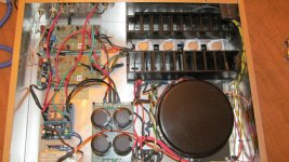
I finally got my scope working. I was interested in checking out near clipping and clipping at specific power.
The rail voltage for this amp is at 62.5 VDC. The bias is set at 75mA. I don't have a distortion analyzer and I don't hear any issues... But?
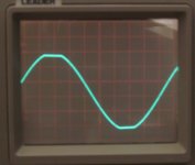
DC off set is 3 and 4 mv. Scope 2V/Div X10 probe.
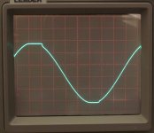
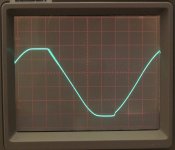
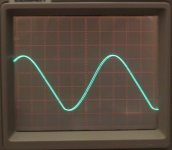
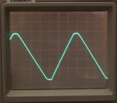
Here as a set of 6 scope traces at various frequencies and measured RMS power under 8 Ohm load.
50 Hz, 1KHz, 5KHz, 10KHz, 15Khz, and 15KHz clip.
50,1k, and 5K clip about 160 Watts. 10kHz about 145 Watts. 15kHz clean to about 100 Watts and get nasty after that. Max power at 15kHz looks like a triangle.
I realize this is not according to the Rod E. plan of construction. I did purchase and use ESP boards. I used double dye mosfet outputs hard wired about 6 inches from the boards.
The rail voltage for this amp is at 62.5 VDC. The bias is set at 75mA. I don't have a distortion analyzer and I don't hear any issues... But?
DC off set is 3 and 4 mv. Scope 2V/Div X10 probe.
Here as a set of 6 scope traces at various frequencies and measured RMS power under 8 Ohm load.
50 Hz, 1KHz, 5KHz, 10KHz, 15Khz, and 15KHz clip.
50,1k, and 5K clip about 160 Watts. 10kHz about 145 Watts. 15kHz clean to about 100 Watts and get nasty after that. Max power at 15kHz looks like a triangle.
I realize this is not according to the Rod E. plan of construction. I did purchase and use ESP boards. I used double dye mosfet outputs hard wired about 6 inches from the boards.
Attachments

Last edited:
Without going into all the design specifics, P101 uses mosfet output devices and will normally dissipate a lot of heat for the power range you expect. Those heatsinks you are using look way too small for the power and you appear to have only a few tiny vent holes in the bottom of the case, unless you are also using some really efficient fans that aren't obvious. Measure the case temperature of those double-die mosfets as you increase power and particularly as the clipping becomes obvious on the 'scope screen. I suggest they'll now be thermal self-limiting, which is what Latfets are good at and make for a bullet-proof output stage. Whilst that means the mosfets should survive, that limiting action still causes clipping distortion and long before they reach their max. power rating.
I also see a stability problem in all that wiring between the PCB and output devices - kinda nullifies any good points about the PCB but you most likely need to get the thermal side right as a priority.
I also see a stability problem in all that wiring between the PCB and output devices - kinda nullifies any good points about the PCB but you most likely need to get the thermal side right as a priority.
Last edited:

Amp dismantled! Boards saved for possible future project with the correct outputs mounted to the pcb's and sinks.
Not sure what to do with the Exicon double die T03 mosfets. I see Exicon is discontinuing call metal T03's.
Too bad! That old Tandberg trans is quite robust giving me 62vdc on the rails. I wish I could find a way to separate the trans from the heat sink ***'y.
Not sure what to do with the Exicon double die T03 mosfets. I see Exicon is discontinuing call metal T03's.
Too bad! That old Tandberg trans is quite robust giving me 62vdc on the rails. I wish I could find a way to separate the trans from the heat sink ***'y.
Take a look at the DH-220C design to get some ideas.Not sure what to do with the Exicon double die T03 mosfets. I see Exicon is discontinuing call metal T03's.
It’s a mechanical design challenge with any custom amp design