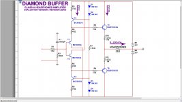
Universal Arm Base that allows 9.5 to 12.5'' tonearm to be fitted to any deck (that I know of, anyway)

Hi, I had written earlier about using an arm base I had developed to show members how they could mount a 10.5 to 12'5'' tonearm on any turntable. I use it on my Lenco plinth.

With this adaptor plate you can mount the arm & align it with any of the 3 standard alignment template, But it also allows the user to try out the Under-Hang alignment with ease.

Advantages of Under-Hang
No anti-skating required (or bent stylus because to much anti skating has been applied)
Easy & much quicker set up. No worrying if the cart stylus is within 0.001mm. +/-0.5mm is quite OK.
No Cartridge Off-Set angle to worry about, you just align your Head-Shell straight. I am quite sure that will a cartridge adaptor you can also use 'S' arms & the like.
BASS did I mention the increase in bass output this new alignment pulls out.
No more buying fancy template to set your arm up, not needed.

Downside
Increased tracking distortion on the LP outer track & less so on the inners. However I cannot hear the effects, but of cause others with golden ears my be able too.

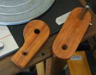
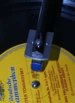
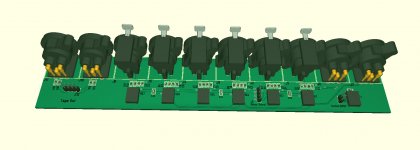
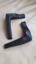
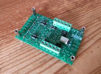
Photo 1 shows you the arm plate in two versions, in fact you could really make it any shape.

The smaller chamfered hole is 8 mm dia with the lager one for my arm at 16 mm dis (this hole need to be made the the diameter to suit your tonearm. The recommended distance between the centres is 72mm.

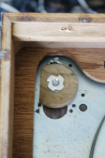
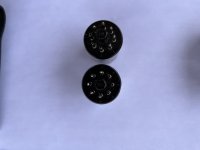
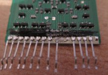
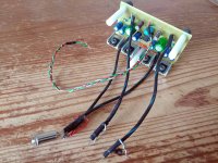
The Arm plate is secured with a M8 counter sunk screw to a retaining plate fitted under your deck. see photo 2

It may be an advantage to make a spacer to fit in the old hole of your T/T plinth the same diameter as already there, with an 8mm dole in the middle.

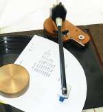
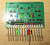
So to align the arm with the manufactured recommended ''spindle to arm length'' all you do is swivel the plate to the left or right. see photo 3 which shows a 9.5'' arm , the next photo a 10.5'' arm all the way up to 12.5''. In Fact you could do longer just by making the base plate longer.

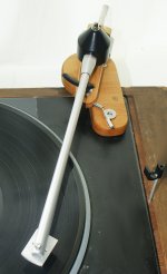
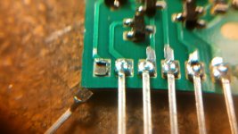
The really good thing in my opinion about using this system is that it allow the user to also easily set their arm to the Under Hang alignment, which I introduced in a previous thread. See photo 5

As said before the neat thing with this way of mounting your arm, apart from going longer. Is that you can also use it for Under Hang alignment. Please don't knock it until you have heard it.

Photo 6 shows how simple it is to do.

Cheers

Attachments

  • Arm Base.jpg
    Arm Base.jpg
    109 KB · Views: 151
  • DSC05209.JPG
    DSC05209.JPG
    240.5 KB · Views: 130
  • DSC05290.JPG
    DSC05290.JPG
    501.7 KB · Views: 131
  • DSC05276.JPG
    DSC05276.JPG
    294.9 KB · Views: 90
  • DSC05293.JPG
    DSC05293.JPG
    652.8 KB · Views: 139
  • DSC05295.JPG
    DSC05295.JPG
    293.7 KB · Views: 125
  • Like
Reactions: sachu888 and adason

It could be an old age thing

I have a very basic pair of 2-way bookshelf speakers (6ohms). The tweeter uses a 1.75mF capacitor as a filter. They sound very flat, lacking in sparkle and brightness. As I cannot believe they sounded this bad out of the box, I surmise the problem must be me, getting old and losing top-end reception. I want to change the capacitors for 2.2mF. Will it make a difference?

100 white vacuum tube boxes, 5 different sizes

sold

Asking $30 to include USA shipping

Here is a lot of unused white vacuum tube boxes I will not use.

(10) 1 x 1 x 2 1/2 inch size, for small 7-pin, short 9 pin type tubes

(52) 1 x 1 x 3 inch size, for typical 12ax7 type tubes

(24) 1 1/4 x 1 1/4 x 3 5/8 inch size, for typical 6sn7 small octal tubes

(8) 1 5/8 x 1 5/8 x 5 inch size, for 6L6GC, thin EL34 type tubes

(10) 1 7/8 x 1 7/8 x 5 3/8 inch size, for 45, 6550 size tubes.

IMG_1935.JPGIMG_1937.JPG

HH SCOTT 340B

HH SCOTT 340B 1963.
Hello. I'm fixing this amp.
the owner claims he bought it working.
as he was fooling around with it he dropped it, broke the 7591 and a cap.
the shock also took out the bridge and the 5 watt 20 ohm on the high voltage side.
now replaced and working as I think he got it.
horrible hum increases as volume is turned up.
also finding lots of AC riding on the DC of the 12ax7.
I really don't want to get to deep into this.
I need some voltage specs on the transformer.
looks like the hum is being introduced to the preamp. possibly all coming from the phono section. looking for some hints.
Thanks

DAVE IACOV

t

Check Soldering Iron grounding?

Hi!
Is this comment in an Amazon review credible, and how would I replicate the test (the leads are not visible in the photo)?
Un-grounded Tip Fried 30% of our Arduinos.
Reviewed in the United States on August 2, 2020
71RaRpTfHoL.jpg

UNGROUNDED TIP WARNING! I rated this 5 stars so it wouldn't get lost in the reviews, but BUYER BEWARE if you are soldering ESD sensitive microelectronics. We had 2 of these in use on our PCB assembly line and after months of mysterious Microcontroller failures we finally traced the issue to this soldering iron. There is 30-volt AC running through the tip, see pic. This fried approx 30% of the Arduino Minis we backpack onto our PCBs. We thought we had a bad batch of mini's but finally found the issue. This soldering iron. Both of our identical units have this issue. Do not buy if you are using on anything remotely electrostatic sensitive.
https://www.amazon.com/Weller-Digital-Soldering-Station-WLC100/dp/B000AS28UC/

gray code volume attenuator

I designed a volume attenuator which only switches one relay at each volume step. Here is a patent describing the circuit, and here is my simulation of a 4bit relay attenuator. It mimics a 20kOhm volume pot: what about the input and output impedance...? The routing is a bit complicated so I went for a 4layer PCB (1st layer is power, 2nd is a GND plane, 3rd and 4th are audio). I didn't build it yet so can't comment on the sound quality. Also I don't know if this was done before... Please let me know what you think!

Attachments

  • schematic.jpg
    schematic.jpg
    75.3 KB · Views: 371
  • pcb.jpg
    pcb.jpg
    247 KB · Views: 367
  • relay.jpg
    relay.jpg
    161.4 KB · Views: 384
  • gerbers.zip
    gerbers.zip
    177.3 KB · Views: 104

For Sale Jensen transformers. 2 JT-11P-1BN

Selling 2 new never been used Jensen JT-11P-1BN for balancing unbalanced inputs. 8 pin octal input. https://www.jensen-transformers.com/wp-content/uploads/2014/08/jt-11p-1bn.pdf
$50.00 each plus $5.00 shipping.

Attachments

  • 313C60AC-92A5-4504-B99C-72A1D2D0783A.jpeg
    313C60AC-92A5-4504-B99C-72A1D2D0783A.jpeg
    246.3 KB · Views: 117
  • 64649685-8187-4579-A2B9-E82754A0E81C.jpeg
    64649685-8187-4579-A2B9-E82754A0E81C.jpeg
    156.8 KB · Views: 116

Fix and Flip Houses

Is this a trend in your area? A bunch of houses in my neighborhood have been subject to this. It's all too common for houses to become quite dilapidated when elderly people live in them. Maintenance is typically deferred for the last ten years or so. (I'm bucking this trend because I'm cleaning and fixing up constantly and won't stop till it's done or I'm dead.) Some of the houses in my area are seriously dilapidated and I wonder about the well being of the occupants.

The adult children are typically so wealthy they can hardly be concerned with a paltry $400,000 house so they do next to nothing and just dump it. The house next door to me is a good example; the resident (he was 99) has been deceased for almost a year and his son has hardly done anything and hasn't even listed it for sale. I do point out stuff wrong and he thanks me but does the bare minimum. Of course I'm wondering about the fate of the house but I think I know what it will be.

I have mixed feelings about fix and flip because I like to see architecture preserved. However, it does restore housing to the market. It makes me wonder what my house is really worth. I intend to sell it when I am offered one million dollars, which could happen the way things are going.

So you can tell when the fix was done. At first everything was grey and white, but the last year it's been black and white. Here's some listings withing a mile of my house. The prices shock me, but I know that people are buying them because they move fast.

https://www.zillow.com/homedetails/7626-Lowell-Ave-Skokie-IL-60076/3546421_zpid/?

https://www.zillow.com/homedetails/4941-Lunt-Ave-Skokie-IL-60077/3554845_zpid/

https://www.zillow.com/homedetails/3906-Cleveland-St-Skokie-IL-60076/3539639_zpid/

https://www.zillow.com/homedetails/8621-Le-Claire-Ave-Skokie-IL-60077/3534433_zpid/

The third house was completely overgrown with weeds and shrubs, and you could smell the mold when you walked past it. Look at it now!


And an obscenely priced "el cheapo" house.

https://www.zillow.com/homedetails/9846-Crawford-Ave-Skokie-IL-60076/3514736_zpid/

What's real estate in your neck of the woods? Zooming into the stratosphere?

STK3042 STK3044 STK3062 STK3082 STK3102 STK3122 STK3152 II III IV V looking for reliable Substitute

Regardless of whether you are dealing with the original versions from Sanyo or with various replicas and various fakes - it just remains unreliable after any replace. An incredible amount of wasted time has already been accomplished (alone in my circle of acquaintances) by this bad design of STK front ends (in order to get low thermal stress).

The reason for this is obvious - simply too weak cooling in the voltage amplifier stage. This means, lokal hot spots and thus premature malfunction. The higher the supply voltage, the greater the power loss and the higher the thermal stress.

I still have a large number of defective amp devices equipped with these STK front end resp. pre-driver modules.
In particular, I would like to get the Sony power amplifier TA-N55ES and the Luxman R5030 so as various Marantz models up and running again permanently.

For a replica I would prefer a 3-transistor LTP (differential amplifier with current source without current mirror) and for the VAS-stage only 2 transistors and 2 heat sinks - one for the gain stage and one for the current source (no SMD resp SMT parts). The loss of sound resulting from this simplification should be negligible.

Maybe someone has done it in this kind.

According to the attached images, the solution in image No and under
https://www.diyaudio.com/community/threads/stk3152-stk3102-clone-for-aluminium-back-pcb.380947/
and post #30 under
https://www.diyaudio.com/community/threads/fake-stk3152-stk3102.268473/page-2
seems to me to be the best.
But it's still not good enough from my view, because one can't mount a BCP56 SMD transistor in the SOT223 outline onto a heat sink (disadvantage is the not good thermal conductivity between PCB and metal/aluminium plate).

Maybe there are even better solutions.

some URL's
http://epicbeardquest.blogspot.com/2016/09/exploring-sanyo-stk3122-iii.html
https://www.diyaudio.com/community/threads/fake-stk3152-stk3102.268473/
https://old-fidelity-forum.de/archive/index.php/thread-41061.html

https://www.diyaudio.com/community/threads/any-modification-for-replacing-stk3102-iv.69472/
https://www.diyaudio.com/community/threads/sanyo-chip-amps-v-ii-xi-differences.170525/
https://www.diyaudio.com/community/threads/i-need-a-information-about-stk3152.4607/
https://www.diyaudio.com/community/threads/connecting-stk-hibryds.187226/
https://www.diyaudio.com/community/threads/amp-crackling-sound.338876/
https://www.diyaudio.com/community/...-amp-module-for-marantz-pm80-amplifier.36425/
https://www.diyaudio.com/community/threads/alternative-for-stk3102-iv.177898/
https://www.diyaudio.com/community/threads/stk3102-iv-manantz-pm-80se-amplifier.55376/
https://www.diyaudio.com/community/threads/stk3062iv-substitute.164588/
https://www.diyaudio.com/community/threads/stk-series-type-amp-bias-adjust-how-is-it-done.26710/
https://www.diyaudio.com/community/threads/marantz-pm-52-no-sound-speakers-or-headphones.309626/

Attachments

  • STK3042.pdf
    STK3042.pdf
    67.1 KB · Views: 265
  • STK3042-II.pdf
    STK3042-II.pdf
    87.9 KB · Views: 224
  • STK3042-III.pdf
    STK3042-III.pdf
    230.7 KB · Views: 400
  • STK3042-STK-3042.jpg
    STK3042-STK-3042.jpg
    76 KB · Views: 543
  • STK3042 old.jpg
    STK3042 old.jpg
    25.7 KB · Views: 467
  • STK 3 0 4 2.jpg
    STK 3 0 4 2.jpg
    182.1 KB · Views: 549
  • Sanyo STK3042.jpg
    Sanyo STK3042.jpg
    106.3 KB · Views: 399
  • Sanyo-STK3042II-image.jpg
    Sanyo-STK3042II-image.jpg
    31 KB · Views: 359
  • stk3042-iii-0919s.jpg
    stk3042-iii-0919s.jpg
    29.9 KB · Views: 526
  • STK3102 replicaII.jpg
    STK3102 replicaII.jpg
    167.4 KB · Views: 655
  • STK3102 repl open.jpg
    STK3102 repl open.jpg
    285.1 KB · Views: 659
  • STK3102 replica.jpg
    STK3102 replica.jpg
    65 KB · Views: 784
  • img00021600x1200_991552.jpg
    img00021600x1200_991552.jpg
    41.8 KB · Views: 595
  • img00011600x1200_991551.jpg
    img00011600x1200_991551.jpg
    168.6 KB · Views: 598
  • STK fake.jpg
    STK fake.jpg
    48.4 KB · Views: 628
  • stk3122-layout.jpg
    stk3122-layout.jpg
    115.4 KB · Views: 768
  • stk3122-orig1.jpg
    stk3122-orig1.jpg
    132.4 KB · Views: 588
  • STK 3122-III fake.jpg
    STK 3122-III fake.jpg
    230.4 KB · Views: 692
  • IMG_20160901_244553_799.jpg
    IMG_20160901_244553_799.jpg
    67.1 KB · Views: 478
  • stk_3102iii-1.jpg
    stk_3102iii-1.jpg
    176.6 KB · Views: 578
  • Like
Reactions: huggygood

Flexible, Battery Power Supply

https://drive.google.com/drive/folders/1o4uLtRahsia_YA-BfH2_vx6bYHdNxxr2

I have made a simple, battery power supply, which, can be used either as a dual ( + - 3.7V ) power supply or a single ( 7.4V ) power supply.

This can be used for anything. Tested and used with Danelectro FAB Metal distortion and overdrive.

The chassis can be connected either to the middle point or to the negative point of the 18650, Li Ion batteries.

The device is simple, just a couple of batteries and a couple of switches, no electronics, nothing else electrical too. However, the device has been found to be very useful.

Indentifying a 6 pin IC

I have an IC- supposedly purchased as a ZXTC2045E6TA-6 pin SMD, but the markings on it show N4 99 t.
I use this IC to repair mobile mono blocks for KICKER. Normally the markings are 2045.

I've looked online and found a code list but cannot find a match between the two.
Can anyone tell me if they are the same part and where I can find a good code list?

MosFET options

Hi.

I am currently rebuilding an Accuphase P - 266 , that came with blown outputs.

Seems the 2sk413 and 2sj118 is well out of production , and the few sources i find is kinda risky.

Is there a substitute that can be used for theese mosfets?
Hopefully something being sold at mouser , digikey or similar

Towards a more reliable digital player.

In a thread I read the suggestion to use an Intel micro-pc instead of using a Raspberry Pi. Since I cannot say that my experience using the Raspberry Pi and IQaudIO DAC is a shiny one, I am creating this thread. The IQaudIO card has nothing to boast about IQ as it sits very closely on the Raspberry Pi with all its digital activity radiating and coupling unwanting signals into it. This results in contaminated output, sometimes even noticeable pauses in music flow. Reading replies in many thread here, suggests that there are far better ways to play music with compared with a Raspberry Pi with a hat sitting on it "happily" eating all sorts of interference and pumping it out through its shiny outputs. Besides of an Intel mini-pc there is also the recommendation to use a USB DAC.

Advice needed - blown Cyrus two

Hi,
Got good answers a couple of years ago on this issue but never followed up unfortunately. Now I decided to finally do something about it.
Bought new fuses, F2 (?) for the PSX. Both needed replacement. But didn't help, still silent and the new ones are OK. At the start up it was this nasty smell again from the PSX. Any further advices what the problem could be? Is it possible to easily stop using the PSX and only use the amplifier itself?

Background:
Have Cyrus Two with PSX, working excellent since 1992 until I managed to shortcut one of the loudspeaker cables (don't ask me how...).
Now it is dead, well both the Cyrus Two and the PSX light up when you turn them on, but no sound at all. I suppose that means the fuses are OK?

There was a light smell so probably some components got damaged. When this occured I haven't started to play so there was no output to the speakers, it occured as soon as I switched power on.

Is also the amplifier damaged, or only the PSX?

Grateful for all advices.

Regards Robert

Question about gain control in consoles

Hi.
I have an AMEK TAC B2 console. The gain on some channels is a little ruff, sometimes I have to turn it all the way up so it will start passing the signal. It's like an obstructed pipe that has to be freed with a massive blow off air.
Does anyone know why?
The console is from around 1984, so it could be a cap. Otherwise it sounds all right, no noise whatsoever.

Thanks in advance for your help.

For Sale Audiotechnology big sale (2): 18H52-SDKA-LR+23I52+10C77 (Troels ATS-4)

UPDATED THREAD
This is the end. Now it is because I have found something that will retire me and I really want to do it.

On the shelf I have lots of high quality and some of the best units for future projects that now won't be build and I have to sell them to make room, money and to get a deffinitive retirement.


For sale:

Audiotechnology Flexunits 10 C 77 25 10 KAP pair SOLD
.

Audiotechnology Cquence 23 I 52 20 06 SD Midwoofer. Mint condition. Measured, tested and stored.
Retail price is 490€ each unit. I'm asking 490€ for the pair.
Original packaging for shipping


Audiotechnology Cquence 18 H 52 06 13 SDKA-LR Midrange. SOLD


Shipping and PP fees is not included.

I can ship WW at cost.

You can PM me your offer if you will combine more items I'm selling. Make a search because there are a lot.
  • Like
Reactions: Arez

TDA7498E Class D Amp (Zk-ht21)

Hey, could someone help with couple questions about this amp.

What’s the Rms of the Subwoofer Channel?
(I don’t really need the speaker channels)

Would it Run my 200watt rms sub?

The idea: I have the (Zk-Tb21) (TPA3116D2) amp am using to power pioneer 30rms 210max speakers so am looking to buy the (Zk-ht21) board and use iPhone Bluetooth to dual connect them and use the (zk-ht21) for the sub ,as if the amp 160watt speaker channels are rms then 2speakers running in series at 8ohm would still be to much at about 60watt so I can’t use the (zk-ht21) for sub and speakers

Building using solid wood

Hi all,

New here, but been reading some of the advice on here for a long while.

I'm a total hobbyist builder, got a few self designed sets around the house and a few friends have asked for them.

It's my dad's birthday next month and I though a nice set of custom speakers for his wee Denon mini system would be nice. Nothing majorly fancy but he does have a livingroom full of white oak furniture.

With that in mind, (and I have read a lot, and I mean a lot, of conflicting views on using solid wood), I though about using 18mm (~3/4") solid oak for the sides, top and bottom, mitred at the corners to try and create a "flow" from panel to panel and look to offset/minimise movement.

For the backs I plan on using oak, cut as an "insert" slightly recessed and screwed to some rails inside sealed with 3M VHB foam tape (I think the black Torx screws would look great). I would use the insulating tape so that I can leave a small gap for movement and still have a sealed enclosure.

For the front, plain old 18mm MDF again as a slightly recessed insert glued in place with the single Dayton Audio RS100-8 and a front firing port cut out and then primed and painted gloss black (to contrast the oak).

Internally, a single 18mm MDF brace under the woofer inside a cabinet that would be 300mm (~12") tall, 150mm (~6") wide and 200mm (~8") deep.

Now, in my head this seems reasonable sensible, they would look good with the "constantly flowing" oak grain as they will be cut from one board and finished with a lovely clear matt Black Bison Wax.

I totally get that I could use an oak veneer but I have had mixed results with veneers and there's something about the weight of solid wood.

Thanks for any or all input all 🙂

Wherever you are, have a great day and thanks for reading.

Cyrus 6 front panel removal and volume repair

Hi all, I have a Cyrus 6 integrated amp with an erratic volume control (rotary encoder) when used manually. Fine with remote. Can anyone advise on how to remove the front panel of the amp so that I can access the encoder to clean it? It looks like the panel just clips onto the chassis. The encoder is visible from the inside of unit and looks fairly small. It is secured by a nut to the panel. It is also soldered to the circuit board at three points. The encoder has four tabs at the back which look to be the access points to disassemble the unit. Have tried squirting a little contact cleaner into the encoder which has fixed to some extent but not entirely. Many thanks for any help. Glenn

Reisong A10/A12 - Replaced tube rectifier to Solid state rectifier ?

Hi,

I bought a Reisong A10 and I convert it on Reisong A12 with following the Stephe's mods (Skunkie Designs).

I plan to replace the tube rectifier to solid state rectifier.

I've a little of 100Hz on the output with 5AR4 tube rectifier from TungSol ...
I want to replace it with solid state rectifier like this (https://www.thomann.de/fr/tad_solid...MIlOmyxLWh_gIVy49oCR2yKgLBEAQYASABEgLzN_D_BwE)

Should I modify the wiring / remove the diodes under the tube socket to swap tube rectifier to solid state rectifier ?

Thank you !
Best regards

Schematic
1681201972375.png

Tube Rectifier Socket
1681202366359.png

Interest in PCBs for Bruno Putzey's Preamp and Hans Polak's relay volume control

In Jan Didden's Linear Audio Vol 5, Bruno Putzeys published an excellent article, called “The G Word, or How to Get Your Audio off the Ground”. The article includes a demo project - a minimalist balanced preamp - and Vol 5 came with a free PCB to make the project a practical build. Then Hans Polak designed an alternative volume controller and a three-way input selector for the preamp. The discussion has been going on here in this thread.

I would like to gauge interest in a group buy for any combination or subset of the following items:
  1. Bare PCB for Bruno Putzey's preamp (BPPBP, a.k.a. MicroPre);
  2. Solder paste stencil for (1), courtesy of Brent from OSH Stencils.
  3. Bare PCB for Hans Polak's 3-way balanced input selector with a pass-through ("Tape") output and a separate output from the preamp.
  4. Bare PCB for Hans Polak's 64-step relay volume controller (I2C control, requires an external MCU, which is not included)
  5. Bare PCB for Hans Polak's 16-step relay volume controller (a simpler alternative to (4), no MCU - it uses a 16-position coded rotary switch to control relays)
Attached are some rendering of the boards.

The pricing would depend on the level of interest, but a blind estimate is $10 for each board (green with HASL finish) and $20 for a polyimide stencil with free shipping to the continental U.S. and $15 shipping elsewhere. If we go for a fancy color (one color for all participants) and ENIG (gold) finish, it may cost a little more.

To put things in perspective, OSHPark - a great service BTW - will charge you $5 per sq inch, or something like $50 for three copies of the BPPBP boards (purple with gold finish), with free shipping worldwide.

Let me know if you are interested.

Update: To give you an idea of the cost of parts for BPPBP, I posted a sample BOM for BPPBP at Mouser.com. It follows the original Linear Audio article and includes Panasonic ERA 0.1% resistors, Nichicon FW and ES electrolytic capacitors, Fujitsu RY relays, 7812 and 7912 regulators instead of HPR12/NHR12 (if you want HxR12, order them at diyclassd.com), PTD902 potentiometer as specified in the original article - although I would replace the pot with one of the relay boards from above or at least with a Vishay Sfernice P9.

Also if needed, I may be able to buy and solder, for a fee, all SMT parts on a few BPPBP boards. A sample SMT-only BOM is here.

Attachments

  • Putz-1.jpg
    Putz-1.jpg
    183.9 KB · Views: 2,162
  • 4 input select_1.jpg
    4 input select_1.jpg
    169.4 KB · Views: 2,089
  • VolCB_1.jpg
    VolCB_1.jpg
    263.2 KB · Views: 2,023
  • 30dB Potentiometer.jpg
    30dB Potentiometer.jpg
    81.3 KB · Views: 2,088

TPA3110 2x15 watt questions from an absolute beginner

I'm trying to make a very small practice amp for bass. At this stage its just the bare minimum to see if I can even do this hobby so tone board isn't in play yet.

Here are my questions about this board: https://s.lazada.co.th/s.8Mmyt

1. The data sheet (from ti, not sure if it applies here) says it can handle 30 watts into a mono load from a 16 volt supply, but it's recommended operating range can go up to 24v. How will going above 16 volts affect the chip?

2. The specifications for this board says 3A max. How do I find the mimum amps this can run on?

My plan was running a variable watt / amp power supply and raising voltage / lowering amperage until the audio sounded better or stopped working but I have no idea what I'm doing.

3. I've heard this chip is quite good at amplifing low signals so would a boost pedal be enough to get my instrument level to line level? not, whats the simplest way to go about this?

I really appreciate anyone who replies. Literally never even held a soldering iron or changed a fuse but got this urge randomly and cant shake it. Sorry if this is answered on the data sheet. Its my first time looking at one and its overwhelming.

Plans like this kick bin?

I've had these nameless kick bins for a while now and they kick pretty dang good having both a front chamber and a back chamber with a port with some kappa 15's in it.

Basically the version I have isn't exactly what I want, shape wise, I'd like them to sit ontop of my subs but its not happening, plus they are old and I'd like to retire & replace them.

So I'm wondering if there is another kick design like this, the main focus wouldn't be max spl but rather lowest ms delay and least muddy sound.

When I say kick bin I mean something from 60-80hz up to say 220-400hz. These lil boxes can go higher and lower than that, but I would like the new ones to be more within that range.

Ideally I'd like a design wider & taller than deep from front to back so that they could be easily stacked ontop of my 18's. Top of each double 18 cab is 27x22 inch and they are designed to be standing so ideally a single 15 would be 27x22 than however tall required to give it enough volume, or a double 15 would be 54x22 than however tall required to give it enough volume.

Something like a martin 215 or a hd15/hd215 are options too, but I'd rather have a cab I can see the driver of personally so I can tell whats going on with it and how hard I'm pushing it.

18mbh65 is another option I've looked at but the problem with it is that it use's a 18 and is pretty big, it wouldn't be good for putting ontop of subs, however I like the design of it.

Ideally I would take whatever design and adapt it to the kappa drivers I can get locally for a reasonable price, so I'm not close minded to coming up with something new or adapting a design to the kappas.

The goal would be front face kick/punch from ontop of the subs.. so maybe even a double 12 design could be a option.

Attachments

  • kick bin.png
    kick bin.png
    56.4 KB · Views: 1,304

EI transformer 160VA 25-0-25 & 0-9V

No markings on the transformer but hand written note with specs taped on.

This is for UK based voltage (240V).

Don't remember where this came from, so not sure if those were the specs listed when I bought it or if I measured at the time in which case likely would be unloaded readings.

160VA 25-0-25 & 0-9V

£10 + postage.

Attachments

  • 16815230325763095709770552095533.jpg
    16815230325763095709770552095533.jpg
    398.5 KB · Views: 72
  • 16815230497331391290967288712334.jpg
    16815230497331391290967288712334.jpg
    341.5 KB · Views: 80

Low Cost High Performance Audio Analyzer

I have been trying to find a high performance low cost analyzer for a while now.
Most are either too expensive, or lack the performance level I like to have. Audio Precision has exactly what I want. But it is way too expensive. There are also a few threads that offer DIY solutions. They lack the performance while being too expensive, they seem to be promoting commercial products. My budget is under $500. I wonder whether I can build the device myself. Clearly, repeating the same designs with the same ICs will get me no where. So, I am thinking to develop my own ADC and DAC. I know it is a difficult task. But everything is impossible until somebody does it. Any advice is much appreciated.

Kitamura Kiden R-Core 40VA 30-0-30V

High quality R- core transformer.

£20 + postage or make an offer.

Product code is 1-433-985'11
K0A1SK

Has hand markings +/-30V & 40VA. I haven't tested this so best to go by product code if you can decipher it.

Can post anywhere, let me know if you're interested and I can get s postage price.

Attachments

  • 16815218632865929276211623035562.jpg
    16815218632865929276211623035562.jpg
    422.1 KB · Views: 232

Best 6DJ8/6AS7 combo

I am currently using a David Yee output transformerless single ended dual triode headphone amp, with an early 70's TOTL Bugle Boy 6DJ8, and an RCA grey-plate 6080. I also have an RCA black-plate 6AS7GA that I found fatiguing in the early stages of using this amp.

The sound of this setup is clean, neutral and balanced. But I am looking for a bigger, more powerful (but controlled) bass, full, natural and lifelike timber and harmonics (like a good DH SET), great soundstage and imaging, and (especially) zero fatigue!

My headphones are the somewhat bass-light, but otherwise completely neutral and transparent JVC HA-D990.

My sources are a Micro Seiki BL51, with a Grace 707 II tonearm, and a Signet TK7e cartridge feeding the world-class phonostage of my Accuphase E-202. A Philips Little Giant DAC + triple filtered LPS being fed by my Carver MV-5 which is serving as a transport.

All of my cables are neutral and transparent hi-end designs (pure copper).

US Satori & SB Audience

Reduced

Selling the following:
1) 1 Pair of SB Audience Rosso-65CDNT (1.41in) $195 ea New / Asking $160 Pair shipped SOLD

2) 1 Pair of SB Audience Rosso-65CD-T (1.4in) $170 New / Asking $140 Pair shipped SOLD

3) 1 Pair of SB Audience H280 horns $48 ea new/ Asking $35 shipped (must be with one pair of the above) SOLD

4) 3 QTY Satori MR16PNW-4 (midrange 4 ohm white cone). $190 ea New / Asking $260 shipped

All drivers are new, never mounted in cabinets. The SB Audience packaging is not mint, but will be well packaged. Satoris come in original packaging. Shipping CONUS only.

Reduced

When it works, it works, or where's my stuff?

I've just received orders from the US sent to the UK. Both arrived in slightly under a week. Honestly, I couldn't believe it, and it got me thinking about all the moving parts that had to be in place for that to happen...

It's a thing that's always had something of a fascination for me ever since James Burkes series Connections. Saw it when I was (a lot) younger and it made me appreciate both the history of science and technology and the complexity of the webs of knowledge and experience that have to be in place for a thing to become an equivalent of an 'overnight' star.

The people, the computer systems, robots, trains, planes, automobiles and more than a couple of thousand years of blood sweat toil and tears combined to get me my stuff.

I really do feel genuinely honoured, lucky, privileged to be around now, to live in a world where such things are possible...

New HF units for Mission M30i

I wasn't quite sure where to put this so if Design & Builds>Parts is more appropriate please Mod me to over there.

My little Mission M30i s have an HF down. I assume the ferro-fliud has dried out but the fabric dome and rubber suspension look worse for wear also. The other one is working but is outwardly as bad as the non-functional one. The XO is visually OK, no dry joints or dodgy looking caps.

They are Vifa units, LOGIC series OC25SC-04 which I believe are long since discontinued. While I have equiries in with Mission and sellers of NOS Vifa units, does anyone on here know a supplier that would probably have them? Ebay and Amazon are no goes as they don't function here.

If in europe I'd probably just buy new speakers but it's rather a HiFi desert here with only the two extremes available i.e. absolute rubbish or high end.

Thanks for your attention.

NAD 317 issue. Power off pop

Hi.
I have a Nad 317 that i changed most of the electrolytic capacitor , since the power board capacitors was way out of spec.
Amplifier works good besides one thing...it makes a pop in left channel when turning off.
I have separated pre amp with poweramp , to find out where the issue starts.
Issue is in the pre amp section , and the pop gets louder with increased volume.

This issue was there before i recapped the amp , and i also double checked tonecontrol board along with volumecontrol board and input board for cracked solderjoints.

Any ideas where i should look next for clues?

Ty

Attachments

  • Polish_20230406_164524625.jpg
    Polish_20230406_164524625.jpg
    228.4 KB · Views: 200
  • Polish_20230406_164329430.jpg
    Polish_20230406_164329430.jpg
    228 KB · Views: 193
  • Polish_20230406_164437900.jpg
    Polish_20230406_164437900.jpg
    83.4 KB · Views: 172
  • Polish_20230406_164404074.jpg
    Polish_20230406_164404074.jpg
    126.2 KB · Views: 219
  • Polish_20230406_164508290.jpg
    Polish_20230406_164508290.jpg
    113.1 KB · Views: 174

search for a replacement for my unfixable Senheiser PX100 II headphones

Hi people,

so my favorite headphones are broken. they were good open and light. Unfortunately they are not produced anymore.
I found them when i was looking for an alternative to coss porta pro but now i am searching again.

Please if you have some lightweight headphones recommendation for a reasonable price tell me.

ps: senheiser px 200 II are not an alternative. they are closed and hard to repair.

Breathable/Mesh Dustcap

Hey folks.

Long time lurker of the great minds here. I purchased some inexpensive PA mids (PRV 10W650A-4) and wanted to fiddle around with a BIB style enclosure. Future plans aside, I just realized that the dust cap is mesh and the speaker has a vented pole piece. From my perspective, that sounds troublesome. I don't necessarily see that being a problem in a vented or BIB enclosure (maybe) but does anyone have experience with a speaker that has these characteristics and what to expect?

My first thought was a phase plug since but I also don't have measuring software and don't feel like paying for the shipping (Guam.)

Any inputs is appreciated.

Two for the price of one

Hey y'all, I purchased two of the ACA kits last year. Version 1.8.

I have completed the build of one but there is a cold solder on the right RCA input. A small wiggle and everything works fine.

The other kit is still in the box but has been opened.

If anybody is in the market for these wonderful sounding amps I am willing to let both of them go for the price of one.$349.00

The goal was to run them in mono configuration but have since moved on to other projects.

If interested, I can send pictures or additional information.

Thanks, David

TDL Studio 3 speaker repair/restoration

Hi all, I recently bought a set of spares or repair TDL Studio 3s. One has no drivers or tweeter. The other has a tweeter (labelled 25DT49 and marked 8ohm) and two 8" drivers (ELAC 8DC471). Note that these are the drivers with six bolts, rather than the four bolt square surround version.

From the Falcon Acoustics ELACIMFTDL spreadsheet (https://www.falconacoustics.co.uk/downloads/Elacimftdl.pdf), it appears that Studio 3s should have 16ohm 8" drivers, so it looks like I've got the drivers from a pair of Studio 2s in there.

I'm not sure all the wiring is original and I believe the crossovers may have been fiddled with. I've struggled to find other pictures of Studio 3 crossovers but these look a fair bit sparser in comparison. I'm no expert (couldn't be farther from it), but from studying the wiring on the pics I could find, I think the one tweeter is wired the wrong way around. Also it looks like the woofers are wired in series (positive from xover to speaker 1, negative from speaker 1 to positive of speaker 2, negative to xover) whereas I think the drivers should be wired in parallel?

Both of the woofer cones appear to be in good condition and move freely, but when I plugged the one speaker with drivers in it into an amp, only 1 of the drivers appears to make a little bit of noise, and I'm not sure the tweeter is working as it ought to be either.

I've done a bit of research and the only similar driver I can find is the Monacor SPH-8M (link: Monacor SPH-8M chassis speaker - Sound Services). I'm assuming I'll need four of these, and won't be able to re-use the 2 x 4 ohm ELAC drivers currently in the cabinets?

Any advice on these Monacors? Will they work? The T/S parameters don't look vastly different, but would appreciate any advice! I'm working on the assumption that I'd wire these 2 x 8 ohm speakers in parallel for a 4 ohm load?

Also, with regards to tweeters, there's not a great deal of info on the originals, but I only have one of them. I've been looking at the Audax 12x9 (link: Audax HD12x9D25 HD12x8D25 spares and replacement voice coils from Falcon Acoustics, The Leading Supplier of DIY Hifi Components.) but not sure if these would be suitable? Firstly, these would be 8ohm. If the 2 x 8ohm woofers would give me a nominal 4 ohm per cab, what impedance tweeter would I want? With the Audaxes above, it doesn't look like the holes on the 12x9 faceplates would be in the right place to attach to the speaker, so am I better off trying to get new tweeter faceplates fabricated and finding a different pair of tweeters to bolt to them?

On top of all this, I'm assuming I'll need to play about with the crossovers to get them working properly with the above speakers.

Any advice, suggestions or recommendations?

Cheers!

Application of Impulse Excitation for DML Design and Analysis

Inspired by tsardoz a few weeks ago, I've been making a lot of use of "tap" testing to identify the natural frequencies of my DML panels. It turns out to be quite informative. By "tap" testing, I mean simply striking the panel and measuring the response using the RTA feature of REW, with the microphone placed very close to the panel. This method is more correctly referred to as impulse excitation. Tsardoz called it "bash" testing! Curiously, I don't think I've ever seen anyone else share tap testing results on this or other forums concerning DMLs.

The most basic use of this technique is (as I mentioned above), simply to identify the natural frequencies of a panel. The frequency response of a DML is highly dependent on its natural frequencies. For example, the panels lowest natural frequency (i.e the fundamental), is approximately the lowest frequency at which can you can expect any significant output. Further, knowledge of the natural frequencies, along with the associated mode shapes (and hence the location of their nodes and antinodes), can help in exciter placement, since it can tell you where to place the exciter in order to excite (or not!) particular modes.

As an example, I will share some tap test results for a 14" by 48" plywood panel I've been working with lately, which was attached to a stiff frame using double sided foam tape around virtually the entire perimeter. In this case the lowest natural frequencies all look like the images below, which show the lowest three modes, that is, the fundamental (or 1,1) and the 1,2 and 1,3 modes, as well as one higher order (1.7) mode.


1645898397454.png 1645898844898.png 1645898938527.png 1645899348606.png

In these images, the red areas are the locations that exhibit the greatest displacement, and are called antinodes. When you tap a panel, the location where you tap determines which modes get excited (i.e. activated), and which do not. If you tap a red (antinode) location for a particular mode, that mode will be excited, while if you tap a blue location (node), that mode will not be excited. So, for example, tapping center of the panel will excite the 1,1 and 1,3 and 1,5 modes etc, since those modes all have an antinode (red) there at the center. On the other hand, tapping the center will not excite the 1,2 (or 1,4 and 1,6 modes etc) since it has a node at the center.
Likewise, the place where you position the microphone determines which modes you will detect. A mic will most easily detect the frequencies which have an antinode at or near the location of the mic.
For these reasons, finding the natural frequencies of a panel usually involves several measurements, made by tapping and mic-ing at a series of different locations.
In the case of my 14x48 panel attached to the frame around the perimeter, only two are needed to get most of the lower frequencies of interest. The first is tapping 2 or 3 inches from one one end of the panel, with the mic the same distance from the opposite end (and within about a 1/2" from the panel face). The other is simply tapping the center of the panel, with the mic also located at the center of the panel.
Here are the RTA measurements for the two tests:
end.jpgcenter.jpg
The first (end tap) shows a series of peaks which each correspond to a natural frequency of the panel. In fact, this captures all (or virtually all) of the natural frequencies of this panel below about 500 Hz, starting with the 1,2 mode at about 85 Hz, up to the 1,9 mode at about 500 Hz. Tapping close to the end, the fundamental was not detected in this first test. However, in the next test (center tap), the fundamental is detected at about 72 Hz. The center tap clearly excites fewer modes (half as many), since it only excites the odd,odd modes (1,1 1,3 1,5 1,7 etc).
Finally, it's interesting to overlay the tap test results with the REW frequency sweep frequency response measured at one meter from the panel. In this case, with a Dayton DAEX25fhe exciter. I placed the exciter about 13 inches from the center in the long direction of the panel, and about 1.375" from the center in the other direction. This was the location that provided the best (flattest) overall frequency response for this particular panel and mounting.
freq.jpg

One thing I found particularly interesting is how the strongest peaks in the overall frequency response correspond exactly to the odd,odd natural frequencies that occur at 72 Hz (1,1), 107 Hz (1,3) and 188 Hz (1,5). And on the other hand, the overall frequency response shows no peaks at the odd,even natural frequencies such as 85 Hz (1,2) and 140 Hz (1,4).
We can learn a lot about how these panels actually work by doing testing of this sort.
Eric

Peerless PMB 100 Head Support Cushions

I have a pair of orthodynamic headphones as in the title. They work fine despite of their age, but the soft foam parts that support on the rear side have deteriorated. They are made of foam, welded in a leather imitation of a special shape. See photo. Is there any chance to replace them? 3D printing perhaps?

Attachments

  • 20230414_122505.jpg
    20230414_122505.jpg
    268.3 KB · Views: 103

Twisted Pear Placid BP Version 2.1.2 revisited

First of all - what are suitable replacements for the defunct Fairchild J1943-O and J5200-O Transistors?
(There were also R-Types that seem to have distributed less power).
Russ was so kind to send me replacements 10 years ago, this weekend I had to use them.
The reason: The precise multi-turn trimmers were/are still too coarse to set the shunted current.
I accidentally turned the wrong ones. About two turns ramped the current up to 400mA which blew one trannie.
As it was R-Types I replaced all four.
And frankly, this board is not for repairs. Desoldering parts
of pushing a leg through a smaller hole makes the traces peel off.

But something must have changed during the swap of the trannies of the Placids.
I have two vintage CD-Players to compare, both running with ordinary 78xx/79xx regulators.
I also use a test CD (Sony YEDS-18) to play "digital silence" so that the relays do not mute.
Anyway, just by playing the silent track an ramping the volume of the amp
all the way up , the results are stunning:
- A vintage Sony CDP-X5000 shows hiss, which might be due to the 1-bit DAC
that has a lot of noise above the audio spectrum.

- A BuffaloII DAC driven by Placids, Single (I think 2.0.1) and BP (2.1.2) - reveals transformer/Mains hum!

- A vintage Philips CD-304MKII, driven with 78xx/79xx voltage regulators - is dead silent!
Even so silent you can hear the swing arm kicking, could be the servo signal bleeding into the audio circuit
or even be mechanical induction.

Interestingly something must have happened - in 2017 I wrote with the same test, the Placids were dead silent
and surpassing the Philips and Sony!

FS drivers Morel - Beyma - Davis - Ciare- RCF

Hi,

Never used or as new:
  • 2* Beyma CP385ND 1p compression driver total 300€
  • 2* Beyma SMC225ND 1p compression driver total 150€
  • 2* RCF ND1411 1p compression driver total 90€

Good condition
2* Morel MW166 (can be used as Dynaudio 17W75 substitution) total 100€
2* DAVIS 13KLV5M 60€
1 CIARE 15.00SW 38 cm bass sub real linear 11mm xmax with good sensitivity 🙂 (Meyer sound used CIARE drivers in their famous subs) 150€

Scan Speak 23W-4557T02 revelator Top compact box sub driver 150€​


I am open to exchange against high quality tweeters ( scanspeak, biesma, sb acoustics, seas, morels AMT ... )
i can add money depending on what...

Pictures on demand
Available in France - Can ship worldwilde

FS [Europe]: UltraBiB and various

Hello,

slowing down the hobby to at least no new project or build. Here is what's left unused from various sources (including trades here!). Make offers and we will estimate shipping then, some parts as the Toslink kit may not be worth sending alone but can be a very cheap added to something else you want.


2x TPA Ventus boards
1x TPA Ivy I/V stage with OPA1632 and X7R supply decoupling caps (no signal filtering caps as it depends on your application)

An ESP project 113 board (from a trade but can't remember much...)


********************************************

Update:
Elma Switches sold,
UltraBiBs sold,
PFM Flea sold,
USB->SPDIF sold,
Toslink input sold,
R-Core TXs sold.
Ventus & IVY sold.
RPi sold.
********************************************

Thanks
Matthieu

Attachments

  • UltraBiB-kits.jpg
    UltraBiB-kits.jpg
    676.1 KB · Views: 515
  • UltraBiB-close-up.jpg
    UltraBiB-close-up.jpg
    500.1 KB · Views: 513
  • XO-PSU-Flea.jpg
    XO-PSU-Flea.jpg
    430.5 KB · Views: 521
  • TPA-Ventus.jpg
    TPA-Ventus.jpg
    581.1 KB · Views: 517
  • IVY-Top.jpg
    IVY-Top.jpg
    518.3 KB · Views: 495
  • IVY-Bottom.jpg
    IVY-Bottom.jpg
    460.5 KB · Views: 187
  • Toslink-Kit.jpg
    Toslink-Kit.jpg
    419.3 KB · Views: 186
  • HeadAmp-ESP-113.jpg
    HeadAmp-ESP-113.jpg
    590.4 KB · Views: 184
  • USBtoSPDIF.jpg
    USBtoSPDIF.jpg
    532 KB · Views: 206

VituixCad Simulations with Ideal Drivers

This is an outgrowth of another thread. It was suggested that we needed a new thread where people could post their VituixCad simulations to enhance the general knowledge of cabinet diffraction issues and baffle layout.

It started with AllenB making a point:
Ironing a driver flat shouldn't be a problem if you choose the passband carefully, however there are many peaks and dips in measurements but many are not due to the drivers. If you EQ them all you may create problems.

I added my thoughts:
To expand on what Allen is saying: It is very enlightening to experiment with VituixCad2 using ideal driver responses, and then simulate a 2-way speaker in a box.

Ideal drivers are the "default" option when you first open VituixCad, the drivers have a perfectly flat response. The next step is to use the diffraction tool and create some baffle shape, and then simulate the horizontal and vertical responses of the ideal tweeter and ideal woofer.

The next step is to build a crossover filter using the active elements available in VituixCad, such as low pass, high pass, notch, shelf, etc. Experimenting with active elements eliminates the complexities of impedance and electrical phase, and it allows us to concentrate on just the acoustical behavior of the simulation.

We might expect that with ideal, perfectly flat drivers, it would be very simple to get a flat response... however, if we simply slapped on a basic LR2, BW3, or LR4 crossover, we would not get a satisfactory result. We will often need quite a bit of filtering to achieve a good response. Baffle step is one obvious area we will have to deal with, but there are other diffraction effects as well. There are also acoustical interactions between the woofer and tweeter depending on their spacing, and on the crossover frequency and slope.

If the goal is a flat on-axis response and a good directivity index behavior, we might need quite a bit of experimenting in VituixCad to get a good simulation. What I found is that there are some baffle shapes/layouts which are easy to work with, and getting a good result is simple... There are other baffle shapes/layouts which are difficult to work with.

If there is an interest, I can post some of the more interesting results I have found... but I don't want to clog up this thread unless there is an interest.

So that is what this thread is about. It would be cool if this thread becomes a repository for interesting simulations...

j.

Note: My first two sims in post #3 and #42 have an error, which is explained in the next dozen or so posts...

A small 3-way is better then a 2-way? Or not? What is your opinion?

for fun i have tried to build a small 3-way, with 1” dome tweeter and 2” dome mid and 6” cone woofer, this far i am not sure it is any better then a straight 2-way using the same dome tweeter and 6” woofer, they sure sound different, by compersion the 2-way sounds edgy and bright and a bit nervous while the 3-way sounds polite and rounded and darker. The 2-way sounds more wild and fun and the 3-way sounds like an old person. Both speakers are built to measure similar both on and off axis.

what is your opinion on such speakers, a 2-way vs a small 3-way?

Cheap (<100€) Digital Tube Tester from ebay; experience/build/mod thread

A few weeks ago I saw this tubetester for the first time on ebay:
DIGITAL TUBE TESTER - LAMPEMETRE AUTONOME ULTRA COMPACT | eBay

I wondered if it would be any good; it seemed to good to be true. I searched if there were people who had any experience with it, but could find nothing. There was some information, but it was all in French; not my strongest language🙄.

I decided to take the chance and order one, and put the experience here on diyaudio. Perhaps some tube lovers will benefit from it.

After I ordered it, I sent an email to the seller; "Rimlok" who had a very good reputation. I asked if he could sent me the manual in english in advance so I could start reading. I got an answer with the manual within 10 minutes, so that went well.

I ordered 20-1 and it arrived 24-1 so that was quick!

In about an hour I had it working and was testing my first tube; see picture.

The tester works really simple; it has two knobs for setting Va (anode/plate voltage) and -Vg (grid (bias) voltage).
If you push the test button it measures the Ia (anode/plate current). It measures pulsed so the tube is safe from overload.

You have to know what you're doing with these kind of testers, because you have to interpret the measurement yourself.
Manuals for vintage tubetesters are easily found on google; you can base setting on these, or use tube-curves to determine a measurement point.
For example: In an old AVO manual I saw that EL34 is mostly tested at Va 250v and -Vg -13.5v. According to the manual 75mA should be "new".

The meter measures in pseudo triode mode. There is an add-on in the manual to build a screen grid supply for true pentode measurements, but I decided to leave that be for now.

I quickly found out that al my old RFT EL34 are in different conditions, but not one broken. To my surprise, I had ordered 4 new electro harmonix el34 in october last year from "elektrodump.nl", 3 of the 4 tubes were defect. This was easy to see on the display, they were pulling grid current (gassy), so the negative Vg drops as the measurement starts. One of them even started flashing in the tube! As you can imagine I was a little bit disappointed... but after telling "elektrodump" my findings, they offered to replace the tubes free of charge! So the tubetester paid itself immediately back!

In the next posts, (if you are interested) the design/build experience, with some caveats here and there...🙂 (and a lot of pictures)

Paul

Attachments

  • IMG-20150124-WA0013.jpeg
    IMG-20150124-WA0013.jpeg
    623.9 KB · Views: 2,095
  • IMG-20150124-WA0015.jpeg
    IMG-20150124-WA0015.jpeg
    556 KB · Views: 2,008
  • IMG-20150125-WA0000.jpeg
    IMG-20150125-WA0000.jpeg
    452.3 KB · Views: 1,965
  • IMG-20150216-WA0005.jpeg
    IMG-20150216-WA0005.jpeg
    470.5 KB · Views: 2,000

Any ebike tinkerers here?

Taking on a new project in an area I know little about. Saw an ad for a fat tire ebike without battery for $200. Figured that was cheap enough that even if it was a mess, should still be worth it. Got it home and took a better look, and it is indeed a mess. Not only is the battery missing, but it's been hacked up pretty good. Everything inside the battery box is loose; in other words it's already a failed project. Looks like someone tried to swap in a non-stock motor controller already (looks like it might not even be for an ebike) with tons of unconnected wires, marrettes (!) and electrical tape. However, I still think I can make a go of it, it's a very simple bike, a Sondors fat tire ebike, just a single speed and a simple handlebar throttle controller, I think I can figure it out. I was hoping someone could point me to web resources that would help me. As in what is a GOOD ebike forum?

Dayton SPA250 hum help

I’ve got a home build subwoofer using a Dayton SPA250 plate amp that I recently pulled out of storage. When I first powered it up I got loud thumping followed by a loud hum with the driver fully extended. (No signal hooked up). I opened it up and found some burnt resistors that I replaced. Now when I plug in I get a hum, very load when the switch is off, but quiets a bit when on. Again no input. If I send an input, it does play. The hum happens in my house and at my office so I think wiring is out. My next thought was the main filter capacitors. She I measure resistance across the caps, on one it starts low and gradually rises but on the other it sits at a constant 2500 ohm ( it’s in parallel with a 3k ohm resistor.) Should that be the next logical part to replace? Any help. Thanks!

Help me choose a DAC on ESS from three options, 🙏

Hello. I ask you to help me decide which of these three dacs is better to buy? As a priority, I would like to focus on the cheaper first option Rod Rain Audio DA68 ES9068AS, but I am confused by how the output circuit is oranized. Why are there only three operational amplifiers?

1. Rod Rain Audio DA68 ES9068AS

https://sl.aliexpress.ru/p?key=4PjSwv0

2. Es9038pro DAC

https://sl.aliexpress.ru/p?key=hCjSwRr

3. ES9038 ES9038PRO DAC 32bit DSD256 DAC Dual R-Core Power transformer

https://sl.aliexpress.ru/p?key=n6jSw9P

ADS L880/2 rebuild

My snowbird neighbors finally showed up with the speakers they picked up for me in Indiana (I bought them off USAudiomart in Nov or early Dec) they just happened to live 30 min up the road but I would have to wait……………until they got here!
Tried them out and they were pretty much what I expected, smooth and clear even at high volume. Two things stuck out, one was an obvious difference in the top end between the two……seeing as these are from the 80’s I pretty much assumed the tweets and mids were gonna need rebuild and am packaging them up to send off to Richard So as he’s the man for ADS! (Actually the only man with parts)
The second thing was a bit more surprising, theres a quite noticeable box resonance in the upper bass / lower mids…..the bracing in the box only amounts to a 2” rib of 3/4” material on each side centered front to back and one piece same size across the front (see pic) I’ve never seen a box braced like this and its fairly obvious why not! So in answer i’ll just put in some cross brace 1” dowel in each direction…….Oh and I reckon there‘s a third thing that kindly surprised me is the orientation of the inductors all on the same plane!?

I’m going to recap the original xo‘s but I also want to build a pair from scratch with better quality components just for the heck of it (please no lectures on the waste of money, snake oil blah blah 😛) after tracing/mapping out the xo’s three times to make sure I got it right I end up with this (see pic) kindly odd can anyone explain that mid configuration? (See pic) tweet is reverse polarity and woofer looks normal.
Does anyone have a schematic for the L880/2 ? I’d like to figure out the inductor values without having to desolder them (unless the DATS V3 can measure accurately in circuit?)

This is the first ferrite core inductor i’ve ever had on a woofer(I take that back, my NS 670’s has them) can saturation come across sounding as a resonance?

edit; forgot to ask should I put a fuse in place of that polyswitch (if so what rating?) or just remove it?

edit II ; upon thinking about removing that polyswitch it dawned on me they do have a resistance even when closed….correct? if so would need a proper value resistor there, right?

Thanks,
MMB

Attachments

  • 816E725E-A091-46E4-BBF9-53D165960CFC.jpeg
    816E725E-A091-46E4-BBF9-53D165960CFC.jpeg
    285.4 KB · Views: 414
  • 6211C945-610A-4667-8637-FD88B002F835.jpeg
    6211C945-610A-4667-8637-FD88B002F835.jpeg
    300.1 KB · Views: 307
  • 44EB01C3-5A4F-4736-80F4-6E4914349D14.png
    44EB01C3-5A4F-4736-80F4-6E4914349D14.png
    5.1 MB · Views: 336

6SN7 with fixed bias

Hello,

I am building an amp with 6SN7 driving interstage transformer as per schematic. I was told that it’s a bad idea to use cathode bypass capacitor on 6SN7 with an IT due to possible resonance. Removing capacitor is not really an option due to resulting impedance.

1680171661448.png


Would a fixed bias be a better option? For example a 6V battery instead of resistor and capacitor, would that work?

Thanks.

Simple Headphones Amplifier on Diamond Buffer based

It's classical schematic from the middle of 1980s. Scheme was took from here AIKIDO - Low-volage with buffer version
I don't know, who invented it, but using tube-preamp with solid state-out topology so strange, I guess... Anyway I decided to assemble this schematic, of cause without tube's preamp, for fun. 🙂
550C+560C may changed on 850C+860C NXP, ON Semi/Fairchild. In output I'm recommending to use MJE15034G+MJE15035G, or MJE243G+MJE253G instead crappy BD139+140 (doesn't matter ON Semi, NXP or NoName, cause their place in Power Supply only). PCB was made with standard "Star" topology and don't has any problems with hum, buzz or another crap.
DC offset doesn't exceed 30 mV (1st channel 1 mV float±2 mV, 2nd channel 25 mV and float ±3 mV). Bias 80 mA±2 mA (1st channel 78 mA, 2nd channel 82 mA and float ±2mA on two channels). One of the channels had problems on 50 kHz square signal caused by "broken" 1N4148. 🙁
The sound likes me a little more, than Lehmann BCL's Diamond Buffer (deeper sound scene, more details on the trebles and a little more aggressive bass).
p/s. It's only test assembling for fun. I like Diamond Buffer's schematics. It's a classic like Group B. I'm not recommending this scheme to amateurs, if you want DB, better start from Lehmann Black Cube Linear schematic or something passed test of time.

Attachments

  • Diamond Buffer Class A HPA.jpg
    Diamond Buffer Class A HPA.jpg
    239.9 KB · Views: 1,289
  • Diamond Buffer Class A HPA v2.jpg
    Diamond Buffer Class A HPA v2.jpg
    239.8 KB · Views: 1,340
  • HPA PS.jpg
    HPA PS.jpg
    287 KB · Views: 1,106
  • DB HPA_SM_002.jpg
    DB HPA_SM_002.jpg
    295.5 KB · Views: 974
  • DB HPA_SM_003.JPG
    DB HPA_SM_003.JPG
    806.1 KB · Views: 852
  • DB HPA_SM_004.JPG
    DB HPA_SM_004.JPG
    827.8 KB · Views: 550
  • DB HPA_SM_006.JPG
    DB HPA_SM_006.JPG
    914.3 KB · Views: 828

Philips 11.289mhz osc needs clock

Here is my long-time Philips friend that needs a nice, clean oscillator circuit. Please help my friend!


The popular, but closed Well Tempered thread is here:
https://www.diyaudio.com/community/...phase-noise-jitter-crystal-oscillator.261651/

I downloaded all of andrea_mori's PDF files but am a bit perplexed as to which particular circuit to use for my Philips, if any.
Maybe another circuit exists that's better suited to the old Philips osc.

Also, what ever happened to Laptech group buys? Can one still purchase them? Or osc's of equal quality from another manuf.?
Maybe the "cut" of the crystal isn't as important at the clcok/osc circuit it is encapsulated by? Yes?

Audio Blue Book 1995 Orion 853 pages

$35.00 OR BEST OFFER

1995 Audio Blue Book, Orion Research Corporation, 853 pages.
Contains very basic info on every piece of audio gear manufactured, Type, Years, WPC, Model Name, New List Price, Retail Used, Wholesale Mint & Ave.
Very little wear, almost as new, see images.
Pioneer takes up 23 pages, Marantz 12 pages.
Sold AS-IS I will be listing more classic audio and radio frequency engineering books, watch my listings.

$6.00 USPS Media Mail shipping to USA
$12.00 Priority/UPS shipping to USA. Will be packed with bubble wrap on all sides to immobilize in box and sufficient to prevent any damage from occuring during shipping.
Shipped promptly, tracking shared, safely packed.

To make purchase message me with your email address and I’ll send you an invoice from PayPal, Venmo or Cash App.

Attachments

  • Orion1.jpg
    Orion1.jpg
    132 KB · Views: 96
  • Orion2.jpg
    Orion2.jpg
    58.3 KB · Views: 97
  • Orion3.jpg
    Orion3.jpg
    72.7 KB · Views: 98
  • Orion4.jpg
    Orion4.jpg
    104.7 KB · Views: 102
  • Orion5.jpg
    Orion5.jpg
    115.4 KB · Views: 100
  • Orion6.jpg
    Orion6.jpg
    128.1 KB · Views: 100
  • Orion7.jpg
    Orion7.jpg
    144.9 KB · Views: 93

E80CC as RH84 driver

Hello, lately I was thinking about building V2 version of RH84 amplifier in closer unspecified future. Since ECC81 is not a cheap tube and I have E80CC in my possesion which has more gain than ECC82 but less than ECC81, I was wondering, if there is a possibility to adjust the schematic, for it to work with that E80CC. Has anyone done it? If not, what do I have to change, or rather how can I calculate the resistor in feedback circuit? Setting the right work point shouldn't be too hard, the only problem is with that feedback resistor.
Thanks

Attachments

  • RH84 - rev2.png
    RH84 - rev2.png
    11.3 KB · Views: 232

OB Full range+ Ported Sub project help

I have just finished designing a speaker that utilizes a p7hd full range driver and dayton sd270A-88 sub. The full range driver is in the open baffle area. I am not experienced with open baffle designs and would like to know if there are any are any glaring issues in that area. I am still working on bracing the exterior of the design so don’t worry about that aspect of the rigidity of this speaker. The blue outline around the front baffle represents a piece of acrylic which I am hoping will reduce the negative effect of edge diffraction. The acrylic sheet will be fused flush with the front baffle. The baffle size is 300mm wide by roughly 1000mm tall. I intend to create a passive crossover between the two and would also appreciate any advice on that end. Generally are there any big issues with this design.

Generally Specs:

Roughly 5 10” in height
Roughly 600mm wide at its widest point
Subwoofer box is separated from the full range driver.
Sub box: 400mm x 400mm x 250mm
Sub port: 3” port 225mm long (tunes to 35hz
Drivers:
Madisound p7hd
https://www.madisoundspeakerstore.c...pluvia-seven-hd-4-metal-cone-full-range-gold/
Dayton 10” sub
https://www.parts-express.com/Dayton-Audio-SD270A-88-10-DVC-Subwoofer-295-486?quantity=1
Designed in Fusion360
C83E2BF8-DE59-4504-A319-9F325E91D092.jpeg
4B90CAA1-9C3F-4D75-96CC-6E029FA30F18.jpeg
439A363F-B53B-43F5-B4DF-BD68CF9A4BEA.jpeg
8DE80D21-5363-4A9F-96F2-712DFDA120B7.jpeg
6B838B2B-E2E7-4B46-A315-B1BA4D777ED4.jpeg
0E41BE74-680E-4BB7-AD8B-855791924F32.jpeg
B3B7E7B3-9BCC-450E-9B73-76E191216C7A.jpeg
  • Like
Reactions: No 4 and gregulator

Help with possible internal standing wave issue

Recently I built some 15" coaxial surrounds (Vortex 15) for my home theater and I'm having an issue with what I believe to be standing waves in the box. The boxes are 48.5x17x12, ported and tuned to about 35Hz.

I ran an impedance sweep on the finished design and this is how it looks with no stuffing.
1681216317793.png


This is approximately what I'd expect. Resonance due to a standing wave of the longest dimension right around 140Hz. So I messed with putting a block of safe n sound insulation in the middle of the box, as well as trying a pillow in the middle of the box, and while they kill the resonance at 140Hz, a resonance shows up at 100Hz. See below.
1681216407241.png


It doesn't look that bad on the impedance sweep, but it is audible. Here's a nearfield sweep in REW. I plugged the port for this to make sure I wasn't getting any port weirdness.
1681216455515.png


I've built other box sizes with these same drivers/crossovers before, and didn't have issues, so I'm ruling out any issues with the drivers or crossovers. I built four of these new boxes and all of them exhibit the same behavior. All of them have drivers and crossovers pulled right out of the old boxes into these new ones.

I'm kind of at a loss of what to try next. I've done testing with the port plugged to make sure the port isn't the issue, and this issue is independent of the port. I've tried adding clamps and boards to the outside of the box to add more bracing to make sure it's not a panel resonance, and I haven't been able to eliminate it that way either. I'm hoping people on this forum will have some suggestions.

My game plan after work is to try putting a pillow right behind the driver, in addition to a pillow halfway down the box, and maybe some loose polyfill in the bottom of the box. But maybe you guys have some other ideas that could help.

Thanks for any and all help.
Projects by fanatics, for fanatics
Get answers and advice for everyone wanting to learn the art of audio.
Join the Community
507,663
Members
7,883,194
Messages

Filter

Forum Statistics

Threads
405,981
Messages
7,883,194
Members
507,663
Latest member
The driver