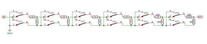
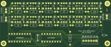
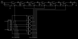
I designed a volume attenuator which only switches one relay at each volume step. Here is a patent describing the circuit, and here is my simulation of a 4bit relay attenuator. It mimics a 20kOhm volume pot: what about the input and output impedance...? The routing is a bit complicated so I went for a 4layer PCB (1st layer is power, 2nd is a GND plane, 3rd and 4th are audio). I didn't build it yet so can't comment on the sound quality. Also I don't know if this was done before... Please let me know what you think!
Attachments
Last edited:

Very nice! Can you do a simulation about input-Z and output-Z? Can you do that with this program?
OK, I did it in the online simulator following this article for the 4bit ladder: input-Z is constant 20k and output-Z is 4k2~10k9 in this order (from soft to loud): 4k2, 7k5, 9k1, 8k8, 9k5, 10k9, 10k6, 8k5, 8k5, 10k6, 10k9, 9k5, 8k9, 9k0, 7k4, 4k2.
Hi jpk73
I’m surprised this is patentable! But maybe tells you more about my lack of understanding about the patent system rather than the circuit.
You seem to have your answer, but you can do this in LTSpice. I really don’t know people don’t seem to know about this feature.
Add a voltage source V1 add a series resistance to the definition and a load resistor RL.
Add the statement
.net I(RL) V1
Run simulation
Go to the plot window and add a trace. Input impedance and output impedance are there as Zin(v1) and Zout(v1).
Sorry could not add screenshots
I think a traditional relay attenuator follows this Zout=Zin*[0 .. 1/2],
a normal pot Zout=Zin*[0 .. 1/4],
a gray code attenuator seems to have Zout=Zin*[0 .. 3/4]
a normal pot Zout=Zin*[0 .. 1/4],
a gray code attenuator seems to have Zout=Zin*[0 .. 3/4]
Last edited:
That patent is expired. Generally an invention can be patented if a technical solution (or manufacturing process) for a given problem is enough different from existing solutions.
I simulated a 6stage Gray attenuator and took measurements to calculate input-Z and output-Z. Result: input-Z stays constant at 20k, output varies somewhere between 8k5 and 15k3, only the two softest and loudest steps drop to a minimum near 4k2, see attached table.
So it seems Zout=Zin*[1/5...3/4] for 6 stages of attenuation.
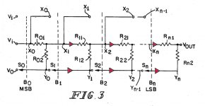
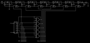
The downside of the Gray code attenuator is that the signal goes through double the number of switching contacts compared to a traditional relay attenuator. Therefor the patent shows another schematic (see attachment): the signal goes through the "normal" number of switches, but the downside is that it needs buffers between the stages. So a 6stage attenuator would consist of 6 relays plus 10 buffers.
To roundup: it seems the Gray code attenuator will sound better during switching because only one relay is switched per step (i.e. less clicks/pops in the signal especially at the 50% transition where in the traditional attenuator the MSB switches). But once the desired volume is reached the traditional attenuator will sound better. Unless you use perfectly transparent buffers of course, or switches without any loss...
I simulated a 6stage Gray attenuator and took measurements to calculate input-Z and output-Z. Result: input-Z stays constant at 20k, output varies somewhere between 8k5 and 15k3, only the two softest and loudest steps drop to a minimum near 4k2, see attached table.
So it seems Zout=Zin*[1/5...3/4] for 6 stages of attenuation.
The downside of the Gray code attenuator is that the signal goes through double the number of switching contacts compared to a traditional relay attenuator. Therefor the patent shows another schematic (see attachment): the signal goes through the "normal" number of switches, but the downside is that it needs buffers between the stages. So a 6stage attenuator would consist of 6 relays plus 10 buffers.
To roundup: it seems the Gray code attenuator will sound better during switching because only one relay is switched per step (i.e. less clicks/pops in the signal especially at the 50% transition where in the traditional attenuator the MSB switches). But once the desired volume is reached the traditional attenuator will sound better. Unless you use perfectly transparent buffers of course, or switches without any loss...
Attachments
Last edited:
Would a 2 Form D relay solve this problem?
That’s a DPDT make-before-break relay.
I was actually looking for one of these earlier in the weeks - seems they only exist on paper - sadly.
That’s a DPDT make-before-break relay.
I was actually looking for one of these earlier in the weeks - seems they only exist on paper - sadly.
It must be examined whether the Gray code is of any use in practice. You don't turn a volume knob by one step, but by 10 or 20 steps, if I have a 127-step range. And in these cases you have to switch all the relays again. The Gray code can only show its advantage in 1-step processes.
For example:
000000<-from here e.g.
000001
000011
000010
000110
000111<-to here
000101
000100
001100
...
For example:
000000<-from here e.g.
000001
000011
000010
000110
000111<-to here
000101
000100
001100
...
Last edited:
Here is the simulation of the buffered Gray attenuator following the schematic from #9. I again simulated to replace a 20k pot using 6 stages. All resistors are 10k. As a result I got a constant input-Z of 20K and a constant output-Z of 5K.
So it has Zout=Zin/4
Not bad - but so many buffers! Any ideas??
(Attached the simulation layouts)
So it has Zout=Zin/4
Not bad - but so many buffers! Any ideas??
(Attached the simulation layouts)
Attachments
MMB will only address the issue that the relay contact is floating during flying from one state to the other: there is a short period of time without any connection...Would a 2 Form D relay solve this problem?
That’s a DPDT make-before-break relay.
I was actually looking for one of these earlier in the weeks - seems they only exist on paper - sadly.
But surely with make before break the second connection is made before the last is broken? There is never a time without connection in my understanding. Maybe you can break it down for me (terrible pun).
Relays bounce, is this what you mean? But surely a well designed relay 2 Form D will take that settling time into account.
Relays bounce, is this what you mean? But surely a well designed relay 2 Form D will take that settling time into account.
16 steps is awfully course.
I did a volume circuit with cd4066 that was 10 bit. That produces a seamless range of 80db.
I did a volume circuit with cd4066 that was 10 bit. That produces a seamless range of 80db.
- Home
- Source & Line
- Analog Line Level
- gray code volume attenuator